
R21xx-HP FlexFabric 11900 High Availability Configuration Guide

83
Configuring BFD for the VRRP master to monitor the uplinks
Network requirements
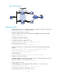
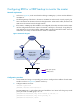
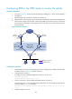
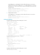
• As shown in Figure 23, Switch A and Switch B belong to VRRP group 1, whose virtual IP address is
192.168.0.10.
• The default gateway of the hosts in the LAN is 192.168.0.10.
• When Switch A works properly, the hosts in the LAN access the external network through Switch A.
When Switch A detects that the uplink is down through BFD, it decreases its priority so that Switch
B can preempt as the master, ensuring that the hosts in the LAN can access the external network
through Switch B.
Figure 23 Network diagram
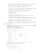
Configuration procedure
1. Create VLANs and assign corresponding ports to them. Configure the IP address of each VLAN
interface as shown in Figure 23. (Details not shown.)
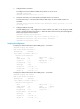
2. Configure BFD on Switch A:
# Configure the source address of BFD echo packets as 10.10.10.10.
<SwitchA> system-view
[SwitchA] bfd echo-source-ip 10.10.10.10
3. Create a track entry to be associated with the BFD session on Switch A:
# Create track entry 1 to be associated with the BFD session to check whether the uplink device
with the IP address 1.1.1.2 is reachable.
[SwitchA] track 1 bfd echo interface vlan-interface 3 remote ip 1.1.1.2 local ip
1.1.1.1
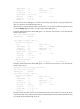
4. Configure VRRP on Switch A:
Internet
Master
uplink device
Backup
uplink device
Uplink
Virtual router
Virtual IP address:
192.168.0.10
Vlan-int2
192.168.0.101/24
Vlan-int2
192.168.0.102/24
Switch A
Master
Switch B
Backup
Vlan-int3
1.1.1.1/24
Vlan-int3
1.1.1.2/24
L2 switch
Uplink
VRRP packets
BFD probe packets