
R21xx-HP FlexFabric 11900 High Availability Configuration Guide

87
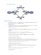
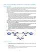
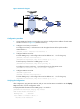
Figure 24 Network diagram
Configuration procedure
1. Create VLANs and assign corresponding ports to them. Configure the IP address of each VLAN
interface as shown in Figure 24. (Details not shown.)
2. Configure Switch A:
# Configure a static route to 30.1.1.0/24, with the address of the next hop as 10.1.1.2 and the
default priority 60. This static route is associated with track entry 1.
<SwitchA> system-view
[SwitchA] ip route-static 30.1.1.0 24 10.1.1.2 track 1
# Configure a static route to 30.1.1.0/24, with the address of the next hop as 10.3.1.3 and the
priority 80.
[SwitchA] ip route-static 30.1.1.0 24 10.3.1.3 preference 80
# Configure a static route to 10.2.1.4, with the address of the next hop as 10.1.1.2.
[SwitchA] ip route-static 10.2.1.4 24 10.1.1.2
# Create an NQA test group with the administrator admin and the operation tag test.
[SwitchA] nqa entry admin test
# Configure the test type as ICMP-echo.
[SwitchA-nqa-admin-test] type icmp-echo
# Configure the destination address of the test as 10.2.1.4 and the next hop address as 10.1.1.2
to check the connectivity of the path from Switch A to Switch B and then to Switch D through NQA.
[SwitchA-nqa-admin-test-icmp-echo] destination ip 10.2.1.4
[SwitchA-nqa-admin-test-icmp-echo] next-hop 10.1.1.2
# Configure the test frequency as 100 ms.
[SwitchA-nqa-admin-test-icmp-echo] frequency 100
# Configure reaction entry 1, specifying that five consecutive probe failures trigger the Track
module.
[SwitchA-nqa-admin-test-icmp-echo] reaction 1 checked-element probe-fail
threshold-type consecutive 5 action-type trigger-only
[SwitchA-nqa-admin-test-icmp-echo] quit
# Start the NQA test.