HP FlexFabric 11900 Switch Series IP Multicast Configuration Guide Part number: 5998-4062 Software version: Release 2105 and later Document version: 6W100-20130515
Legal and notice information © Copyright 2013 Hewlett-Packard Development Company, L.P. No part of this documentation may be reproduced or transmitted in any form or by any means without prior written consent of Hewlett-Packard Development Company, L.P. The information contained herein is subject to change without notice.
Contents Multicast overview ······················································································································································· 1 Introduction to multicast ···················································································································································· 1 Information transmission techniques ·····················································································································
Configuring multicast routing and forwarding ········································································································· 33 Overview········································································································································································· 33 RPF check mechanism ··········································································································································· 33 Static multica
Configuring PIM ························································································································································· 64 Overview········································································································································································· 64 PIM-DM overview ··············································································································································
How MLD snooping works ································································································································· 107 Protocols and standards ····································································································································· 109 MLD snooping configuration task list ························································································································· 109 Configuring basic MLD snooping
Configuring MLD ····················································································································································· 136 Overview······································································································································································· 136 How MLDv1 works ·············································································································································· 136
Configuration task list ········································································································································· 168 Configuration prerequisites ································································································································ 168 Configuring an IPv6 multicast data filter··········································································································· 169 Configuring a hello message filt
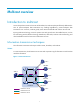
Multicast overview Introduction to multicast As a technique that coexists with unicast and broadcast, the multicast technique effectively addresses the issue of point-to-multipoint data transmission. By enabling high-efficiency point-to-multipoint data transmission over a network, multicast greatly saves network bandwidth and reduces network load.
In Figure 1, assume that Host B, Host D and Host E need the information. A separate transmission channel must be established from the information source to each of these hosts. In unicast transmission, the traffic transmitted over the network is proportional to the number of hosts that need the information. If a large number of hosts need the information, the information source must send a separate copy of the same information to each of these hosts.
Figure 3 Multicast transmission The multicast source sends only one copy of the information to a multicast group. Host B, Host D, and Host E, which are information receivers, must join the multicast group. The routers on the network duplicate and forward the information based on the distribution of the group members. Finally, the information is correctly delivered to Host B, Host D, and Host E.
• Routers or Layer 3 switches that support Layer 3 multicast are called "multicast routers" or "Layer 3 multicast devices." In addition to providing the multicast routing function, a multicast router can also manage multicast group memberships on stub subnets with attached group members. A multicast router itself can be a multicast group member. For a better understanding of the multicast concept, you can compare multicast transmission to the transmission of TV programs.
Multicast applications • Multimedia and streaming applications, such as web TV, web radio, and real-time video/audio conferencing • Communication for training and cooperative operations, such as distance learning and telemedicine • Data warehouse and financial applications (stock quotes) • Any other point-to-multipoint application for data distribution Multicast models Based on how the receivers treat the multicast sources, the multicast models include any-source multicast (ASM), source-filtered mul
• Where is the multicast source that will provide data to the receivers? (Multicast source discovery.) • How should information be transmitted to the receivers? (Multicast routing.) IP multicast is an end-to-end service. The multicast architecture involves the following parts: • Addressing mechanism—A multicast source sends information to a group of receivers through a multicast address. • Host registration—Receiver hosts can join and leave multicast groups dynamically.
Table 3 Some reserved multicast addresses • Address Description 224.0.0.1 All systems on this subnet, including hosts and routers. 224.0.0.2 All multicast routers on this subnet. 224.0.0.3 Unassigned. 224.0.0.4 DVMRP routers. 224.0.0.5 OSPF routers. 224.0.0.6 OSPF designated routers and backup designated routers. 224.0.0.7 Shared Tree (ST) routers. 224.0.0.8 ST hosts. 224.0.0.9 RIPv2 routers. 224.0.0.11 Mobile agents. 224.0.0.12 DHCP server/relay agent. 224.0.0.
Table 4 Flags field description Bit Description 0 Reserved, set to 0. • When set to 0, it indicates that this address is an IPv6 multicast address without an embedded RP address. • When set to 1, it indicates that this address is an IPv6 multicast R address with an embedded RP address. (The P and T bits must also be set to 1.) • When set to 0, it indicates that this address is an IPv6 multicast address not based on a unicast prefix.
Figure 6 IPv4-to-MAC address mapping The most significant four bits of a multicast IPv4 address are 1110. Only 23 bits of the remaining 28 bits are mapped to a MAC address, so five bits of the multicast IPv4 address are lost. As a result, 32 multicast IPv4 addresses map to the same IPv4 multicast MAC address. Therefore, a device might receive some unwanted multicast data at Layer 2 processing, which needs to be filtered by the upper layer.
{ Layer 3 multicast refers to IP multicast working at the network layer. Layer 3 multicast protocols—IGMP, MLD, PIM, IPv6 PIM, MSDP, MBGP, and IPv6 MBGP. { Layer 2 multicast refers to IP multicast working at the data link layer. Layer 2 multicast protocols—IGMP snooping, MLD snooping, PIM snooping, IPv6 PIM snooping, multicast VLAN, and IPv6 multicast VLAN. • IPv4 and IPv6 multicast protocols: { For IPv4 networks—IGMP snooping, PIM snooping, multicast VLAN, IGMP, PIM, MSDP, and MBGP.
A multicast routing protocol runs on Layer 3 multicast devices to establish and maintain multicast routes and correctly and efficiently forward multicast packets. Multicast routes constitute loop-free data transmission paths (also known as multicast distribution trees) from a data source to multiple receivers. In the ASM model, multicast routes include intra-domain routes and inter-domain routes.
• PIM snooping and IPv6 PIM snooping: PIM snooping and IPv6 PIM snooping run on Layer 2 devices. They determine which ports are interested in multicast data by analyzing the received IPv6 PIM messages, and add the ports to a multicast forwarding entry to make sure multicast data can be forwarded to only the ports that are interested in the data.
Configuring IGMP snooping Overview IGMP snooping runs on a Layer 2 switch as a multicast constraining mechanism to improve multicast forwarding efficiency. It creates Layer 2 multicast forwarding entries from IGMP packets that are exchanged between the hosts and the router. As shown in Figure 10, when IGMP snooping is not enabled, the Layer 2 switch floods multicast packets to all devices.
Figure 11 IGMP snooping related ports The following describes the ports involved in IGMP snooping: • Router port—Layer 3 multicast device-side port. Layer 3 multicast devices include designated routers (DRs) and IGMP queriers. In Figure 11, Ten-GigabitEthernet 1/0/1 of Switch A and Ten-GigabitEthernet 1/0/1 of Switch B are the router ports. A switch records all its router ports in the router port list.
Timer Description Dynamic member port aging timer. When a port dynamically joins a multicast group, the switch starts an aging timer for the port. When the timer expires, the dynamic member port ages out. Message received before the timer expires Action after the timer expires IGMP membership report. The switch removes the port from the IGMP snooping forwarding table. NOTE: In IGMP snooping, only dynamic ports age out. Static ports never age out.
• If a forwarding entry matches the group address and the receiving port is in the forwarding entry for the group, the switch restarts the aging timer for the port. In an application with a group filter configured on an IGMP snooping-enabled switch, when a user requests a multicast program, the user's host initiates an IGMP report. After receiving this report, the switch resolves the multicast group address in the report and looks up the ACL.
If the port receives no IGMP report in response to the group-specific query before its aging timer • expires, it indicates that no hosts attached to the port are still listening to that group address. The switch removes the port from the forwarding entry for the multicast group after the aging timer for the port expires.
Enabling IGMP snooping When you enable IGMP snooping, follow these guidelines: • You must enable IGMP snooping globally before you enable it for a VLAN. • IGMP snooping for a VLAN takes effect only on the ports in that VLAN. To enable IGMP snooping: Step Command Remarks 1. Enter system view. system-view N/A 2. Enable IGMP snooping globally and enter IGMP-snooping view. igmp-snooping By default, IGMP snooping is disabled. 3. Return to system view. quit N/A 4. Enter VLAN view.
Setting the maximum number of IGMP snooping forwarding entries You can modify the maximum number of IGMP snooping forwarding entries. When the number of forwarding entries on the device reaches the upper limit, the device does not automatically remove any existing entries or create new entries until some entries time out or are removed. In this case, HP recommends that you manually remove the excessive entries. To set the maximum number of IGMP snooping forwarding entries: Step Command Remarks 1.
Step Set the IGMP last-member query interval. 4. Command Remarks last-member-query-interval interval The default setting is 1 second. Configuring parameters for IGMP queries and responses in a VLAN Step Command Remarks 1. Enter system view. system-view N/A 2. Enter VLAN view. vlan vlan-id N/A 3. Set the maximum response time for IGMP general queries in the VLAN. igmp-snooping max-response-time interval The default setting is 10 seconds. Set the IGMP last-member query interval.
Step Command Remarks 2. Enter IGMP-snooping view. igmp-snooping N/A 3. Set the aging timer for dynamic router ports globally. router-aging-time interval The default setting is 260 seconds. 4. Set the global aging timer for dynamic member ports globally. host-aging-time interval The default setting is 260 seconds. Setting the aging timers for the dynamic ports in a VLAN Step Command Remarks 1. Enter system view. system-view N/A 2. Enter VLAN view. vlan vlan-id N/A 3.
Step Configure the port as a static router port. 4. Command Remarks igmp-snooping static-router-port vlan vlan-id By default, a port is not a static router port. Enabling IGMP snooping fast-leave processing The IGMP snooping fast-leave processing feature enables the switch to process IGMP leave messages quickly.
Configuring IGMP snooping policies Before you configure IGMP snooping policies, complete the following tasks: • Enable IGMP snooping for the VLAN. • Determine the ACL used as the multicast group filter. • Determine the maximum number of multicast groups that a port can join. Configuring a multicast group filter When you configure a multicast group filter, follow these guidelines: This configuration is effective for the multicast groups that a port dynamically joins.
When dropping unknown multicast data is disabled, the switch floods unknown multicast data in • the VLAN to which the unknown multicast data belongs, causing network bandwidth waste and low forwarding efficiency. When dropping unknown multicast data is enabled, the switch forwards unknown multicast data to • its router ports instead of flooding it in the VLAN. If no router ports exist, the switch drops the unknown multicast data.
If the multicast group replacement is disabled, the switch or the port discards IGMP reports that are • used for joining a new multicast group. In some specific applications, such as channel switching, a newly joined multicast group must automatically replace an existing multicast group. In this case, the function of multicast group replacement must also be enabled so a user can switch from the current multicast group to a new group.
Task Command Display information about dynamic IGMP snooping forwarding entries (in IRF mode). display igmp-snooping group [ group-address | source-address ] * [ vlan vlan-id ] [ verbose ] [ chassis chassis-number slot slot-number ] Display information about static IGMP snooping forwarding entries (in standalone mode).
IGMP snooping configuration examples Group policy configuration example Network requirements As shown in Figure 12, Router A runs IGMPv2 and serves as the IGMP querier, and Switch A runs IGMPv2 snooping. To enable Host A and Host B to receive only the multicast data addressed to the multicast group 224.1.1.1, configure IGMP snooping on Switch A and enable the switch to drop unknown multicast data instead of flooding it in VLAN 100. Figure 12 Network diagram Receiver Host A Source XGE1/0/2 1.1.1.2/24 1.1.
3. Configure Switch A: # Enable IGMP snooping globally. system-view [SwitchA] igmp-snooping [SwitchA-igmp-snooping] quit # Create VLAN 100, assign Ten-GigabitEthernet 1/0/1 through Ten-GigabitEthernet 1/0/4 to the VLAN, and enable IGMP snooping and the function of dropping unknown multicast data for the VLAN.
Static port configuration example Network requirements As shown in Figure 13, Router A runs IGMPv2 and serves as the IGMP querier, and Switch A, Switch B, and Switch C run IGMPv2 snooping. Host A and host C are permanent receivers of multicast group 224.1.1.1. Configure Ten-GigabitEthernet 1/0/3 and Ten-GigabitEthernet 1/0/5 on Switch C as static member ports for multicast group 224.1.1.1 to enhance the reliability of multicast traffic transmission. Suppose the STP runs on the network.
Configuration procedure 1. Assign an IP address and subnet mask to each interface as shown in Figure 13. (Details not shown.) 2. On Router A, enable IP multicast routing globally, enable IGMP on Ten-GigabitEthernet 1/0/1, and enable PIM-DM on each interface.
[SwitchC] igmp-snooping [SwitchC-igmp-snooping] quit # Create VLAN 100, assign Ten-GigabitEthernet 1/0/1 through Ten-GigabitEthernet 1/0/5 to the VLAN, and enable IGMP snooping for the VLAN. [SwitchC] vlan 100 [SwitchC-vlan100] port ten-gigabitethernet 1/0/1 to ten-gigabitethernet 1/0/5 [SwitchC-vlan100] igmp-snooping enable [SwitchC-vlan100] quit # Configure Ten-GigabitEthernet 1/0/3 and Ten-GigabitEthernet 1/0/5 as static member ports for multicast group 224.1.1.1.
Troubleshooting IGMP snooping Layer 2 multicast forwarding cannot function Symptom Layer 2 multicast forwarding cannot function on the switch. Analysis IGMP snooping is not enabled. Solution 1. Use the display igmp-snooping command to display IGMP snooping status. 2. If IGMP snooping is not enabled, use the igmp-snooping command in system view to enable IGMP snooping globally, and then use the igmp-snooping enable command in VLAN view to enable IGMP snooping for the VLAN. 3.
Configuring multicast routing and forwarding Overview The following tables are involved in multicast routing and forwarding: • Multicast routing table of each multicast routing protocol, such as the PIM routing table. • General multicast routing table that summarizes multicast routing information of different multicast routing protocols. The multicast routing information from multicast sources to multicast groups are stored in a set of (S, G) routing entries.
{ The router looks up its static multicast routing table by using the IP address of the packet source as the source address, and automatically chooses an optimal static multicast route. The route explicitly defines the RPF interface and the RPF neighbor. 2. The router selects one of the two optimal routes as the RPF route according to the following principles: { If the router uses the longest prefix match principle, the router selects the matching route as the RPF route.
• If a forwarding entry matches the packet but the interface that received the packet is not the incoming interface of the forwarding entry, the multicast packet undergoes an RPF check. { If the RPF interface is the incoming interface, it indicates that the forwarding entry is correct, but the packet traveled along a wrong path. The router discards the packet.
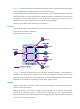
Changing an RPF route Typically, the topology structure of a multicast network is the same as that of a unicast network, and multicast traffic follows the same transmission path as unicast traffic does. You can configure a static multicast route for a given multicast source to change the RPF route, so that the router creates a transmission path for multicast traffic that is different from the transmission path for unicast traffic.
Figure 16 Creating an RPF route Multicast Routing Table Static on Switch C Source/Mask Interface RPF neighbor/Mask OSPF domain 192.168.0.0/24 Vlan-int10 1.1.1.1/24 Switch D Receiver Multicast Routing Table Static on Switch D Source/Mask Interface RPF neighbor/Mask 192.168.0.0/24 Vlan-int20 2.2.2.2/24 Source Vlan-int20 2.2.2.1/24 RIP domain Vlan-int10 1.1.1.1/24 192.168.0.1/24 Switch A Multicast packets Vlan-int10 1.1.1.2/24 Switch B Vlan-int20 2.2.2.
Figure 17 Multicast data transmission through a tunnel As shown in Figure 17, with a tunnel established between the multicast routers Switch A and Switch B, Switch A encapsulates the multicast data in unicast IP packets, and forwards them to Switch B across the tunnel through unicast routers. Then, Switch B strips off the unicast IP header and continues to forward the multicast data to the receiver.
Step Command Remarks 1. Enter system view. system-view N/A 2. Enable IP multicast routing. multicast routing-enable By default, IP multicast routing is disabled. Configuring multicast routing and forwarding Before you configure multicast routing and forwarding, complete the following tasks: Configure a unicast routing protocol so that all devices in the domain are interoperable at the • network layer. Enable PIM-DM or PIM-SM.
Step 2. Configure the device to select the RPF route based on the longest prefix match. Command Remarks multicast longest-match By default, the route with the highest priority is selected as the RPF route. Configuring multicast load splitting To optimize the traffic delivery for multiple data flows, you can configure load sharing on a per-source basis or on a per-source-and-group basis. To configure multicast load splitting: Step Command Remarks 1. Enter system view. system-view N/A 2.
You can configure static multicast MAC address entries on the specified interface in system view, or • on the current interface in interface view. The multicast MAC address that can be manually configured in the multicast MAC address entry • must be unused. (The least significant bit of the most significant octet is 1.) To configure a static multicast MAC address entry in system view: Step Command Remarks 1. Enter system view. system-view N/A 2. Configure a static multicast MAC address entry.
Task Command Display multicast forwarding table information (in IRF mode). display multicast forwarding-table [ source-address [ mask { mask-length | mask } ] | group-address [ mask { mask-length | mask } ] | chassis chassis-number slot slot-number | incoming-interface interface-type interface-number | outgoing-interface { exclude | include | match } interface-type interface-number | statistics ] * Display information about the multicast routing table.
Figure 18 Network diagram Switch C Vlan-int103 40.1.1.1/24 PIM-DM Vlan-int103 40.1.1.2/24 Switch A Vlan-int200 50.1.1.1/24 Vlan-int101 20.1.1.2/24 Vlan-int101 20.1.1.1/24 Vlan-int102 30.1.1.2/24 Vlan-int102 30.1.1.1/24 Source Switch B Vlan-int100 10.1.1.1/24 Receiver 50.1.1.100/24 10.1.1.100/24 Multicast static route Configuration procedure 1. Configure the IP address and subnet mask for each interface as shown in Figure 18. (Details not shown.) 2.
[SwitchA] interface vlan-interface 200 [SwitchA-Vlan-interface200] pim dm [SwitchA-Vlan-interface200] quit [SwitchA] interface vlan-interface 102 [SwitchA-Vlan-interface102] pim dm [SwitchA-Vlan-interface102] quit [SwitchA] interface vlan-interface 103 [SwitchA-Vlan-interface103] pim dm [SwitchA-Vlan-interface103] quit # Enable IP multicast routing and PIM-DM on Switch C in the same way. (Details not shown.) # Use the display multicast rpf-info command to display the RPF route to the source on Switch B.
Creating an RPF route Network requirements PIM-DM runs in the network and all switches in the network support IP multicast. Switch B and Switch C run OSPF, and have no unicast routes to Switch A. Typically, the receiver host receives the multicast data from the source 1 in the OSPF domain. Perform the configuration so that the receiver host receives multicast data from the source 2, which is outside the OSPF domain. Figure 19 Network diagram Configuration procedure 1.
[SwitchC-Vlan-interface101] quit # On Switch A, enable IP multicast routing globally and enable PIM-DM on each interface. system-view [SwitchA] multicast routing-enable [SwitchA] interface vlan-interface 300 [SwitchA-Vlan-interface300] pim dm [SwitchA-Vlan-interface300] quit [SwitchA] interface vlan-interface 102 [SwitchA-Vlan-interface102] pim dm [SwitchA-Vlan-interface102] quit # Enable IP multicast routing and PIM-DM on Switch B in the same way. (Details not shown.
Multicast forwarding over a GRE tunnel Network requirements Multicast routing and PIM-DM are enabled on Switch A and Switch C. Switch B does not support multicast. OSPF is running on Switch A, Switch B, and Switch C. Perform the configuration so that the receiver host can receive the multicast data from the source. Figure 20 Network diagram Configuration procedure 1. Configure the IP address and subnet mask for each interface as shown in Figure 20. (Details not shown.) 2.
[SwitchA-Tunnel0] ip address 50.1.1.1 24 [SwitchA-Tunnel0] source 20.1.1.1 [SwitchA-Tunnel0] destination 30.1.1.2 [SwitchA-Tunnel0] quit # Create service loopback group 1 on Switch C and specify its service type as Tunnel. system-view [SwitchC] service-loopback group 1 type tunnel # Disable STP and LLDP on interface Ten-GigabitEthernet 1/0/3 of Switch C, and add the interface to service loopback group 1. Ten-GigabitEthernet 1/0/3 does not belong to VLAN 200 or VLAN 102.
[SwitchC-Vlan-interface102] quit [SwitchC] interface tunnel 0 [SwitchC-Tunnel0] pim dm [SwitchC-Tunnel0] quit 5. On Switch C, configure a static multicast route, specifying the RPF neighbor toward the source as interface Tunnel 0 on Switch A. [SwitchC] ip rpf-route-static 50.1.1.0 24 50.1.1.1 Verifying the configuration The source sends the multicast data to the multicast group 225.1.1.1 and the receiver host can receive the multicast data after joining the multicast group.
Troubleshooting multicast routing and forwarding Static multicast route failure Symptom No dynamic routing protocol is enabled on the routers, and the physical status and link layer status of interfaces are both up, but the static multicast route fails. Analysis • If a static multicast route is not correctly configured or updated to match the current network conditions, it does not exist in the static multicast routing table. • If a better route is found, the static multicast route might also fail. 1.
Configuring IGMP Overview Internet Group Management Protocol (IGMP) establishes and maintains the multicast group memberships between a Layer 3 multicast device and its directly connected hosts. IGMP has three versions: • IGMPv1 (defined by RFC 1112) • IGMPv2 (defined by RFC 2236) • IGMPv3 (defined by RFC 3376) All IGMP versions support the ASM model. In addition to the ASM model, IGMPv3 can directly implement the SSM model.
Figure 21 IGMP queries and reports IP network DR Router A Router B Ethernet Host A (G2) Host B (G1) Host C (G1) Query Report As shown in Figure 21, Host B and Host C are interested in the multicast data addressed to the multicast group G1, and Host A is interested in the multicast data addressed to G2. The following process describes how the hosts join the multicast groups and how the IGMP querier (Router B in Figure 21) maintains the multicast group memberships: 1.
IGMPv1 does not define a leave group message (often called a "leave message"). When an IGMPv1 host is leaving a multicast group, it stops sending reports to that multicast group. If the subnet has no members for a multicast group, the IGMP routers will not receive any report addressed to that multicast group. In this case, the routers clear the information for that multicast group after a period of time.
local subnet has no member hosts for the group and stops maintaining the memberships for the group. IGMPv3 enhancements IGMPv3 is based on and is compatible with IGMPv1 and IGMPv2. It provides hosts with enhanced control capabilities and provides enhancements of query and report messages. Enhancements in control capability of hosts IGMPv3 introduced two source filtering modes (Include and Exclude).
Enhancements in query and report capabilities • Query message carrying the source addresses IGMPv3 is compatible with IGMPv1 and IGMPv2 and supports general queries and group-specific queries. It also introduces group-and-source-specific queries. • { A general query does not carry a group address or a source address. { A group-specific query carries a group address, but no source address. { A group-and-source-specific query carries a group address and one or more source addresses.
IGMP configuration task list Task at a glance Configuring basic IGMP functions • • • • (Required.) Enabling IGMP (Optional.) Specifying the IGMP version (Optional.) Configuring an interface as a static member interface (Optional.) Configuring a multicast group filter Adjusting IGMP performance (Optional.
To specify an IGMP version: Step Command Remarks 1. Enter system view. system-view N/A 2. Enter interface view. interface interface-type interface-number N/A 3. Specify an IGMP version. igmp version version-number IGMPv2 by default.
Step Command Remarks 1. Enter system view. system-view N/A 2. Enter interface view. interface interface-type interface-number N/A 3. Configure a multicast group filter. igmp group-policy acl-number [ version-number ] By default, no multicast group filter is configured on any interface. Hosts attached to an interface can join any multicast group.
Displaying and maintaining IGMP CAUTION: The reset igmp group command might cause multicast data transmission failures. Execute display commands in any view and reset command in user view. Task Command Display IGMP group information. display igmp group [ group-address | interface interface-type interface-number ] [ static | verbose ] Display IGMP information.
Figure 23 Network diagram Receiver PIM network Host A 01 -int1 Vlan Switch A Querier Vlan -in t201 Vlan-int100 10.110.1.1/24 N1 Host B Vlan-int200 10.110.2.1/24 Receiver Host C Switch B Vlan-int200 10.110.2.2/24 Vlan -int2 02 N2 Host D Switch C Configuration procedure 1. Assign the IP address and subnet mask to each interface as shown in Figure 23. (Details not shown.) 2.
[SwitchB-Vlan-interface200] igmp enable [SwitchB-Vlan-interface200] pim dm [SwitchB-Vlan-interface200] quit [SwitchB] interface vlan-interface 201 [SwitchB-Vlan-interface201] pim dm [SwitchB-Vlan-interface201] quit # On Switch C, enable IP multicast routing globally, enable IGMP on VLAN-interface 200, and enable PIM-DM on each interface.
Troubleshooting IGMP No membership information on the receiver-side router Symptom When a host sends a report for joining the multicast group G, no membership information of the multicast group G exists on the router closest to that host. Analysis • The correctness of networking and interface connections and whether the protocol layer of the interface is up directly affect the generation of group membership information. • Multicast routing must be enabled on the router.
Analysis • A router running IGMP maintains multiple parameters for each interface. Inconsistent IGMP interface parameter configurations for routers on the same subnet will result in inconsistency of memberships. • In addition, although IGMP routers are partially compatible with hosts that separately run different versions of IGMP, all routers on the same subnet must run the same version of IGMP. Inconsistent IGMP versions running on routers on the same subnet leads to inconsistency of IGMP memberships.
Configuring PIM Overview Protocol Independent Multicast (PIM) provides IP multicast forwarding by leveraging unicast static routes or unicast routing tables generated by a unicast routing protocol, such as RIP, OSPF, IS-IS, or BGP. PIM is not dependent on any particular unicast routing protocol, and it uses the underlying unicast routing to generate a routing table with routes. PIM uses the RPF mechanism to implement multicast forwarding.
In PIM-DM, the multicast forwarding paths for a multicast group constitutes a source tree, which is rooted at the multicast source and has multicast group members as its "leaves." Because the source tree consists of the shortest paths from the multicast source to the receivers, it is also called a "shortest path tree (SPT).
Figure 24 SPT building Host A Source Receiver Host B Server Receiver SPT Prune message Multicast packets Host C The pruned state of a branch has a finite holdtime timer. When the timer expires, multicast data is again forwarded to the pruned branch. The flood-and-prune cycle takes place periodically to maintain the forwarding branches.
Figure 25 Assert mechanism As shown in Figure 25, after Router A and Router B receive an (S, G) packet from the upstream node, they both forward the packet to the local subnet. As a result, the downstream node Router C receives two identical multicast packets, and both Router A and Router B, on their own downstream interfaces, receive a duplicate packet forwarded by the other. After detecting this condition, both routers send an assert message to all PIM routers (224.0.0.
• When a receiver expresses it interest in the multicast data addressed to a specific multicast group, the receiver-side designated router (DR) sends a join message to the RP for the multicast group. The path along which the message goes hop by hop to the RP forms a branch of the RPT. • When a multicast source sends multicast data to a multicast group, the source-side DR must register the multicast source with the RP by unicasting register messages to the RP.
Figure 26 DR election As shown in Figure 26, the DR election process is as follows: 1. The routers on the shared-media LAN send hello messages to one another. The hello messages contain the priority for DR election. The router with the highest DR priority is elected as the DR. 2. In the case of a tie in the priority, or if any router in the network does not support carrying the DR-election priority in hello messages, the router with the highest IP address wins the DR election.
BSR encapsulates the RP-set information in the bootstrap messages (BSMs) and floods the BSMs to the entire PIM-SM domain. Figure 27 Information exchange between C-RPs and BSR Based on the information in the RP-set, all routers in the network can select the proper RP for a specific multicast group based on the following rules: 1. The C-RP that is designated to the smallest multicast group range wins. 2. In the case of a tie in the multicast group range, the C-RP with the highest priority wins. 3.
RPT building Figure 28 RPT building in a PIM-SM domain Host A Source RP DR Server Receiver Host B DR Receiver RPT Join message Multicast packets Host C As shown in Figure 28, the process of building an RPT is as follows: 1. When a receiver wants to join the multicast group G, it uses an IGMP message to inform the receiver-side DR. 2. After getting the receiver information, the DR sends a join message, which is forwarded hop by hop to the RP that provides services for the multicast group. 3.
Figure 29 Multicast source registration As shown in Figure 29, the multicast source registers with the RP as follows: 1. The multicast source S sends the first multicast packet to the multicast group G. When receiving the multicast packet, the source-side DR encapsulates the packet in a PIM register message and unicasts the message to the RP. 2. After the RP receives the register message, it decapsulates the register message and forwards the register message down to the RPT.
• Encapsulation and decapsulation are complex on the source-side DR and the RP. • The path for a multicast packet might not be the shortest one. • The RP might be overloaded by multicast traffic bursts. To eliminate these weaknesses, PIM-SM allows an RP or the receiver-side DR to initiate a switchover to SPT. • The RP initiates a switchover to SPT: When the RP receives the first (S, G) multicast packet, it sends an (S, G) source-specific join message hop by hop toward the multicast source.
Administrative scoping mechanism The administrative scoping mechanism effectively releases stress on the management in a single-BSR domain and enables provision of zone-specific services through private group addresses. Admin-scoped zones are divided for multicast groups. Zone border routers (ZBRs) form the boundary of an admin-scoped zone. Each admin-scoped zone maintains one BSR for multicast groups within a specific range.
multiple admin-scope zones. Different admin-scope zones contain different routers. However, the global-scoped zone includes all routers in the PIM-SM domain. Multicast packets that do not belong to any admin-scope zones are forwarded in the entire PIM-SM domain. • In view of multicast group address ranges: Each admin-scope zone provides services for specific multicast groups, of which the multicast group addresses are valid only within the local zone.
Task at a glance (Optional.) Configuring PIM-DM graft retry timer (Optional.) Configuring common PIM features Configuration prerequisites Before you configure PIM-DM, configure a unicast routing protocol so that all devices in the domain are interoperable at the network layer Enabling PIM-DM Enable IP multicast routing before you configure PIM. With PIM-DM enabled on interfaces, routers can establish PIM neighbor relationship and process PIM messages from their PIM neighbors.
Step Command Remarks 2. Enter interface view. interface interface-type interface-number N/A 3. Enable the state refresh feature. pim state-refresh-capable By default, the state refresh feature is enabled. Configuring state refresh parameters The router directly connected with the multicast source periodically sends state refresh messages. You can configure the interval for sending such messages on that router. A router might receive duplicate state refresh messages within a short time.
To configure the graft retry timer: Step Command Remarks 1. Enter system view. system-view N/A 2. Enter interface view. interface interface-type interface-number N/A 3. Configure the graft retry timer. pim timer graft-retry interval By default, the graft retry timer is 3 seconds. Configuring PIM-SM PIM-SM configuration task list Task at a glance (Required.) Enabling PIM-SM (Required.
IMPORTANT: All the interfaces on the same router must operate in the same PIM mode. To enable PIM-SM: Step Command Remarks 1. Enter system view. system-view N/A 2. Enable IP multicast routing. multicast routing-enable By default, IP multicast routing is disabled. 3. Enter interface view. interface interface-type interface-number N/A 4. Enable PIM-SM. pim sm By default, PIM-SM is disabled. Configuring an RP An RP can provide services for multiple multicast groups.
auto-RP announcements from other routers. Then, it organizes the C-RP information into the RP-set information, which is flooded throughout the entire network. Then, the other routers in the network can determine the RPs for different multicast group ranges based on the RP-set information. HP recommends configuring C-RPs on backbone routers. To enable the BSR to distribute the RP-set information in the PIM-SM domain, the C-RPs must periodically send advertisement messages to the BSR.
When a C-BSR receives the BSM from another C-BSR, it compares its own priority with the priority • carried in the message. The C-BSR with a higher priority wins the BSR election. If a tie exists in the priority, the C-BSR with a higher IP address wins. The loser uses the winner's BSR address to replace its own BSR address and no longer regards itself as the BSR, and the winner retains its own BSR address and continues to regard itself as the BSR.
Step (Optional.) Configure a legal BSR address range. 4. Command Remarks bsr-policy acl-number By default, no restrictions are defined. Configuring a PIM domain border As the administrative core of a PIM-SM domain, the BSR sends the collected RP-set information in the form of bootstrap messages to all routers in the PIM-SM domain. A PIM domain border is a bootstrap message boundary. Each BSR has its specific service scope.
Step Command Remarks 2. Enter PIM view. pim N/A 3. Disable the BSM semantic fragmentation function. undo bsm-fragment enable By default, BSM semantic fragmentation is enabled. NOTE: Generally, a BSR performs BSM semantic fragmentation according to the MTU of its BSR interface. However, for BSMs originated due to learning of a new PIM neighbor, semantic fragmentation is performed according to the MTU of the interface that sends the BSMs.
Step Command Remarks 1. Enter system view. system-view N/A 2. Enter PIM view. pim N/A 3. Configure the criteria for triggering a switchover to SPT. spt-switch-threshold { immediacy | infinity } [ group-policy acl-number ] By default, both the receiver-side DR and the RP immediately trigger a switchover to SPT after receiving the first multicast packet. Configuring common PIM features Configuration task list Task at a glance (Optional.) Configuring a multicast data filter (Optional.
Step Command Remarks 1. Enter system view. system-view N/A 2. Enter PIM view. pim N/A 3. Configure a multicast data filter: source-policy acl-number By default, no multicast data filter is configured. Configuring a hello message filter Along with the wide applications of PIM, the security requirement for the protocol is becoming increasingly demanding. The establishment of correct PIM neighboring relationships is the prerequisite for secure application of PIM.
a prune message. If the prune message delay or override interval on different PIM routers on a shared-media LAN are different, the largest value takes effect. A router does not immediately prune an interface after it receives a prune message from the interface. Instead, it starts a timer (the prune message delay plus the override interval). If interface receives a join message before the override interval expires, the router does not prune the interface.
Configuring hello message options on an interface Step Command Remarks 1. Enter system view. system-view N/A 2. Enter interface view. interface interface-type interface-number N/A 3. Set the DR priority. pim hello-option dr-priority priority By default, the DR priority is 1. 4. Set the neighbor lifetime. pim hello-option holdtime time By default, the neighbor lifetime is 105 seconds. 5. Set the prune delay.
Configuring common PIM timers globally Step Command Remarks 1. Enter system view. system-view N/A 2. Enter PIM view. pim N/A 3. Set the interval to send hello messages. timer hello interval By default, the interval to send hello messages is 30 seconds. 4. Set the interval to send join/prune messages. timer join-prune interval By default, the interval to send join/prune messages is 60 seconds. 5. Set the joined/pruned state holdtime timer.
Step 3. Set the maximum size of each join or prune message. Command Remarks jp-pkt-size size By default, the maximum size of a join or prune message is 8100 bytes. Enabling PIM to work with BFD PIM uses hello messages to elect a DR for a shared-media network. The elected DR is the only multicast forwarder on the shared-media network. If the DR fails, a new DR election process will start after the DR is aged out.
Task Command Display PIM routing table information. display pim routing-table [ group-address [ mask { mask-length | mask } ] | source-address [ mask { mask-length | mask } ] | flags flag-value | fsm | incoming-interface interface-type interface-number | mode mode-type | outgoing-interface { exclude | include | match } interface-type interface-number ] * Display RP information in the PIM-SM domain.
Switch B Switch C VLAN-interface 200 10.110.2.1/24 VLAN-interface 101 192.168.2.2/24 VLAN-interface 101 192.168.2.1/24 VLAN-interface 102 192.168.3.2/24 VLAN-interface 200 10.110.2.2/24 VLAN-interface 102 192.168.3.1/24 Configuration procedure 1. Configure the IP address and subnet mask for each interface as per Figure 32. (Details not shown.) 2.
Vlan103 1 30 1 192.168.1.2 (local) Vlan101 1 30 1 192.168.2.2 (local) Vlan102 1 30 1 192.168.3.2 (local) # Display PIM neighboring relationships on Switch D. [SwitchD] display pim neighbor Total Number of Neighbors = 3 Neighbor Interface Uptime 192.168.1.1 Vlan103 00:02:22 00:01:27 1 Expires Dr-Priority 192.168.2.1 Vlan101 00:00:22 00:01:29 3 192.168.3.1 Vlan102 00:00:23 00:01:31 5 Assume that Host A needs to receive the information addressed to multicast group 225.1.1.1.
(10.110.5.100, 225.1.1.
Figure 33 Network diagram Receiver Host A Switch A Vlan-int102 Host B Vl an -in t1 01 Vl an -in t1 01 Vlan-int100 Vlan-int300 Vlan-int102 Vlan-int105 Vlan-int105 Source Switch D Vlan-int103 Switch E 10.110.5.100/24 Receiver Vlan-int200 Vlan-int103 Vlan-int104 Switch B Host C Vlan-int104 Vlan-int200 PIM-SM Host D Switch C Device Interface IP address Device Interface IP address Switch A Vlan-int100 10.110.1.1/24 Switch D Vlan-int300 10.110.5.1/24 Vlan-int101 192.168.1.
[SwitchA-Vlan-interface100] pim sm [SwitchA-Vlan-interface100] quit [SwitchA] interface vlan-interface 101 [SwitchA-Vlan-interface101] pim sm [SwitchA-Vlan-interface101] quit [SwitchA] interface vlan-interface 102 [SwitchA-Vlan-interface102] pim sm [SwitchA-Vlan-interface102] quit # Enable IP multicast routing, IGMP, and PIM-SM on Switch B and Switch C in the same way. (Details not shown.) # Enable IP multicast routing and PIM-SM on Switch D and Switch E in the same way. (Details not shown.) 4.
Bootstrap timer: 00:01:44 Elected BSR address: 192.168.9.2 Priority: 20 Hash mask length: 32 Uptime: 00:40:40 # Display BSR information on Switch D. [SwitchD] display pim bsr-info Scope: non-scoped State: Candidate Bootstrap timer: 00:01:44 Elected BSR address: 192.168.9.2 Priority: 20 Hash mask length: 32 Uptime: 00:05:26 Candidate BSR address: 192.168.4.2 Priority: 10 Hash mask length: 32 # Display BSR information on Switch E.
The source 1 and the source 2 send different multicast data to the multicast group 239.1.1.1. Host A receives the multicast data only from the source 1, and Host B receives the multicast data only from the source 2. The source 3 sends multicast data to the multicast group 224.1.1.1. Host C is a multicast receiver for the multicast group 224.1.1.1.
Switch H Switch I Vlan-int103 10.110.2.2/24 Vlan-int106 10.110.6.1/24 Vlan-int110 10.110.10.1/24 Vlan-int106 10.110.6.2/24 Vlan-int600 192.168.6.1/24 Vlan-int110 10.110.10.2/24 Switch G Vlan-int500 192.168.5.1/24 Vlan-int109 10.110.9.2/24 Source 1 - 192.168.2.10/24 Source 2 - 192.168.3.10/24 Source 3 - 192.168.5.10/24 Configuration procedure 1. Assign an IP address and subnet mask to each interface according to Figure 34. (Details not shown.) 2.
4. Configure admin-scoped zone boundaries: # On Switch B, configure VLAN-interface 102 and VLAN-interface 103 as the boundaries of admin-scoped zone 1. [SwitchB] interface vlan-interface 102 [SwitchB-Vlan-interface102] multicast boundary 239.0.0.0 8 [SwitchB-Vlan-interface102] quit [SwitchB] interface vlan-interface 103 [SwitchB-Vlan-interface103] multicast boundary 239.0.0.
[SwitchF-pim] c-bsr 10.110.9.1 [SwitchF-pim] c-rp 10.110.9.1 [SwitchF-pim] quit Verifying the configuration # Display BSR information on Switch B. [SwitchB] display pim bsr-info Scope: non-scoped State: Accept Preferred Bootstrap timer: 00:01:44 Elected BSR address: 10.110.9.1 Priority: 64 Hash mask length: 30 Uptime: 00:01:45 Scope: 239.0.0.0/8 State: Elected Bootstrap timer: 00:00:06 Elected BSR address: 10.110.1.2 Priority: 64 Hash mask length: 30 Uptime: 00:04:54 Candidate BSR address: 10.110.1.
Scope: non-scoped State: Elected Bootstrap timer: 00:00:49 Elected BSR address: 10.110.9.1 Priority: 64 Hash mask length: 30 Uptime: 00:11:11 Candidate BSR address: 10.110.9.1 Priority: 64 Hash mask length: 30 # Display RP information on Switch B. [SwitchB] display pim rp-info BSR RP information: Scope: non-scoped Group/MaskLen: 224.0.0.0/4 RP address Priority HoldTime Uptime Expires 10.110.9.1 192 150 00:03:39 00:01:51 RP address Priority HoldTime Uptime Expires 10.110.1.
Troubleshooting PIM A multicast distribution tree cannot be correctly built Symptom A multicast distribution tree cannot be correctly built because there are no multicast forwarding entries established on the routers (including routers directly connected with multicast sources or receivers) in a PIM network. Analysis • On a PIM-DM enabled network, multicast data is flooded from the router that directly connects to the multicast source to the routers that directly connects to the receivers.
4. Verify that PIM and IGMP are enabled on the interfaces that directly connect to the multicast sources or the receivers. 5. Use display pim interface verbose to verify that the same PIM mode is enabled on the RPF interface on a router and the connected interface of the router's RPF neighbor. 6. Use display current-configuration to verify that the same PIM mode is enabled on all routers. For PIM-SM, verify that the BSR and C-RPs are correctly configured.
Solution 1. Use display ip routing-table to verify that a unicast route to the RP is available on each router. 2. Use display pim rp-info to verify that the dynamic RP information is consistent on all routers. 3. Use display pim rp-info to verify that the same static RPs are configured on all routers on the network. An RPT cannot be built or multicast source registration fails in PIM-SM Symptom The C-RPs cannot unicast advertisement messages to the BSR.
Configuring MLD snooping Overview MLD snooping runs on a Layer 2 switch as an IPv6 multicast constraining mechanism to improve IPv6 multicast forwarding efficiency. It creates Layer 2 IPv6 multicast forwarding entries from MLD packets that are exchanged between the hosts and the router. As shown in Figure 35, when MLD snooping is not enabled, the Layer 2 switch floods IPv6 multicast packets to all devices.
Figure 36 MLD snooping related ports The following describes the ports involved in MLD snooping, as shown in Figure 36: • Router port—Layer 3 multicast device-side port. Layer 3 multicast devices include designated routers and MLD queriers. In Figure 36, Ten-GigabitEthernet 1/0/1 of Switch A and Switch B are the router ports. A switch records all its local router ports in the router port list.
Timer Description Dynamic member port aging timer. When a port dynamically joins a multicast group, the switch starts an aging timer for the port. When the timer expires, the dynamic member port ages out. Message received before the timer expires Action after the timer expires MLD report message. The switch removes the port from the MLD snooping forwarding table. NOTE: In MLD snooping, only dynamic ports age out. Static ports never age out.
• If a forwarding entry matches the group address, but the receiving port is not in the forwarding entry for the group, the switch adds the port as a dynamic member port to the forwarding entry, and starts an aging timer for the port. • If a forwarding entry matches the group address and the receiving port is in the forwarding entry for the group, the switch restarts the aging timer for the port.
multicast group address. The switch removes the port from the forwarding entry for the IPv6 multicast group after the aging timer for the port expires. Protocols and standards RFC 4541, Considerations for Internet Group Management Protocol (IGMP) and Multicast Listener Discovery (MLD) Snooping Switches MLD snooping configuration task list Task at a glance Configuring basic MLD snooping functions • • • • (Required.) Enabling MLD snooping (Optional.) Specifying the MLD snooping version (Optional.
Enabling MLD snooping When you enable MLD snooping, follow these guidelines: • You must enable MLD snooping globally before you enable it for a VLAN. • MLD snooping for a VLAN works only on the ports in that VLAN. To enable MLD snooping: Step Command Remarks 1. Enter system view. system-view N/A 2. Enable MLD snooping globally and enter MLD-snooping view. mld-snooping By default, MLD snooping is disabled. 3. Return to system view. quit N/A 4. Enter VLAN view. vlan vlan-id N/A 5.
Setting the maximum number of MLD snooping forwarding entries You can modify the maximum number of MLD snooping forwarding entries. When the number of forwarding entries on the device reaches the upper limit, the device does not automatically remove any existing entries or create new entries until some entries time out or are removed. In this case, HP recommends that you manually remove excessive entries. To set the maximum number of MLD snooping forwarding entries: Step Command Remarks 1.
Step Set the MLD last-listener query interval. 4. Command Remarks last-listener-query-interval interval The default setting is 1 second. Configuring parameters for MLD queries and responses in a VLAN Step Command Remarks 1. Enter system view. system-view N/A 2. Enter VLAN view. vlan vlan-id N/A 3. Set the maximum response delay for MLD general queries in the VLAN. mld-snooping max-response-time interval The default setting is 10 seconds.
Step Command Remarks 2. Enter MLD-snooping view. mld-snooping N/A 3. Set the aging timer for dynamic router ports globally. router-aging-time interval The default setting is 260 seconds. 4. Set the aging timer for dynamic member ports globally. host-aging-time interval The default setting is 260 seconds. Setting the aging timers for the dynamic ports in a VLAN Step Command Remarks 1. Enter system view. system-view N/A 2. Enter VLAN view. vlan vlan-id N/A 3.
Step Command Remarks 3. Configure the port as a static member port. mld-snooping static-group ipv6-group-address [ source-ip ipv6-source-address ] vlan vlan-id By default, a port is not a static member port. 4. Configure the port as a static router port. mld-snooping static-router-port vlan vlan-id By default, a port is not a static router port. Enabling MLD snooping fast-leave processing The MLD snooping fast-leave processing feature enables the switch to process MLD done messages quickly.
Configuring MLD snooping policies Before you configure MLD snooping policies, complete the following tasks: • Enable MLD snooping for the VLAN. • Determine the ACL used as the IPv6 multicast group filter. • Determine the maximum number of IPv6 multicast groups that a port can join. Configuring an IPv6 multicast group filter When you configure an IPv6 multicast group filter, follow these guidelines: This configuration is effective for the IPv6 multicast groups that the port dynamically joins.
Enabling dropping unknown IPv6 multicast data Unknown IPv6 multicast data refers to IPv6 multicast data for which no forwarding entries exist in the MLD snooping forwarding table. When the switch receives such multicast data, one of the following occurs: When the function of dropping unknown IPv6 multicast data is disabled, the switch floods unknown • IPv6 multicast data in the VLAN to which the unknown IPv6 multicast data belongs.
Enabling the IPv6 multicast group replacement function When the number of IPv6 multicast groups on a switch or a port exceeds the limit: If the IPv6 multicast group replacement is enabled, the switch or the port replaces an existing IPv6 • multicast group with a newly joined IPv6 multicast group. If the IPv6 multicast group replacement is disabled, the switch or the port discards MLD reports for • joining a new IPv6 multicast group.
Task Command Display MLD snooping status. display mld-snooping [ global | vlan vlan-id ] Display information about dynamic MLD snooping forwarding entries (in standalone mode). display mld-snooping group [ ipv6-group-address | ipv6-source-address ] * [ vlan vlan-id ] [ verbose ] [ slot slot-number ] Display information about dynamic MLD snooping forwarding entries (in IRF mode).
MLD snooping configuration examples IPv6 group policy configuration example Network requirements As shown in Figure 37, Router A runs MLDv1 and serves as the MLD querier, and Switch A runs MLDv1 snooping. To enable Host A and Host B to receive only the IPv6 multicast data addressed to the IPv6 multicast group FF1E::101, configure MLD snooping on Switch A and enable the switch to drop unknown IPv6 multicast data instead of flooding it in VLAN 100.
3. Configure Switch A: # Enable MLD snooping globally. system-view [SwitchA] mld-snooping [SwitchA-mld-snooping] quit # Create VLAN 100, assign Ten-GigabitEthernet 1/0/1 through Ten-GigabitEthernet 1/0/4 to the VLAN, and enable MLD snooping and the function of dropping IPv6 unknown multicast data for the VLAN.
Static port configuration example Network requirements As shown in Figure 38, Router A runs MLDv1 and serves as the MLD querier, and Switch A, Switch B, and Switch C run MLDv1 snooping. Host A and Host C are permanent receivers of the IPv6 multicast group FF1E::101. Configure Ten-GigabitEthernet 1/0/3 and Ten-GigabitEthernet 1/0/5 on Switch C as static member ports for the IPv6 multicast group FF1E::101 to enhance the reliability of IPv6 multicast traffic transmission. Suppose the STP runs on the network.
Configuration procedure 1. Assign an IPv6 address and prefix length to each interface according to Figure 38. (Details not shown.) 2. On Router A, enable IPv6 multicast routing, enable MLD on Ten-GigabitEthernet 1/0/1, and enable IPv6 PIM-DM on each interface.
[SwitchC] mld-snooping [SwitchC-mld-snooping] quit # Create VLAN 100, assign Ten-GigabitEthernet 1/0/1 through Ten-GigabitEthernet 1/0/5 to the VLAN, and enable MLD snooping for the VLAN. [SwitchC] vlan 100 [SwitchC-vlan100] port ten-gigabitethernet 1/0/1 to ten-gigabitethernet 1/0/5 [SwitchC-vlan100] mld-snooping enable [SwitchC-vlan100] quit # Configure Ten-GigabitEthernet 1/0/3 and Ten-GigabitEthernet 1/0/5 as static member ports for the IPv6 multicast group FF1E::101.
Troubleshooting MLD snooping Layer 2 multicast forwarding cannot function Symptom Layer 2 multicast forwarding cannot function through MLD snooping. Analysis MLD snooping is not enabled. Solution 1. Use the display mld-snooping command to display MLD snooping status. 2. If MLD snooping is not enabled, use the mld-snooping command in system view to enable MLD snooping globally, and then use the mld-snooping enable command in VLAN view to enable MLD snooping for the VLAN. 3.
Configuring IPv6 multicast routing and forwarding Overview IPv6 multicast routing and forwarding uses the following tables: • IPv6 multicast protocols' routing tables, such as the IPv6 PIM routing table. • General IPv6 multicast routing table that summarizes the multicast routing information of different IPv6 multicast routing protocols. The IPv6 multicast routing information from IPv6 multicast sources to IPv6 multicast groups are stored in a set of (S, G) routing entries.
• For a packet that travels along the RPT from the RP to the receivers, or along the source-side RPT from the multicast source to the RP, the packet source for RPF check is the RP. • For a bootstrap message from the BSR, the packet source for RPF check is the BSR. For more information about the concepts of SPT, RPT, source-side RPT, RP, and BSR, see "Configuring IPv6 PIM.
Figure 39 RPF check process IPv6 Routing Table on Switch C Destination/Prefix Interface 2000::/16 Vlan-int20 Switch B Receiver Vlan-int10 Source 2000::101/16 Switch A Vlan-int20 IPv6 Multicast packets Vlan-int10 Receiver Switch C As shown in Figure 39, assume that IPv6 unicast routes are available in the network, and IPv6 multicast packets travel along the SPT from the multicast source to the receivers.
Figure 40 IPv6 multicast data transmission through a tunnel As shown in Figure 40, with a tunnel established between the multicast routers Switch A and Switch B, Switch A encapsulates the IPv6 multicast data in unicast IPv6 packets, and forwards them to Switch B across the tunnel through unicast routers. Then, Switch B strips off the unicast IPv6 header and continues to forward the IPv6 multicast data down toward the receivers. Configuration task list Tasks at a glance (Required.
Configure an IPv6 unicast routing protocol so that all devices in the domain are interoperable at the • network layer. Configure IPv6 PIM-DM or IPv6 PIM-SM. • Configuring the RPF route selection rule You can configure the router to select the RPF route based on the longest prefix match principle. For more information about RPF route selection, see "RPF check process." To configure an IPv6 multicast routing policy: Step Command Remarks 1. Enter system view. system-view N/A 2.
Step 2. 3. Command Remarks Enter interface view. interface interface-type interface-number N/A Configure an IPv6 multicast forwarding boundary. ipv6 multicast boundary { ipv6-group-address prefix-length | scope { scope-id | admin-local | global | organization-local | site-local } } By default, no forwarding boundary is configured.
Displaying and maintaining IPv6 multicast routing and forwarding CAUTION: The reset commands might cause IPv6 multicast data transmission failures. Execute display commands in any view and reset commands in user view. Task Command Display information about IPv6 static multicast MAC address table. display mac-address [ mac-address [ vlan vlan-id ] | [ multicast ] [ vlan vlan-id ] [ count ] ] Display IPv6 multicast boundary information.
Multicast forwarding over a GRE tunnel configuration example Network requirements IPv6 multicast routing and IPv6 PIM-DM are enabled on Switch A and Switch C. Switch B does not support IPv6 multicast. OSPFv3 is running on Switch A, Switch B, and Switch C. Perform the configuration so that the receiver host can receive the IPv6 multicast data from the source.
[SwitchA-Ten-GigabitEthernet1/0/3] quit # Create interface Tunnel 0 on Switch A and specify the tunnel encapsulation mode as GRE over IPv6. [SwitchA] interface tunnel 0 mode gre ipv6 # Configure the IPv6 address for interface Tunnel 0 on Switch A and specify its source and destination addresses.
[SwitchC] ipv6 multicast routing-enable [SwitchC] interface vlan-interface 200 [SwitchC-Vlan-interface200] mld enable [SwitchC-Vlan-interface200] ipv6 pim dm [SwitchC-Vlan-interface200] quit [SwitchC] interface vlan-interface 102 [SwitchC-Vlan-interface102] ipv6 pim dm [SwitchC-Vlan-interface102] quit [SwitchC] interface tunnel 0 [SwitchC-Tunnel0] ipv6 pim dm [SwitchC-Tunnel0] quit Verifying the configuration The source sends the IPv6 multicast data to the multicast group FF1E::101 and the receiver host ca
Troubleshooting IPv6 multicast data fails to reach receivers Symptom IPv6 multicast data can reach some routers but fails to reach the last-hop router. Analysis No multicast packets can cross a multicast boundary set with the ipv6 multicast boundary command. Solution 1. Use the display ipv6 pim routing-table command to verify that the corresponding (S, G) entries exist on each router. If so, routers have received the IPv6 multicast data. Otherwise, routers have not received the IPv6 multicast data. 2.
Configuring MLD Overview Multicast Listener Discovery (MLD) establishes and maintains IPv6 multicast group memberships between a Layer 3 multicast device and its directly connected hosts. MLD has two versions: • MLDv1 (defined by RFC 2710), which is derived from IGMPv2. • MLDv2 (defined by RFC 3810), which is derived from IGMPv3. The two MLD versions support the ASM model.
Joining an IPv6 multicast group Figure 42 MLD queries and reports IPv6 network Querier Router A Router B Ethernet Host A (G2) Host B (G1) Host C (G1) Query Report Assume that Host B and Host C want to receive the IPv6 multicast data addressed to IPv6 multicast group G1, and Host A wants to receive the IPv6 multicast data addressed to G2, as shown in Figure 42.
6. When the IPv6 multicast data addressed to G1 or G2 reaches an MLD router, the router forwards the IPv6 multicast data to the local subnet according to the (*, G1) and (*, G2) multicast forwarding entries, and then the receivers on the subnet receive the data. Leaving an IPv6 multicast group When a host leaves a multicast group, the following process occurs: 1. The host sends an MLD done message to all IPv6 multicast routers on the local subnet. The destination address is FF02::2. 2.
Figure 43 Flow paths of multicast-address-and-source-specific multicast traffic In MLDv1, Host B cannot select IPv6 multicast sources when it joins IPv6 multicast group G, and IPv6 multicast streams from both Source 1 and Source 2 flow to Host B whether it needs them or not.
Task at a glance • (Optional.) Configuring an interface as a static member interface • (Optional.) Configuring an IPv6 multicast group filter Adjusting MLD performance (Optional.) Enabling MLD fast-leave processing Configuring basic MLD functions Before you configure basic MLD functions, complete the following tasks: Enable IPv6 forwarding and configure an IPv6 unicast routing protocol so that all devices can be • interoperable at the network layer. • Configure IPv6 PIM. • Determine the MLD version.
Step Configure an MLD version on the interface. 3. Command Remarks mld version version-number MLDv1 by default. Configuring an interface as a static member interface You can configure an interface as a static member of an IPv6 multicast group or an IPv6 multicast source and group, so that the interface can receive IPv6 multicast data addressed to that IPv6 multicast group for the purpose of testing IPv6 multicast data forwarding.
Step Command Remarks 2. Enter interface view. interface interface-type interface-number N/A 3. Configure an IPv6 multicast group filter. mld group-policy acl6-number [ version-number ] By default, no IPv6 group filter is configured on the interface. Hosts on the current interface can join any multicast group.
Displaying and maintaining MLD CAUTION: The reset mld group command might cause IPv6 multicast data transmission failures. Execute display commands in any view and reset command in user view. Task Command Display MLD group information. display mld group [ ipv6-group-address | interface interface-type interface-number ] [ static | verbose ] Display MLD information.
Figure 44 Network diagram Receiver IPv6 PIM network Host A -in Vlan t101 Switch A Querier Vlan -in t201 N1 Vlan-int100 3000::12/64 Host B Vlan-int200 3001::10/64 Receiver Host C Switch B Vlan -in Vlan-int200 3001::12/64 t202 N2 Host D Switch C Configuration procedure 1. Assign an IP address and prefix length to each interface as shown in Figure 44. (Details not shown.) 2.
[SwitchB-Vlan-interface200] mld enable [SwitchB-Vlan-interface200] ipv6 pim dm [SwitchB-Vlan-interface200] quit [SwitchB] interface vlan-interface 201 [SwitchB-Vlan-interface201] ipv6 pim dm [SwitchB-Vlan-interface201] quit # On Switch C, enable IPv6 multicast routing globally, enable MLD on VLAN-interface 200, and enable IPv6 PIM-DM on each interface.
Troubleshooting MLD No member information exists on the receiver-side router Symptom When a host sends a message to announce its joining IPv6 multicast group G, no member information of multicast group G exists on the immediate router. Analysis • The correctness of networking and interface connections and whether the protocol layer of the interface is up directly affect the generation of IPv6 group member information. • IPv6 multicast routing must be enabled on the router.
Analysis • A router running MLD maintains multiple parameters for each interface. Inconsistent MLD interface parameter configurations for routers on the same subnet result in inconsistent MLD memberships. • Although routers are partially compatible with hosts that separately run different versions of MLD, all routers on the same subnet must run the same MLD version. Inconsistent MLD versions running on routers on the same subnet lead to inconsistent MLD memberships. Solution 1.
Configuring IPv6 PIM PIM overview Protocol Independent Multicast for IPv6 (IPv6 PIM) provides IPv6 multicast forwarding by leveraging IPv6 unicast static routes or IPv6 unicast routing tables generated by any IPv6 unicast routing protocol, such as RIPng, OSPFv3, IPv6 IS-IS, or IPv6 BGP. IPv6 PIM is not dependent on any particular IPv6 unicast routing protocol, and it uses the underlying IPv6 unicast routing to generate a routing table with routes.
In IPv6 PIM-DM, the multicast forwarding paths for an IPv6 multicast group constitute a source tree, which is rooted at the IPv6 multicast source and has multicast group members as its "leaves." Because the source tree consists of the shortest paths from the IPv6 multicast source to the receivers, it is also called a "shortest path tree (SPT).
Figure 45 SPT building Host A Source Receiver Host B Server Receiver SPT Prune message IPv6 multicast packets Host C The pruned state of a branch has a finite holdtime timer. When the timer expires, IPv6 multicast data is again forwarded to the pruned branch. The flood-and-prune cycle takes place periodically to maintain the forwarding branches.
Figure 46 Assert mechanism As shown in Figure 46, after Router A and Router B receive an (S, G) packet from the upstream node, they both forward the packet to the local subnet. As a result, the downstream node Router C receives two identical multicast packets, and both Router A and Router B, on their own downstream interfaces, receive a duplicate packet forwarded by the other.
rendezvous point (RP) for an IPv6 multicast group, and the IPv6 multicast data to the group is forwarded by the RP to the receivers along the RPT. • When a receiver expresses its interest in the IPv6 multicast data addressed to a specific IPv6 multicast group, the receiver-side designated router (DR) sends a join message to the RP for the IPv6 multicast group. The path along which the message goes hop by hop to the RP forms a branch of the RPT.
Figure 47 DR election As shown in Figure 47, the DR election process is as follows: 1. The routers on the shared-media LAN send hello messages to one another. The hello messages contain the priority for DR election. The router with the highest DR priority is elected as the DR. 2. In the case of a tie in the priority, or if any router in the network does not support carrying the DR-election priority in hello messages, the router with the highest IPv6 link-local address wins the DR election.
organizes the C-RP information into an RP-set, which is a database of mappings between IPv6 multicast groups and RPs. The BSR encapsulates the RP-set information in the bootstrap messages (BSMs) and floods the BSMs to the entire IPv6 PIM-SM domain. Figure 48 Information exchange between C-RPs and BSR Based on the information in the RP-set, all routers in the network can select the proper RP for a specific IPv6 multicast group based on the following rules: 1.
RPT building Figure 49 RPT building in an IPv6 PIM-SM domain Host A Source RP DR Server Receiver Host B DR Receiver RPT Join message IPv6 multicast packets Host C As shown in Figure 49, the process of building an RPT is as follows: 1. When a receiver wants to join the IPv6 multicast group G, it uses an MLD message to inform the receiver-side DR. 2.
Figure 50 IPv6 multicast source registration As shown in Figure 50, the IPv6 multicast source registers with the RP as follows: 1. The IPv6 multicast source S sends the first multicast packet to the IPv6 multicast group G. When receiving the multicast packet, the source-side DR that directly connects to the IPv6 multicast source encapsulates the packet in an register message and unicasts the message to the RP. 2.
• Encapsulation and decapsulation are complex on the source-side DR and the RP. • The path for an IPv6 multicast packet might not be the shortest one. • The RP might be overloaded by IPv6 multicast traffic bursts.
IPv6 administrative scoping mechanism The administrative scoping mechanism effectively releases stress on the management in a single-BSR domain and enables provision of zone-specific services through private group addresses. An IPv6 admin-scoped zone provides services for particular IPv6 multicast groups with the same scope field value in their group addresses. Zone border routers (ZBRs) form the boundary of an IPv6 admin-scoped zone.
As shown in Figure 51, for the IPv6 multicast groups with the same scope field value, the IPv6 admin-scope zones must be geographically separated and isolated. The IPv6 global-scoped zone includes all routers in the IPv6 PIM-SM domain. IPv6 multicast packets that do not belong to any IPv6 admin-scope zones are forwarded in the entire IPv6 PIM-SM domain.
Configuring IPv6 PIM-DM This section describes how to configure IPv6 PIM-DM. IPv6 PIM-DM configuration task list Task at a glance (Required.) Enabling IPv6 PIM-SM (Optional.) Enabling the state refresh feature (Optional.) Configuring state refresh parameters (Optional.) Configuring IPv6 PIM-DM graft retry timer (Optional.
Enabling the state refresh feature Pruned interfaces resume multicast forwarding when the pruned state times out. To prevent this, the router directly connected with the IPv6 multicast source periodically sends an (S, G) state refresh message, which is forwarded hop-by-hop along the initial flooding path of the IPv6 PIM-DM domain, to refresh the prune timer state of all the routers on the path.
Step 5. Configure the hop limit value of state refresh messages. Command Remarks state-refresh-hoplimit hoplimit-value By default, the hop limit value of state refresh messages is 255. Configuring IPv6 PIM-DM graft retry timer In IPv6 PIM-DM, graft is the only type of message that uses the acknowledgment mechanism.
Configuration prerequisites Before you configure IPv6 PIM-SM, configure an IPv6 unicast routing protocol so that all devices in the domain are interoperable at the network layer. Enabling IPv6 PIM-SM Enable IPv6 multicast routing before configuring IPv6 PIM. With IPv6 PIM-SM enabled on interfaces, routers can establish IPv6 PIM neighbor relationship and process IPv6 PIM messages from their IPv6 PIM neighbors.
Step Command Remarks 1. Enter system view. system-view N/A 2. Enter IPv6 PIM view. ipv6 pim N/A 3. Configure a static RP for IPv6 PIM-SM. static-rp ipv6-rp-address [ acl6-number | preferred ] * By default, no static RP is configured. Configuring a C-RP In an IPv6 PIM-SM domain, if you want a router to become the RP, you can configure the router as a C-RP.
Configuring a BSR You must configure a BSR if C-RPs are configured to dynamically select the RP. In a network with a static RP, this configuration task is unnecessary. An IPv6 PIM-SM domain can have only one BSR, but must have at least one C-BSR. Any router can be configured as a C-BSR. Elected from C-BSRs, the BSR is responsible for collecting and advertising RP information in the IPv6 PIM-SM domain. Configuring a C-BSR C-BSRs should be configured on routers on the backbone network.
When you configure a C-BSR, reserve a relatively large bandwidth between the C-BSR and the other devices in the IPv6 PIM-SM domain. To configure a C-BSR: Step Command Remarks 1. Enter system view. system-view N/A 2. Enter IPv6 PIM view. ipv6 pim N/A 3. Configure a C-BSR. c-bsr ipv6-address [ scope scope-id ] [ hash-length hash-length | priority priority ] * By default, no C-BSR is configured. 4. (Optional.) Configure a legal BSR address range.
The BSM semantic fragmentation function is enabled by default. A device that does not support this function might regard a fragment as a BSM and thus learns only part of the RP-set information. Therefore, if such devices exist in the IPv6 PIM-SM domain, you must disable the BSM semantic fragmentation function on the C-BSRs. To disable the BSM semantic fragmentation function: Step Command Remarks 1. Enter system view. system-view N/A 2. Enter IPv6 PIM view. ipv6 pim N/A 3.
Configuring switchover to SPT CAUTION: If the router is an RP, disabling switchover to SPT might cause multicast traffic forwarding failures on the source-side DR. When disabling switchover to SPT, be sure you fully understand its impact on your network. To configure the criteria for triggering a switchover to SPT: Step Command Remarks 1. Enter system view. system-view N/A 2. Enter IPv6 PIM view. ipv6 pim N/A 3. Configure the criteria for triggering a switchover to SPT.
Configuring an IPv6 multicast data filter In either an IPv6 PIM-DM domain or an IPv6 PIM-SM domain, routers can check passing-by IPv6 multicast data and determine whether to continue forwarding the IPv6 multicast data based on the configured filtering rules. You can configure an IPv6 PIM router to act as an IPv6 multicast data filter to help implement traffic control and control the information available to downstream receivers.
Configuring IPv6 PIM hello message options In either an IPv6 PIM-DM domain or an IPv6 PIM-SM domain, hello messages exchanged among routers contain the following configurable options: • DR_Priority (for IPv6 PIM-SM only)—Priority for DR election. The device with the highest priority wins the DR election. You can configure this option for all the routers in a shared-media LAN that directly connects to the IPv6 multicast source or the receivers. • Holdtime—IPv6 PIM neighbor lifetime.
Configuring hello message options globally Step Command Remarks 1. Enter system view. system-view N/A 2. Enter IPv6 PIM view. ipv6 pim N/A 3. Set the DR priority. hello-option dr-priority priority By default, the DR priority is 1. 4. Set the neighbor lifetime. hello-option holdtime time By default, the neighbor lifetime is 105 seconds. 5. Set the prune message delay. hello-option lan-delay delay By default, the prune message delay is 500 milliseconds. 6. Set the override interval.
and it can avoids collisions that might occur when multiple IPv6 PIM routers send hello messages simultaneously. An IPv6 PIM router periodically sends join/prune messages to its upstream routers for state update. A join/prune message contains the joined/pruned state timeout value, and an upstream router uses this value to set a timeout timer for the joined state or pruned state of the downstream interfaces.
Step Command Remarks 5. Set the interval to send join/prune messages. ipv6 pim timer join-prune interval By default, the interval to send join/prune messages is 60 seconds. 6. Set the joined/pruned state holdtime timer. ipv6 pim holdtime join-prune time By default, the joined/pruned state holdtime timer is 210 seconds. Setting the maximum size of each join or prune message The loss of an oversized join or prune message might result in loss of massive information.
Displaying and maintaining IPv6 PIM Execute display commands in any view and reset commands in user view. Task Command Display BSR information in the IPv6 PIM-SM domain. display ipv6 pim bsr-info Display information about the routes used by IPv6 PIM. display ipv6 pim claimed-route [ ipv6-source-address ] Display C-RP information in the IPv6 PIM-SM domain. display ipv6 pim c-rp [ local ] Display IPv6 PIM information on an interface.
Figure 53 Network diagram Device Interface IPv6 address Device Interface IPv6 address Switch A VLAN-interface 100 1001::1/64 Switch D VLAN-interface 300 4001::1/64 VLAN-interface 103 1002::1/64 VLAN-interface 103 1002::2/64 Switch B VLAN-interface 200 2001::1/64 VLAN-interface 101 2002::2/64 VLAN-interface 101 2002::1/64 VLAN-interface 102 3001::2/64 Switch C VLAN-interface 200 2001::2/64 VLAN-interface 102 3001::1/64 Configuration procedure 1.
[SwitchA-Vlan-interface103] ipv6 pim dm [SwitchA-Vlan-interface103] quit # Enable IPv6 multicast routing, MLD, and IPv6 PIM-DM on Switch B and Switch C in the same way. (Details not shown.) # On Switch D, enable IPv6 multicast routing, and enable IPv6 PIM-DM on each interface.
# Display IPv6 PIM multicast routing table information on Switch A.
IPv6 PIM-SM non-scoped zone configuration example Network requirements As shown in Figure 54, VOD streams are sent to receiver hosts in multicast. The receivers of different subnets form stub networks, and at least one receiver host exist in each stub network. The entire IPv6 PIM-SM domain contains only one BSR. Host A and Host C are multicast receivers in the stub networks N1 and N2. VLAN-interface 105 on Switch D and VLAN-interface 102 on Switch E act as C-BSRs and C-RPs.
Configuration procedure 1. Assign an IPv6 address and prefix length to each interface according to Figure 54. (Details not shown.) 2. Enable OSPFv3 on all switches on the IPv6 PIM-SM network to make sure the network-layer on the IPv6 PIM-SM network is interoperable and the routing information among the switches can be dynamically updated. (Details not shown.) 3.
[SwitchE-pim6] c-rp 1003::2 group-policy 2005 [SwitchE-pim6] quit Verifying the configuration # Display IPv6 PIM information on Switch A. [SwitchA] display ipv6 pim interface Interface NbrCnt HelloInt DR-Pri DR-Address Vlan100 0 30 1 FE80::A01:201:1 Vlan101 1 30 1 FE80::A01:201:2 Vlan102 1 30 1 FE80::A01:201:3 (local) # Display BSR information on Switch A.
BSR RP information: Scope: non-scoped Group/MaskLen: FF0E::101/64 RP address Priority HoldTime Uptime Expires 1003::2 192 180 00:05:19 00:02:11 4002::1 192 180 00:05:19 00:02:11 IPv6 PIM-SM admin-scoped zone configuration example Network requirements As shown in Figure 55, VOD streams are sent to receiver hosts in multicast. The entire IPv6 PIM-SM domain is divided into IPv6 admin-scoped zone 1, IPv6 admin-scoped zone 2, and the IPv6 global-scoped zone.
Figure 55 Network diagram 03 t1 -in 03 lan t1 V -in an Vl Vl an -in t3 00 04 t1 -in an Vl 00 t6 -in an Vl 04 t1 -in an Vl Device Interface IPv6 address Device Interface IPv6 address Switch A Vlan-int100 1001::1/64 Switch D Vlan-int105 3003::2/64 Vlan-int101 1002::1/64 Vlan-int108 6001::1/64 Vlan-int200 2001::1/64 Vlan-int107 6002::1/64 Switch B Switch C Switch H Switch I Vlan-int101 1002::2/64 Vlan-int400 7001::1/64 Vlan-int103 2002::1/64 Switch E Vlan-int104 3002::2/64
2. Enable OSPFv3 on all switches on the IPv6 PIM-SM network to make sure the network-layer on the IPv6 PIM-SM network is interoperable and the routing information among the switches can be dynamically updated. (Details not shown.) 3. Enable IPv6 multicast routing, MLD, and IPv6 PIM-SM: # On Switch A, enable IPv6 multicast routing globally, enable MLD on VLAN-interface 100, and enable IPv6 PIM-SM on each interface.
# On Switch C, configure VLAN-interface 103 and VLAN-interface 106 as the boundaries of IPv6 admin-scoped zone 2. system-view [SwitchC] interface vlan-interface 103 [SwitchC-Vlan-interface103] ipv6 multicast boundary scope 4 [SwitchC-Vlan-interface103] quit [SwitchC] interface vlan-interface 106 [SwitchC-Vlan-interface106] ipv6 multicast boundary scope 4 [SwitchC-Vlan-interface106] quit # On Switch D, configure VLAN-interface 107 as the boundary of IPv6 admin-scoped zone 2.
Scope: 4 State: Elected Bootstrap timer: 00:00:06 Elected BSR address: 1002::2 Priority: 64 Hash mask length: 126 Uptime: 00:04:54 Candidate BSR address: 1002::2 Priority: 64 Hash mask length: 126 # Display BSR information on Switch D.
RP address Priority HoldTime Uptime Expires 8001::1 192 180 00:01:14 00:02:46 RP address Priority HoldTime Uptime Expires 1002::2 (local) 192 180 00:02:03 00:02:56 RP address Priority HoldTime Uptime Expires 1002::2 (local) 192 180 00:02:03 00:02:56 RP address Priority HoldTime Uptime Expires 1002::2 (local) 192 180 00:02:03 00:02:56 RP address Priority HoldTime Uptime Expires 1002::2 (local) 192 180 00:02:03 00:02:56 RP address Priority HoldTime Uptime
Group/MaskLen: FFF4::/16 RP address Priority HoldTime Uptime Expires 1002::2 (local) 192 180 00:02:03 00:02:56 RP address Priority HoldTime Uptime Expires 1002::2 (local) 192 180 00:02:03 00:02:56 RP address Priority HoldTime Uptime Expires 8001::1 (local) 192 180 00:10:28 00:02:31 Group/MaskLen: FF04::/16 # Display RP information on Switch F.
• Because a hello message does not carry IPv6 PIM mode information, an IPv6 PIM router cannot identify what IPv6 PIM mode its IPv6 PIM neighbor is running in. If the RPF interface on a router and the connected interface of the router's RPF neighbor operate in different IPv6 PIM modes, the multicast distribution tree cannot be correctly built, causing abnormal multicast forwarding. • The same IPv6 PIM mode must run on the entire network.
2. Use display current-configuration to verify the IPv6 multicast data filter. Change the ACL rule defined in the source-policy command so that the source/group address of the IPv6 multicast data can pass ACL filtering. An RP cannot join an SPT in IPv6 PIM-SM Symptom An RPT cannot be correctly built, or an RP cannot join the SPT toward the IPv6 multicast source. Analysis • RPs are the core of an IPv6 PIM-SM domain.
Solution 1. Use display ipv6 routing-table to verify that the IPv6 unicast routes to the C-RPs and the BSR are available on each router and that a route is available between each C-RP and the BSR. Make sure each C-RP has an IPv6 unicast route to the BSR, the BSR has an IPv6 unicast route to each C-RP, and each router on the network has IPv6 unicast routes to the C-RPs. 2.
Support and other resources Contacting HP For worldwide technical support information, see the HP support website: http://www.hp.
• HP manuals http://www.hp.com/support/manuals • HP download drivers and software http://www.hp.com/support/downloads • HP software depot http://www.software.hp.com • HP Education http://www.hp.com/learn Conventions This section describes the conventions used in this documentation set. Command conventions Convention Description Boldface Bold text represents commands and keywords that you enter literally as shown. Italic Italic text represents arguments that you replace with actual values.
Convention TIP Description An alert that provides helpful information. Network topology icons Represents a generic network device, such as a router, switch, or firewall. Represents a routing-capable device, such as a router or Layer 3 switch. Represents a generic switch, such as a Layer 2 or Layer 3 switch, or a router that supports Layer 2 forwarding and other Layer 2 features. Represents an access controller, a unified wired-WLAN module, or the switching engine on a unified wired-WLAN switch.
Index abnormal multicast data termination border IPv6 PIM, 188 IPv6 PIM-SM domain border, 166 PIM, 103 IPv6 PIM-SM zone border router, 158 ACL PIM domain border configuration, 82 IGMP snooping policy configuration, 23 PIM-SM zone border router, 74 MLD snooping policy, 115 boundary address IPv6 multicast forwarding boundary, 129 Ethernet multicast, 8 multicast forwarding, 40 IP multicast, 6 broadcast multicast, 6 transmission technique, 2 adjusting MLD performance, 142 BSM semantic fragm
IGMP, 51, 56, 59 IPv6 PIM-SM admin-scoped zone, 181 IGMP basic functions, 56 IPv6 PIM-SM BSR, 165 IGMP multicast group filter, 57 IPv6 PIM-SM C-BSR, 165 IGMP performance adjustment, 58 IPv6 PIM-SM C-RP, 164 IGMP snooping, 13, 17, 27 IPv6 PIM-SM domain border, 166 IGMP snooping basic functions, 17 IPv6 PIM-SM multicast source registration, 167 IGMP snooping fast leave processing, 22 IPv6 PIM-SM non-scoped zone, 178 IGMP snooping group policy, 27 IPv6 PIM-SM RP, 163 IGMP snooping max number mu
PIM hello message options, 85 IPv6 multicast routing, 131 PIM hello message options globally, 86 IPv6 PIM, 174 PIM hello message options on interface, 87 MLD, 143 PIM multicast data filter, 84 MLD snooping, 117 PIM-DM, 75, 90 multicast forwarding, 41 PIM-DM graft retry timer, 77 multicast routing, 41 PIM-DM state-refresh parameter, 77 PIM, 89 PIM-SM, 78 domain PIM-SM admin-scoped zone, 96 IPv6 PIM-SM domain border, 166 PIM-SM BSR, 80 PIM domain border, 82 PIM-SM C-BSR, 80 PIM-SM adminis
IPv6 multicast routing, 128 fast-leave processing IPv6 PIM for BFD, 173 MLD snooping, 114 IPv6 PIM-DM, 160 filtering IPv6 PIM-DM state refresh feature, 161 IGMP multicast group filter, 57 IPv6 PIM-SM, 163 IGMP snooping drop unknown multicast data, 23 MLD, 140 IGMP snooping multicast group filter, 23 MLD fast leave processing, 142 IPv6 multicast MLDv2 group filtering, 138 MLD snooping, 110 IPv6 PIM hello message filter, 169 MLD snooping fast-leave processing, 114 IPv6 PIM multicast data filt
IPv6 PIM-SM RP discovery, 153 IPv6 PIM hello message Generation ID option, 170 IPv6 PIM-SM RPT building, 155 PIM hello message Generation ID option, 85 IPv6 PIM-SM SPT switchover, 156 IGMP IPv6 PIM-SM SPT switchover configuration, 168 basic configuration, 56 IPv6 zone relationships, 158 configuration, 51, 56, 59 MLD snooping max number entries, 111 displaying, 59 multicast forwarding.
policy configuration, 23 Ethernet multicast address, 8 port function configuration, 20 IP multicast address, 6 protocols and standards, 17 MLD basic configuration, 140 query/response parameter configuration, 19 MLD configuration, 136, 139, 143 related ports, 13 MLD multicast group filter, 141 specifying version, 18 MLD performance adjustment, 142 static port configuration, 21, 29 MLDv1 IPv6 multicast group joining, 137 troubleshooting, 32 MLDv1 IPv6 multicast group leaving, 138 troubleshooti
routing configuration, 125, 128, 132 IPv6 PIM-SM routing enable, 128 administrative scoping, 157 RPF check implementation, 126 administrative scoping mechanism, 158 RPF check mechanism, 125 administrative scoping zone border router, 158 RPF check process, 125 admin-scoped zone configuration (on router), 181 RPF route selection rule, 129 assert, 157 troubleshooting forwarding, 135 BSM semantic fragmentation function, 166 troubleshooting IPv6 multicast data fails to reach BSR configuration, 165
IPv6 PIM-SM admin-scoped zone configuration, message 181 IGMP snooping leave, 16 IPv6 PIM-SM non-scoped zone configuration, 178 IPv6 PIM hello message filter, 169 multicast protocols and standards, 10 IPv6 PIM hello message options, 170 PIM configuration, 64 IPv6 PIM join/prune message size, 173 PIM-DM configuration, 90 MLD snooping basic configuration, 109 PIM-SM admin-scoped zone configuration, 96 MLD snooping configuration, 105, 109, 119 PIM-SM non-scoped zone configuration, 93 MLD snoopin
done message, 108 multicast ASM, 5 dynamic port aging timers, 112 multicast SFM, 5 enabling, 110 multicast SSM, 5 fast-leave processing enable, 114 MPLS general query, 107 MLD basic configuration, 140 how it works, 107 MLD configuration, 136, 143 IPv6 group policy configuration, 119 multicast IPv6 multicast group filter, 115 address, 6 IPv6 multicast group replacement, 117 architecture, 5 IPv6 multicast groups max number on port, 116 ASM model, 5 IPv6 multicast unknown data drop enable,
IPv6 PIM-DM configuration, 160, 174 PIM-DM state-refresh feature, 76 IPv6 PIM-DM state refresh enable, 161 PIM-SM, 67 IPv6 PIM-DM state refresh parameters, 161 PIM-SM administrative scoping, 73 IPv6 PIM-SM, 151 PIM-SM admin-scoped zone configuration, 96 IPv6 PIM-SM administrative scoping mechanism, PIM-SM assert, 73 158 PIM-SM configuration, 78 IPv6 PIM-SM admin-scoped zone configuration, PIM-SM DR election, 68 181 PIM-SM multicast source registration, 83 IPv6 PIM-SM assert, 157 PIM-SM neig
multicast forwarding IPv6 multicast forwarding configuration, 128 boundary configuration, 40 IPv6 multicast load splitting, 129 configuration, 33, 38, 39 IPv6 multicast MAC address static entry, 130 displaying, 41 IPv6 multicast routing configuration, 128 forwarding table, 33 IPv6 multicast routing enable, 128 GRE tunnel, 47 IPv6 multicast RPF route selection rule, 129 MAC address static entry configuration, 40 IPv6 PIM feature configuration, 168 unicast subnets, 37 IPv6 PIM hello message fil
PIM-DM state-refresh feature, 76 MLD snooping static port configuration, 121 PIM-DM state-refresh parameters, 77 multicast forwarding configuration, 33, 38, 39 PIM-SM administrative scoping, 73 multicast forwarding over GRE tunnel, 47 PIM-SM assert, 73 multicast overview, 1 PIM-SM BSM semantic fragmentation, 82 multicast routing configuration, 33, 38, 39 PIM-SM BSR configuration, 80 multicast routing RPF route change, 42 PIM-SM C-BSR configuration, 80 multicast routing RPF route creation, 45 P
MLD snooping query/response parameter state-refresh feature enable, 76 configuration, 111 state-refresh parameter configuration, 77 PIM-DM state-refresh configuration, 77 PIM-SM performance adjustment (IGMP), 58 administrative scoping, 73 PIM administrative scoping zones, 74 BFD enable, 89 admin-scoped zone configuration, 96 common feature configuration, 84 assert, 73 common timer configuration, 87 BSM semantic fragmentation, 82 common timer global configuration, 88 BSR configuration, 80
IGMP snooping basic configuration, 17 configuring IGMP snooping, 17, 27 IGMP snooping configuration, 13, 17, 27 configuring IGMP snooping basic functions, 17 IGMP snooping dynamic port aging timer, 20 configuring IGMP snooping fast leave processing IGMP snooping fast leave processing, 22 configuration, 22 IGMP snooping group policy configuration, 27 configuring IGMP snooping group policy, 27 IGMP snooping max number multicast groups on configuring IGMP snooping max number multicast port, 24 gro
configuring IPv6 PIM timer globally, 172 configuring multicast routing load splitting, 40 configuring IPv6 PIM timer on interface, 172 configuring multicast routing MAC address static configuring IPv6 PIM-DM, 160, 174 entry, 40 configuring IPv6 PIM-DM graft retry timer, 162 configuring multicast routing RPF route selection configuring IPv6 PIM-DM state refresh parameter, rule, 39 161 configuring multicast static route, 39 configuring IPv6 PIM-SM, 162 configuring PIM common features, 84 configu
displaying MLD snooping, 117 enabling PIM-DM state-refresh feature, 76 displaying multicast forwarding, 41 enabling PIM-SM, 78 displaying multicast routing, 41 forwarding multicast over GRE tunnel, 47 displaying PIM, 89 maintaining IGMP, 59 enabling IGMP, 56 maintaining IGMP snooping, 25 enabling IGMP fast leave processing, 58 maintaining IPv6 multicast forwarding, 131 enabling IGMP snooping, 18 maintaining IPv6 multicast routing, 131 enabling IGMP snooping drop unknown multicast maintaining
MLD, 139 IGMP snooping fast leave processing, 22 MLD snooping, 109 IGMP snooping group policy configuration, 27 MLDv2, 139 IGMP snooping max number forwarding entries, multicast, 9 19 PIM, 75 IGMP snooping multicast group filter, 23 pruning IGMP snooping policy configuration, 23 IPv6 PIM hello message LAN_Prune_Delay option, IGMP snooping port function configuration, 20 170 IGMP snooping static port configuration, 21, 29 IPv6 PIM join/prune message size, 173 IGMP snooping version specificat
IPv6 PIM-SM RP configuration, 163 PIM-SM configuration, 78 IPv6 PIM-SM RP discovery, 153 PIM-SM C-RP configuration, 79 IPv6 PIM-SM RPT building, 155 PIM-SM DR election, 68 IPv6 PIM-SM SPT switchover, 156 PIM-SM multicast source registration, 83 IPv6 PIM-SM SPT switchover configuration, 168 PIM-SM multicast source registration, 71 IPv6 zone relationships, 158 PIM-SM neighbor discovery, 68 MLD basic configuration, 140 PIM-SM non-scoped zone configuration, 93 MLD configuration, 136, 139, 143 PIM
RPF MLD snooping IPv6 multicast max number groups IPv6 multicast mechanism, 125 on port, 116 IPv6 multicast RPF check implementation, 126 MLD snooping max number forwarding entries, IPv6 multicast RPF check process, 125 111 IPv6 multicast RPF route selection rule, 129 PIM join/prune message max size, 88 multicast check mechanism, 33 SFM multicast check process, 33 multicast model, 5 multicast routing RPF route change, 42 shortest path tree.
MLDv2, 139 IPv6 PIM configuration, 171 PIM-DM state-refresh feature, 76 IPv6 PIM global configuration, 172 PIM-DM state-refresh parameters, 77 IPv6 PIM interface configuration, 172 static IPv6 PIM-DM graft retry timer, 162 IGMP snooping static port, 21 MLD snooping aging timer for dynamic port, 106 IGMP snooping static port configuration, 29 MLD snooping dynamic port aging timers, 112 IGMP static member interface, 57 MLD IPv6 multicast MAC address entry, 130 snooping query/response paramete
MLD no member information, 146 IGMP snooping fast leave processing, 22 MLD snooping, 124 IGMP snooping group policy configuration, 27 MLD snooping IPv6 multicast group filter, 124 IGMP snooping max number multicast groups on MLD snooping Layer 2 multicast forwarding, 124 port, 24 multicast data fails to reach receivers, 50 IGMP snooping multicast group replacement, 24 multicast forwarding, 50 IGMP snooping policy configuration, 23 multicast routing, 50 IGMP snooping port function configuration,
PIM-SM non-scoped zone configuration, 93 215