
R21xx-HP FlexFabric 11900 IP Multicast Configuration Guide
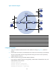
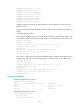

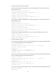
Table Of Contents
- Title Page
- Contents
- Multicast overview
- Configuring IGMP snooping
- Overview
- IGMP snooping configuration task list
- Configuring basic IGMP snooping functions
- Configuring IGMP snooping port functions
- Configuring IGMP snooping policies
- Displaying and maintaining IGMP snooping
- IGMP snooping configuration examples
- Troubleshooting IGMP snooping
- Configuring multicast routing and forwarding
- Configuring IGMP
- Configuring PIM
- Overview
- Configuring PIM-DM
- Configuring PIM-SM
- Configuring common PIM features
- Displaying and maintaining PIM
- PIM configuration examples
- Troubleshooting PIM
- Configuring MLD snooping
- Overview
- MLD snooping configuration task list
- Configuring basic MLD snooping functions
- Configuring MLD snooping port functions
- Configuring MLD snooping policies
- Displaying and maintaining MLD snooping
- MLD snooping configuration examples
- Troubleshooting MLD snooping
- Configuring IPv6 multicast routing and forwarding
- Configuring MLD
- Configuring IPv6 PIM
- PIM overview
- Configuring IPv6 PIM-DM
- Configuring IPv6 PIM-SM
- Configuring common IPv6 PIM features
- Displaying and maintaining IPv6 PIM
- IPv6 PIM configuration examples
- Troubleshooting IPv6 PIM
- Support and other resources
- Index
94
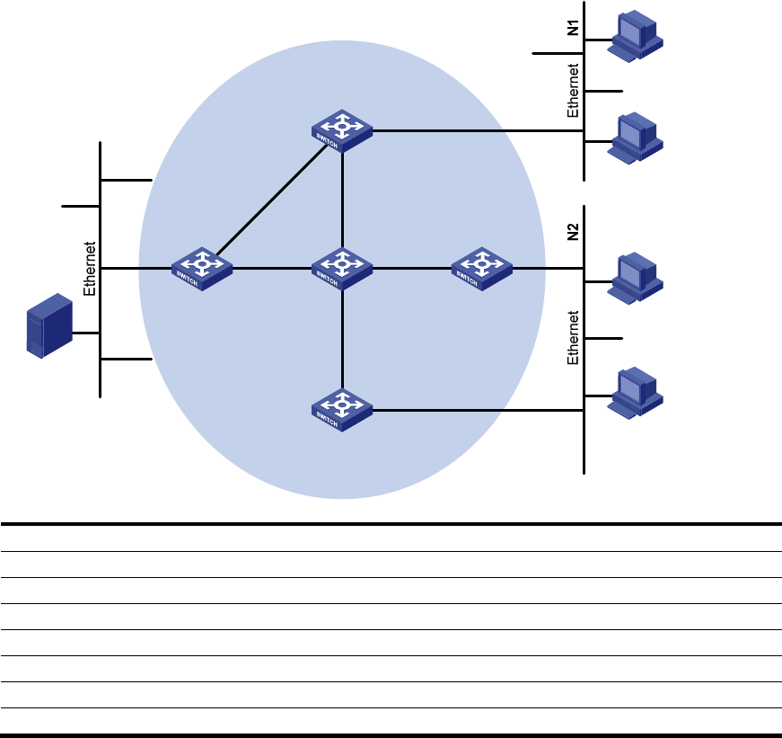
Figure 33 Network diagram
Device Interface IP address
Device
Interface
IP address
Switch A Vlan-int100 10.110.1.1/24 Switch D Vlan-int300 10.110.5.1/24
Vlan-int101 192.168.1.1
/
24
Vlan-int101 192.168.1.2
/
24
Vlan-int102 192.168.9.1
/
24
Vlan-int105 192.168.4.2
/
24
Switch B Vlan-int200 10.110.2.1/24 Switch E Vlan-int104 192.168.3.2/24
Vlan-int103 192.168.2.1
/
24
Vlan-int103 192.168.2.2/24
Switch C Vlan-int200 10.110.2.2
/
24
Vlan-int102 192.168.9.2
/
24
Vlan-int104 192.168.3.1/24 Vlan-int105 192.168.4.1/24
Configuration procedure
1. Assign an IP address and subnet mask to each interface according to Figure 33. (Details not
shown.)
2. Enable OSPF on all switches on the PIM-SM network to make sure the network-layer on the PIM-SM
network is interoperable and the routing information among the switches can be dynamically
updated. (Details not shown.)
3. Enable IP multicast routing, and enable IGMP and PIM-SM:
# On Switch A, enable IP multicast routing globally, enable IGMP on VLAN-interface 100, and
enable PIM-SM on each interface.
<SwitchA> system-view
[SwitchA] multicast routing-enable
[SwitchA] interface vlan-interface 100
[SwitchA-Vlan-interface100] igmp enable
Source
10.110.5.100/24
PIM-SM
Switch A
Switch B
Switch C
Switch D
Receiver
Host A
Host B
Host C
Host D
Receiver
Switch E
Vlan-int100
Vlan-int200
Vlan-int200
Vlan-int300
Vlan-int102
Vlan-int102
Vlan-i
nt1
01
Vlan-int10
1
Vlan-int103
Vlan-int103
Vlan-int104
Vlan-int104
Vlan-int105
Vlan-int105