
R21xx-HP FlexFabric 11900 IP Multicast Configuration Guide
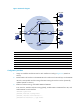

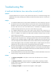
Table Of Contents
- Title Page
- Contents
- Multicast overview
- Configuring IGMP snooping
- Overview
- IGMP snooping configuration task list
- Configuring basic IGMP snooping functions
- Configuring IGMP snooping port functions
- Configuring IGMP snooping policies
- Displaying and maintaining IGMP snooping
- IGMP snooping configuration examples
- Troubleshooting IGMP snooping
- Configuring multicast routing and forwarding
- Configuring IGMP
- Configuring PIM
- Overview
- Configuring PIM-DM
- Configuring PIM-SM
- Configuring common PIM features
- Displaying and maintaining PIM
- PIM configuration examples
- Troubleshooting PIM
- Configuring MLD snooping
- Overview
- MLD snooping configuration task list
- Configuring basic MLD snooping functions
- Configuring MLD snooping port functions
- Configuring MLD snooping policies
- Displaying and maintaining MLD snooping
- MLD snooping configuration examples
- Troubleshooting MLD snooping
- Configuring IPv6 multicast routing and forwarding
- Configuring MLD
- Configuring IPv6 PIM
- PIM overview
- Configuring IPv6 PIM-DM
- Configuring IPv6 PIM-SM
- Configuring common IPv6 PIM features
- Displaying and maintaining IPv6 PIM
- IPv6 PIM configuration examples
- Troubleshooting IPv6 PIM
- Support and other resources
- Index
97
The source 1 and the source 2 send different multicast data to the multicast group 239.1.1.1. Host A
receives the multicast data only from the source 1, and Host B receives the multicast data only from the
source 2. The source 3 sends multicast data to the multicast group 224.1.1.1. Host C is a multicast receiver
f o r t h e m u l t ic a s t g ro u p 224 .1.1.1.
VLAN-interface 101 of Switch B acts as a C-BSR and a C-RP for admin-scoped zone 1, and
VLAN-interface 105 of Switch D acts as a C-BSR and a C-RP for admin-scoped zone 2, and both of the
two interfaces provide services for the multicast group range 239.0.0.0/8. VLAN-interface 109 of Switch
F acts as a C-BSR and a C-RP for the global-scoped zone, and it provides services for all the multicast
groups that are not in the range 239.0.0.0/8.
IGMPv2 runs between Switch A, Switch E, Switch I, and the receivers that directly connect to them,
respectively.
Figure 34 Network diagram
Device Interface IP address
Device
Interface
IP address
Switch A Vlan-int100 192.168.1.1/24 Switch D Vlan-int105 10.110.5.2/24
Vlan-int101 10.110.1.1
/
24
Vlan-int108 10.110.7.1
/
24
Switch B Vlan-int200 192.168.2.1
/
24
Vlan-int107 10.110.8.1
/
24
Vlan-int101 10.110.1.2/24 Switch E Vlan-int400 192.168.4.1/24
Vlan-int103 10.110.2.1
/
24
Vlan-int104 10.110.4.2
/
24
Vlan-int102 10.110.3.1
/
24
Vlan-int108 10.110.7.2
/
24
Switch C Vlan-int300 192.168.3.1/24 Switch F Vlan-int109 10.110.9.1/24
Vlan-int104 10.110.4.1
/
24
Vlan-int107 10.110.8.2
/
24
Vlan-int105 10.110.5.1
/
24
Vlan-int102 10.110.3.2
/
24
Vl
a
n-int10
4
Vl
an-
int103
Vlan-int300
Vlan-
i
nt10
4
Vlan-
i
nt
600
Vl
an-i
nt
103