
R21xx-HP FlexFabric 11900 IP Multicast Configuration Guide
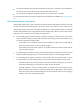
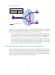
Table Of Contents
- Title Page
- Contents
- Multicast overview
- Configuring IGMP snooping
- Overview
- IGMP snooping configuration task list
- Configuring basic IGMP snooping functions
- Configuring IGMP snooping port functions
- Configuring IGMP snooping policies
- Displaying and maintaining IGMP snooping
- IGMP snooping configuration examples
- Troubleshooting IGMP snooping
- Configuring multicast routing and forwarding
- Configuring IGMP
- Configuring PIM
- Overview
- Configuring PIM-DM
- Configuring PIM-SM
- Configuring common PIM features
- Displaying and maintaining PIM
- PIM configuration examples
- Troubleshooting PIM
- Configuring MLD snooping
- Overview
- MLD snooping configuration task list
- Configuring basic MLD snooping functions
- Configuring MLD snooping port functions
- Configuring MLD snooping policies
- Displaying and maintaining MLD snooping
- MLD snooping configuration examples
- Troubleshooting MLD snooping
- Configuring IPv6 multicast routing and forwarding
- Configuring MLD
- Configuring IPv6 PIM
- PIM overview
- Configuring IPv6 PIM-DM
- Configuring IPv6 PIM-SM
- Configuring common IPv6 PIM features
- Displaying and maintaining IPv6 PIM
- IPv6 PIM configuration examples
- Troubleshooting IPv6 PIM
- Support and other resources
- Index
132
Multicast forwarding over a GRE tunnel
configuration example
Network requirements
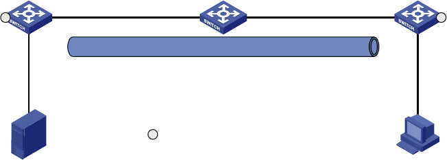
IPv6 multicast routing and IPv6 PIM-DM are enabled on Switch A and Switch C. Switch B does not
support IPv6 multicast. OSPFv3 is running on Switch A, Switch B, and Switch C.
Perform the configuration so that the receiver host can receive the IPv6 multicast data from the source.
Figure 41 Network diagram
Configuration procedure
1. Configure the IPv6 address and prefix length for each interface as shown in Figure 41. (Details not
shown.)
2. Enable OSPFv3 on the switches to make sure the network-layer among the switches is
interoperable and the routing information among the switches can be dynamically updated.
(Details not shown.)
3. Configure a GRE tunnel:
# Create service loopback group 1 on Switch A and specify its service type as Tunnel.
<SwitchA> system-view
[SwitchA] service-loopback group 1 type tunnel
# Disable STP and LLDP on interface Ten-GigabitEthernet 1/0/3 of Switch A, and add the
interface to service loopback group 1. Ten-GigabitEthernet 1/0/3 does not belong to VLAN 100
or VLAN 101.
[SwitchA] interface ten-gigabitethernet 1/0/3
[SwitchA-Ten-GigabitEthernet1/0/3] undo stp enable
[SwitchA-Ten-GigabitEthernet1/0/3] undo lldp enable
[SwitchA-Ten-GigabitEthernet1/0/3] port service-loopback group 1
IPv6 multicast router
Switch A
Vlan-int101
2001::1/64
Vlan-int102
3001::1/64
Vlan-int102
3001::2/64
Vlan-int101
2001::2/64
Source Receiver
4001::100/64
Vlan-int200
4001::1/64
1001::100/64
Vlan-int100
1001::1/64
GRE tunnel
Tunnel0
5001::1/64
Tunnel0
5001::2/64
IPv6 unicast router
Switch B
IPv6 multicast router
Switch C
Member port of the
service loopback group
XGE1/0/3 XGE1/0/3