
R21xx-HP FlexFabric 11900 IP Multicast Configuration Guide

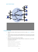
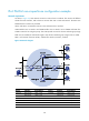
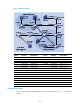
Table Of Contents
- Title Page
- Contents
- Multicast overview
- Configuring IGMP snooping
- Overview
- IGMP snooping configuration task list
- Configuring basic IGMP snooping functions
- Configuring IGMP snooping port functions
- Configuring IGMP snooping policies
- Displaying and maintaining IGMP snooping
- IGMP snooping configuration examples
- Troubleshooting IGMP snooping
- Configuring multicast routing and forwarding
- Configuring IGMP
- Configuring PIM
- Overview
- Configuring PIM-DM
- Configuring PIM-SM
- Configuring common PIM features
- Displaying and maintaining PIM
- PIM configuration examples
- Troubleshooting PIM
- Configuring MLD snooping
- Overview
- MLD snooping configuration task list
- Configuring basic MLD snooping functions
- Configuring MLD snooping port functions
- Configuring MLD snooping policies
- Displaying and maintaining MLD snooping
- MLD snooping configuration examples
- Troubleshooting MLD snooping
- Configuring IPv6 multicast routing and forwarding
- Configuring MLD
- Configuring IPv6 PIM
- PIM overview
- Configuring IPv6 PIM-DM
- Configuring IPv6 PIM-SM
- Configuring common IPv6 PIM features
- Displaying and maintaining IPv6 PIM
- IPv6 PIM configuration examples
- Troubleshooting IPv6 PIM
- Support and other resources
- Index
178
IPv6 PIM-SM non-scoped zone configuration example
Network requirements
As shown in Figure 54, VOD streams are sent to receiver hosts in multicast. The receivers of different
subnets form stub networks, and at least one receiver host exist in each stub network. The entire IPv6
PIM-SM domain contains only one BSR.
Host A and Host C are multicast receivers in the stub networks N1 and N2.
VLAN-interface 105 on Switch D and VLAN-interface 102 on Switch E act as C-BSRs and C-RPs. The
C-BSR on Switch E has a higher priority. The C-RPs provide services for the IPv6 multicast group range
FF0E::101/64. Modify the hash mask length to map the IPv6 multicast group range to the two C-RPs.
MLDv1 runs between Switch A and N1, and between Switch B, Switch C, and N2.
Figure 54 Network diagram
Device Interface IPv6 address
Device
Interface
IPv6 address
Switch A Vlan-int100 1001::1/64 Switch D Vlan-int300 4001::1/64
Vlan-int101 1002::1/64
Vlan-int101 1002::2
/
64
Vlan-int102 1003::1
/
64
Vlan-int105 4002::1/64
Switch B Vlan-int200 2001::1/64 Switch E Vlan-int104 3001::2/64
Vlan-int103 2002::1
/
64
Vlan-int103 2002::2
/
64
Switch C Vlan-int200 2001::2
/
64
Vlan-int102 1003::2
/
64
Vlan-int104 192.168.3.1/24 Vlan-int105 192.168.4.1/24
Ethernet
EthernetEthernet
N1N2
Vlan-
i
nt1
01
Vlan-int10
1