
R21xx-HP FlexFabric 11900 IP Multicast Configuration Guide

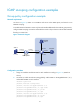
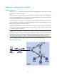
Table Of Contents
- Title Page
- Contents
- Multicast overview
- Configuring IGMP snooping
- Overview
- IGMP snooping configuration task list
- Configuring basic IGMP snooping functions
- Configuring IGMP snooping port functions
- Configuring IGMP snooping policies
- Displaying and maintaining IGMP snooping
- IGMP snooping configuration examples
- Troubleshooting IGMP snooping
- Configuring multicast routing and forwarding
- Configuring IGMP
- Configuring PIM
- Overview
- Configuring PIM-DM
- Configuring PIM-SM
- Configuring common PIM features
- Displaying and maintaining PIM
- PIM configuration examples
- Troubleshooting PIM
- Configuring MLD snooping
- Overview
- MLD snooping configuration task list
- Configuring basic MLD snooping functions
- Configuring MLD snooping port functions
- Configuring MLD snooping policies
- Displaying and maintaining MLD snooping
- MLD snooping configuration examples
- Troubleshooting MLD snooping
- Configuring IPv6 multicast routing and forwarding
- Configuring MLD
- Configuring IPv6 PIM
- PIM overview
- Configuring IPv6 PIM-DM
- Configuring IPv6 PIM-SM
- Configuring common IPv6 PIM features
- Displaying and maintaining IPv6 PIM
- IPv6 PIM configuration examples
- Troubleshooting IPv6 PIM
- Support and other resources
- Index
29
Static port configuration example
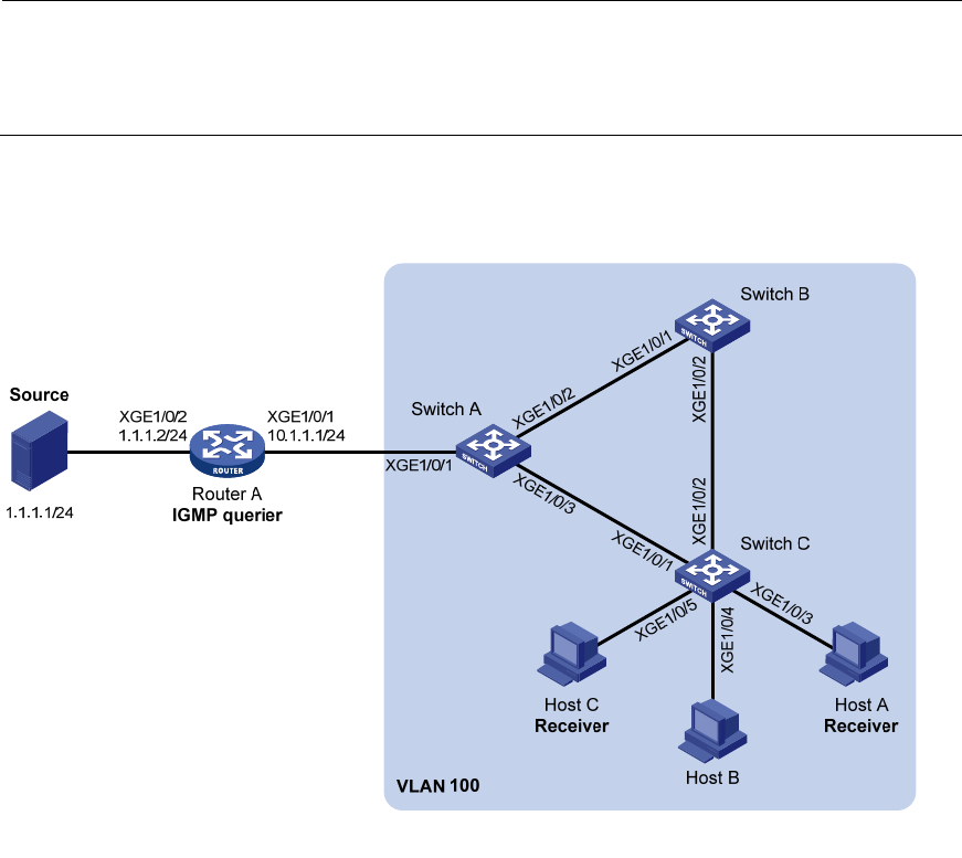
Network requirements
As shown in Figure 13, Router A runs IGMPv2 and serves as the IGMP querier, and Switch A, Switch B,
and Switch C run IGMPv2 snooping.
Host A and host C are permanent receivers of multicast group 224.1.1.1. Configure Ten-GigabitEthernet
1/0/3 and Ten-GigabitEthernet 1/0/5 on Switch C as static member ports for multicast group 224.1.1.1
to enhance the reliability of multicast traffic transmission.
Suppose the STP runs on the network. To avoid data loops, the forwarding path from Switch A to Switch
C is blocked under normal conditions, and multicast data flows to the receivers attached to Switch C only
along the path of Switch A—Switch B—Switch C.
Configure Ten-GigabitEthernet 1/0/3 on Switch A as a static router port, so that multicast data can flow
to the receivers nearly uninterruptedly along the path of Switch A—Switch C when the path of Switch
A—Switch B—Switch C is blocked.
NOTE:
If no static router port is configured, when the path of Switch A—Switch B—Switch C is blocked, at leas
t
one IGMP query-response cycle must be completed before the multicast data can flow to the receivers
along the new path of Switch A—Switch C, so multicast delivery is interrupted during this process.
For more information about the STP, see Layer 2—LAN Switching Configuration Guide.
Figure 13 Network diagram