HP FlexFabric 11900 Switch Series IRF Command Reference Part number: 5998-4074 Software version: Release 2105 and later Document version: 6W100-20130515
Legal and notice information © Copyright 2013 Hewlett-Packard Development Company, L.P. No part of this documentation may be reproduced or transmitted in any form or by any means without prior written consent of Hewlett-Packard Development Company, L.P. The information contained herein is subject to change without notice.
Contents IRF configuration commands ······································································································································· 1 chassis convert mode irf ·········································································································································· 1 display irf ································································································································································
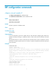
IRF configuration commands chassis convert mode irf Use chassis convert mode irf to enable IRF mode. Use undo chassis convert mode to restore standalone mode. Syntax chassis convert mode irf undo chassis convert mode Default The device operates in standalone mode. Views System view Predefined user roles network-admin Usage guidelines To set up an IRF fabric, place all its member devices in IRF mode after configuring their member IDs, priorities, and IRF port settings.
The device will switch to stand-alone mode and reboot. You are recommended to save the current running configuration and specify the configuration file for the next startup. Continue? [Y/N]:y Do you want to convert the content of the next startup configuration file flash:/startup.cfg to make it available in stand-alone mode? [Y/N]:y Please wait... Saving the converted configuration file to the main board succeeded. Chassis 2 Slot 1: Saving the converted configuration file succeeded.
Field Description Role of the MPU in the IRF fabric: Role • Standby—Standby MPU for the global active MPU. • Master—Global active MPU. • Loading—Standby MPU for the global active MPU. The standby MPU is loading software images. Priority IRF member priority. CPU-MAC MAC address of the CPU on the MPU. Description you have configured for the member device. Description • If no description is configured, this field displays a dashed line (-----).
network-operator Examples # In standalone mode, display the basic IRF settings of the device. display irf configuration MemberID Priority IRF-Port1 -- 1 IRF-Port2 disable disable # In IRF mode, display all members' basic IRF settings.
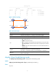
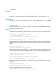
Topology Info ------------------------------------------------------------------------IRF-Port1 IRF-Port2 MemberID Link neighbor Link neighbor Belong To 1 UP 3 UP 2 00e0-fc0f-8c0f 2 UP 1 UP 4 00e0-fc0f-8c0f 3 UP 4 UP 1 00e0-fc0f-8c0f 4 UP 2 UP 3 00e0-fc0f-8c0f Figure 1 IRF fabric topology 1 2 IRF-port1/2 IRF-port2/1 IRF-port1/1 IRF-port2/2 IRF-port3/2 IRF-port4/1 IRF-port3/1 IRF-port4/2 3 4 Table 3 Command output Field Description IRF-Port 1 Information about IRF
Predefined user roles network-admin network-operator Parameters irf-port: Displays IRF port-specific load sharing modes. member-id/port-number: Specifies an IRF port number. The member-id argument represents an IRF member ID. The port-number argument represents the index number (1 or 2) of the IRF port on the member device. Usage guidelines To display the global load sharing mode for IRF links, execute this command without the irf-port [ member-id/port-number ] option.
irf-port1/1 Load-Sharing Mode: destination-mac address, source-mac address irf-port1/2 Load-Sharing Mode: Layer 2 traffic: destination-mac address, source-mac address Layer 3 traffic: destination-ip address, source-ip address Layer 4 traffic: destination-port, source-port Table 4 Command output Field Description Global load sharing mode for IRF links: irf-port Load-Sharing Mode • If no global IRF link load sharing mode has been configured, the default global load sharing mode applies.
Examples # Display brief MAD information. display mad MAD LACP disabled. MAD BFD disabled. # Display detailed MAD information. display mad verbose Excluded ports(configurable): Ten-GigabitEthernet2/1/0/2 Ten-GigabitEthernet2/1/0/3 Excluded ports(can not be configured): Ten-GigabitEthernet2/2/0/25 Ten-GigabitEthernet3/2/0/26 MAD enabled aggregation port: Bridge-Aggregation2 MAD BFD enabled interface: Vlan-interface2 mad ip address 10.0.0.2 255.255.0.0 member 2 mad ip address 10.0.0.
Default This function is disabled. To complete an IRF merge, you must manually reboot the IRF fabric that has failed in the master election. Views System view Predefined user roles network-admin Usage guidelines To avoid an auto merge failure, make sure the auto merge function is enabled on both IRF fabrics that are merging. This command is available in IRF mode.
Before enabling software auto-update, make sure the device you are adding to the IRF fabric has sufficient storage space for the new software images. If sufficient storage space is not available, the device automatically deletes the current software images. If the reclaimed space is still insufficient, the device cannot complete the auto-update, and you must reboot the device and access the Boot menu to delete files.
An IRF fabric has only one IRF domain ID. You can change the IRF domain ID with the following commands: irf domain or mad enable command. The IRF domain IDs configured with these commands overwrite each other. Examples # Set the IRF domain ID to 30. system-view [Sysname] irf domain 30 irf link-delay Use irf link-delay to set a delay for the IRF ports to report a link down event. Use undo irf link-delay to restore the default.
irf mac-address persistent Use irf mac-address persistent to configure IRF bridge MAC persistence so the IRF fabric continues to use the bridge MAC address of the old master as its bridge MAC address for a period of time after a master re-election. Use undo irf mac-address persistent to enable the IRF fabric to change its bridge MAC address as soon as the master leaves.
irf member Use irf member to assign a member ID to the device in standalone mode. Use undo irf member to restore the default. Syntax irf member member-id undo irf member Default The device operates in standalone mode and has no member ID. Views System view Predefined user roles network-admin Parameters member-id: Assigns an IRF member ID to the device. The value range is 1 to 4. Usage guidelines You must assign an IRF member ID to a device before enabling its IRF mode.
Predefined user roles network-admin Parameters member-id: Specifies the ID of an IRF member. text: Configures the IRF member description, a string of 1 to 127 characters. Usage guidelines Configure a description to identify the physical location or purpose of an IRF member for easy maintenance. This command is available in IRF mode. Changing the operating mode from IRF to standalone can cause loss of the IRF member description even if you have saved the configuration.
system-view [Sysname] irf member 2 priority 32 Related commands irf priority irf member renumber Use irf member renumber to change the member ID of a device in the IRF fabric. Use undo irf member renumber to restore the previous IRF member ID of the device. Syntax irf member member-id renumber new-member-id undo irf member member-id renumber Default In standalone mode, the device has no member ID. In IRF mode, the device by default uses the member ID set by using the irf member command.
[Sysname] undo irf member 2 renumber Warning: Renumbering the member ID may result in configuration change or loss. Continue?[Y/N]y If you reboot the device after executing the irf member 2 renumber 4 command, the device member ID changes to 4 at system reboot. Using undo irf member 2 renumber cannot restore the member ID to 2. Related commands irf member irf priority Use irf priority to assign an IRF member priority to a device in standalone mode. Use undo irf priority to restore the default.
Syntax In system view: irf-port global load-sharing mode { destination-ip | destination-mac | ingress-port | source-ip | source-mac } * undo irf-port global load-sharing mode In IRF port view: irf-port load-sharing mode { destination-ip | destination-mac | ingress-port | source-ip | source-mac } * undo irf-port load-sharing mode Default The following are criteria for distributing different types of packets across IRF links: • TCP/UDP packets—Source and destination TCP/UDP port numbers.
# Configure IRF-port 1/1 to distribute traffic across its physical links based on destination MAC address. system-view [Sysname] irf-port 1/1 [Sysname-irf-port1/1] irf-port load-sharing mode destination-mac irf-port member-id/port-number Use irf-port member-id/port-number to enter IRF port view in IRF mode. Use undo irf-port member-id/port-number to removing all port bindings on an IRF port in IRF mode.
Predefined user roles network-admin Parameters port-number: Specifies an IRF port number, which must be 1 or 2. Usage guidelines To set up an IRF link between two devices, you must enter IRF port view to bind physical ports to the IRF port used by each device for IRF connection. Before removing all port bindings on an IRF port, shut down all its physical ports. Examples # In standalone mode, enter IRF-port 1 view.
Info : You are recommended to save the configuration now; otherwise, it will be lost after system reboot. [Sysname-irf-port1/2] quit [Sysname] interface ten-gigabitEthernet 1/1/0/27 [Sysname-Ten-GigabitEthernet1/1/0/27] undo shutdown [Sysname-Ten-GigabitEthernet1/1/0/27] quit # Save the configuration so the IRF port settings can take effect after the device reboots. [Sysname] save The current configuration will be written to the device. Are you sure? [Y/N]:y Please input the file name(*.
• Do not enable the spanning tree function on any port in a BFD MAD VLAN. The MAD function is mutually exclusive with the spanning tree function. • Do not bind the VLAN interface to any VPN. The MAD function is mutually exclusive with VPN. • To avoid problems, only use the mad ip address command to configure IP addresses on the BFD MAD-enabled VLAN interface. For example, an IP address configured with the ip address command or a VRRP virtual IP address can cause problems.
Examples # Enable LACP MAD on Bridge-Aggregation 1, a Layer 2 dynamic aggregate interface. system-view [Sysname] interface bridge-aggregation 1 [Sysname-Bridge-Aggregation1] mad enable You need to assign a domain ID (range: 0-4294967295) [Current domain is: 0]: 1 The assigned domain ID is: 1 MAD LACP only enable on dynamic aggregation interface.
system-view [Sysname] mad exclude interface ten-gigabitethernet 2/5/0/1 mad ip address Use mad ip address to assign a MAD IP address to an IRF member on a VLAN interface for BFD MAD. Use undo mad ip address to delete a MAD IP address. Syntax mad ip address ip-address { mask | mask-length } member member-id undo mad ip address ip-address { mask | mask-length } member member-id Default No MAD IP address is configured on any VLAN interface.
# Assign a MAD IP address to IRF member 2 on VLAN-interface 3. [Sysname-Vlan-interface3] mad ip address 192.168.0.2 255.255.255.0 member 2 Related commands mad bfd enable mad restore Use mad restore to restore the normal MAD state of the IRF fabric in Recovery state.
Parameters interface-type interface-number: Specifies a physical port by its type and number. interface-name: Specifies a physical port in the interface-typeinterface-number format. No space is allowed between the interface-type and interface-number arguments. mode: Specifies a binding mode for the physical IRF port. • enhanced: Sets the binding mode to enhanced. • normal: Sets the binding mode to normal.
Support and other resources Contacting HP For worldwide technical support information, see the HP support website: http://www.hp.
Conventions This section describes the conventions used in this documentation set. Command conventions Convention Description Boldface Bold text represents commands and keywords that you enter literally as shown. Italic Italic text represents arguments that you replace with actual values. [] Square brackets enclose syntax choices (keywords or arguments) that are optional. { x | y | ... } Braces enclose a set of required syntax choices separated by vertical bars, from which you select one.
Network topology icons Represents a generic network device, such as a router, switch, or firewall. Represents a routing-capable device, such as a router or Layer 3 switch. Represents a generic switch, such as a Layer 2 or Layer 3 switch, or a router that supports Layer 2 forwarding and other Layer 2 features. Represents an access controller, a unified wired-WLAN module, or the switching engine on a unified wired-WLAN switch. Represents an access point.
Index CDIMPSW irf priority,16 C irf-port load-sharing mode,16 chassis convert mode irf,1 irf-port member-id/port-number,18 D irf-port port-number,18 display irf,2 irf-port-configuration active,19 display irf configuration,3 M display irf topology,4 mad bfd enable,20 display irf-port load-sharing mode,5 mad enable,21 display mad,7 mad exclude interface,22 Documents,26 mad ip address,23 I mad restore,24 irf auto-merge enable,8 P irf auto-update enable,9 port group interface,24 irf dom