HP FlexFabric 11900 Switch Series IRF Configuration Guide Part number: 5998-4058 Software version: Release 2105 and later Document version: 6W100-20130515
Legal and notice information © Copyright 2013 Hewlett-Packard Development Company, L.P. No part of this documentation may be reproduced or transmitted in any form or by any means without prior written consent of Hewlett-Packard Development Company, L.P. The information contained herein is subject to change without notice.
Contents IRF overview ································································································································································· 1 Hardware compatibility ···················································································································································· 1 IRF benefits ···········································································································································
Accessing the IRF fabric ················································································································································ 17 Configuring IRF member devices in IRF mode ············································································································ 17 Assigning an IRF domain ID to the IRF fabric ····································································································· 17 Changing the member ID of a device
IRF overview The HP Intelligent Resilient Framework (IRF) technology creates a large IRF fabric from multiple devices to provide data center class availability and scalability. IRF virtualization technology offers processing power, interaction, unified management, and uninterrupted maintenance of multiple devices. This book describes IRF concepts and guides you through the IRF setup procedure. Hardware compatibility • An HP 11900 IRF fabric can have up to four chassis.
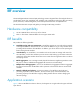
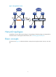
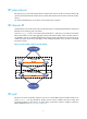
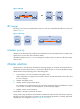
Figure 1 IRF application scenario Network topologies An IRF fabric can use a daisy chain topology or a ring topology. Full mesh topology is not supported. For information about connecting IRF member devices, see "Connecting physical IRF ports." Basic concepts This section uses Figure 2 to describe the basic concepts that you might encounter when you work with IRF.
Figure 2 Two-chassis IRF fabric implementation schematic diagram In this figure, Device A and Device B form a two-chassis IRF fabric that has four MPUs (one active and three standbys) and two times the number of interface cards that a single device provides. The IRF fabric manages the physical and software resources of Device A and Device B in a centralized manner. Operating mode The device operates in one of the following modes: • Standalone mode—The device cannot form an IRF fabric with other devices.
IRF member ID An IRF fabric uses member IDs to uniquely identify and manage its members. If two devices have the same IRF member ID, they cannot form an IRF fabric. If the IRF member ID of a device has been used in an IRF fabric, the device cannot join the fabric. Member ID information is included as the first part of interface numbers and file paths to uniquely identify interfaces and files in an IRF fabric.
IRF physical port IRF physical ports connect IRF member devices and must be bound to an IRF port. They forward the IRF protocol packets between IRF member devices and the data packets that must travel across IRF member devices. All 10-GE and 40-GE ports on the device can be used for IRF connection. IRF domain ID One IRF fabric forms one IRF domain. IRF uses IRF domain IDs to uniquely identify IRF fabrics and prevent IRF fabrics from interfering with one another.
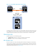
Figure 4 IRF split IRF merge IRF merge occurs when two split IRF fabrics reunite or when two independent IRF fabrics are united, as shown in Figure 5. Figure 5 IRF merge IRF 1 IRF IRF 2 + Device A XGE1/3/0/1 = Device B XGE2/3/0/1 IRF link Device A Device B Member priority Member priority determines the possibility of a member device to be elected the master. A member with higher priority is more likely to be elected the master. The default member priority is 1.
After a master election, all subordinate devices reboot with the configuration on the master. The subordinate members' configuration files do not take effect in IRF mode. Their configuration files take effect after their operating mode is converted to standalone. IRF multi-active detection An IRF link failure causes an IRF fabric to split in two IRF fabrics operating with the same Layer 3 configurations, including the same IP address.
If the IRF fabric in Recovery state fails before the failure is recovered, repair the failed IRF fabric and the failed IRF link. If the IRF fabric in Active state fails before the failure is recovered, first enable the IRF fabric in Recovery state to take over the active IRF fabric and protect services from being affected. After that, recover the MAD failure.
BFD MAD BFD MAD can work with or without intermediate devices. Figure 7 shows a typical BFD MAD application scenario. To use BFD MAD: • Set up dedicated BFD MAD link between each pair of IRF members or between each IRF member and the intermediate device. Do not use the BFD MAD links for any other purpose. • Assign the ports connected by BFD MAD links to the same VLAN, create a VLAN interface for the VLAN, and assign a MAD IP address to each member on the VLAN interface.
Configuring IRF General restrictions and configuration guidelines To ensure a successful IRF setup, read the configuration restrictions and guidelines carefully before you connect and set up an IRF fabric. Software requirements All IRF member devices must run the same system software image version. MPU and IRF physical port restrictions MPU restrictions Make sure every IRF member has at least one MPU. Physical port binding restrictions • Use 10-GE or 40-GE ports for IRF connection.
IRF link redundancy • For link redundancy and load sharing, bind up to eight physical ports to one IRF port. • Physical ports bound to an IRF port can be located on different cards. • HP recommends using multicard IRF links to avoid a card removal causing an IRF split. ECMP route restrictions To form an IRF fabric, all member devices must have the same setting for the maximum number of ECMP routes. For more information about configuring ECMP, see Layer 3—IP Routing Configuration Guide.
Setup and configuration task list HP recommends the following IRF fabric setup and configuration procedure: Setup and configuration procedure Remarks (Required.) Planning the IRF fabric setup 1. N/A (Required.) Preconfiguring IRF member devices in standalone mode: 2. { Assigning a member ID to each IRF member device { Specifying a priority for each member device { Binding physical ports to IRF ports Perform this task on each member device before the IRF mode is enabled. 3. (Required.
Preconfiguring IRF member devices in standalone mode Perform the tasks in this section on every IRF member device. These settings take effect on each member device after their operating mode changes to IRF. Assigning a member ID to each IRF member device IMPORTANT: If a two-chassis IRF fabric has OAA cards, you must assign member ID 1 or 2 to the member device that holds the cards. A device by default operates in standalone mode without an IRF member ID.
Binding physical ports to IRF ports To establish an IRF connection between two devices, you must bind at least one physical port to IRF-port 1 on one device and to IRF-port 2 on the other. For link redundancy and load sharing, bind multiple physical ports to one IRF port. In standalone mode, binding a physical port to an IRF port does not affect the current configuration of the port.
Step Command Remarks By default, no physical ports are bound to any IRF port. Bind a physical IRF port to the IRF port. 3. port group interface interface-type interface-number [ mode { enhanced | normal } ] Repeat this step to assign more physical ports to an IRF port. Each IRF port can have up to eight physical ports. Physical ports bound to an IRF port can be located on different cards.
Figure 8 Connecting IRF physical ports Connect the devices into a daisy chain topology or a ring topology. A ring topology is more reliable (see Figure 9). In ring topology, the failure of one IRF link does not cause the IRF fabric to split as in daisy chain topology. Instead, the IRF fabric changes to a daisy chain topology without interrupting network services. To use the ring topology, you must have at least three member devices.
Step 2. Set the operating mode to IRF mode. Command Remarks chassis convert mode irf The default operating mode is standalone mode. After you change the operating mode, the device automatically reboots to validate the change. During the reboot, you can choose to have the system automatically convert the startup configuration file to prevent some slot- or interface-related configurations from becoming invalid.
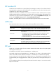
LACP MAD packet, it looks at the domain ID in the packet to see whether the packet is from the local IRF fabric or from a different IRF fabric. Then, the device can handle the packet correctly. Figure 10 A network that comprises two IRF domains Core network Device A IRF 1 (domain 10) Device B IRF link Device c IRF 2 (domain 20) Device D IRF link Access network To assign a domain ID to an IRF fabric: Step Command Remarks 1. Enter system view. system-view N/A 2.
If you save the current configuration and reboot the device, the new member ID takes effect and all • its physical resources are identified by the new member ID. In the configuration file, only the IRF port numbers, configurations on IRF ports, and member priority still take effect. All other member ID-related settings, including settings on the physical IRF port and chassis ID, no longer take effect and must be reconfigured.
WARNING! If you are using a 40-GE port for IRF connection, HP recommends completing the port split or combination operation before adding the switch to an IRF fabric. You can use the using tengige command or the using fortygige command to split 40-GE QSFP+ ports into 10-GE ports or recombine 10-GE ports into 40-GE ports. These operations require a card reboot and might cause an IRF fabric topology change. An IRF port can have up to eight physical ports.
Step Command Remarks By default, no physical ports are bound to any IRF port. 6. Bind each physical port to the IRF port. port group interface interface-type interface-number [ mode { enhanced | normal } ] Repeat this step to assign multiple physical ports to the IRF port for link redundancy. You can bind up to eight physical ports to an IRF port. The binding attempt will fail if you have bound eight physical ports to the IRF port. Make sure the two ends of an IRF link use the same binding mode. 7.
Enabling IRF auto merge When two IRF fabrics merge, you must reboot the member devices in the IRF fabric that fails in the master election. The auto merge function enables the IRF fabric to automatically reboot all its member devices to complete the merge. This function can work only when it is enabled on both IRF fabrics that are merging. The IRF auto merge function does not take effect on the IRF fabric merge caused by binding a physical port to an IRF port in IRF mode.
Configuring the global load sharing mode Step 1. 2. Enter system view. Configure the global IRF link load sharing mode.
Depending on your network condition, enable the IRF fabric to preserve or change its bridge MAC address after the master leaves. Available options include: irf mac-address persistent timer—Bridge MAC address of the IRF fabric is retained for 6 minutes • after the master leaves. If the master does not return before the timer expires, the IRF fabric uses the bridge MAC address of the new master as its bridge MAC address.
To synchronize software from the active MPU to the standby MPU in standalone mode, use the undo version check ignore and version auto-update enable commands. For more information, see Fundamentals Configuration Guide. To synchronize software from the global active MPU to other MPUs in an IRF fabric, use the software auto-update function in this section. The software auto-update function automatically propagates the software images of the master to all members in the IRF fabric.
To set the IRF link down report delay: Step 1. Enter system view. Command Remarks system-view N/A The default IRF link down report delay is 4 seconds. 2. Set the IRF link down report delay. irf link-delay interval If your IRF fabric requires a quick master/subordinate or IRF link switchover or has deployed the BFD or GR feature, HP recommends setting the delay to 0 seconds. If the CFD feature is used in the IRF fabric, make sure the delay interval is smaller than the maximum CCM lifetime.
MAD mechanism Advantages Disadvantages Application scenario • Suitable for various • Requires MAD dedicated physical ports and Layer 3 interfaces, which cannot be used for transmitting user traffic. • Detection speed is fast. • No intermediate device is BFD MAD network scenarios. • If no intermediate device is used, this mechanism is only suitable for IRF fabrics that have a small number of members that are geographically close to one another. • If no intermediate device required.
Step Command Remarks 5. Enable LACP MAD. mad enable By default, LACP MAD is disabled. 6. Return to system view. quit N/A • Enter interface range view: { 7. Enter Ethernet interface view or interface range view.
Step Command Remarks 1. Enter system view. system-view N/A 2. Assign a domain ID to the IRF fabric. irf domain domain-id By default, the domain ID of an IRF fabric is 0. 3. Create a new VLAN dedicated to BFD MAD. vlan vlan-id The default VLAN on the device is VLAN 1. 4. Return to system view. quit N/A • Enter interface range view: { 5. Enter Ethernet interface view or interface range view.
Excluding a port from the shutdown action upon detection of multi-active collision By default, all ports except the console and physical IRF ports automatically shut down when the IRF fabric transits to the Recovery state. You can exclude a port from the shutdown action for management or other special purposes. For example: • Exclude a port from the shutdown action, so you can Telnet to the port for managing the device.
If the Active-state fabric has failed, for example, because of device or link failures, before the IRF link is recovered (see Figure 12), use the mad restore command on the Recovery-state fabric to change its state to Active to take over. After you repair the IRF link, the two parts merge into a unified IRF fabric. Figure 12 Active-state IRF fabric fails before the IRF link is recovered To manually recover an IRF fabric in Recovery state: Step Command 1. Enter system view. system-view 2.
Task Command Display the load sharing mode for IRF links. display irf-port load-sharing mode [ irf-port [ member-id/port-number ] ] Display MAD configuration. display mad [ verbose ] Configuration examples This section provides IRF configuration examples for two-chassis and four-chassis IRF fabrics that use different MAD mechanisms.
system-view [Sysname] irf member 1 Info: Member ID change will take effect after the member reboots and operates in IRF mode.
# Connect the two devices as shown in Figure 13. # Enable IRF mode. system-view [Sysname] chassis convert mode irf The device will switch to IRF mode and reboot. You are recommended to save the current running configuration and specify the configuration file for the next startup. Continue? [Y/N]:y Do you want to convert the content of the next startup configuration file flash:/startup.cfg to make it available in IRF mode? [Y/N]:y Please wait...
[Sysname] interface gigabitethernet 4/0/1 [Sysname-GigabitEthernet4/0/1] port link-aggregation group 2 [Sysname-GigabitEthernet4/0/1] quit [Sysname] interface gigabitethernet 4/0/2 [Sysname-GigabitEthernet4/0/2] port link-aggregation group 2 5. Recover the IRF fabric after LACP MAD detects an IRF split: When the IRF links fail, the system outputs IRF link problem and card failure error messages.
*+2 1 Master 1 00e0-fc0f-8c20 ----- -------------------------------------------------* indicates the device is the master. + indicates the device through which the user logs in. The Bridge MAC of the IRF is: 0023-895f-954f Auto upgrade : yes Mac persistent : always Domain ID : 1 Auto merge : no BFD MAD-enabled IRF configuration example for a two-chassis IRF fabric Network requirements Set up an IRF fabric at the distribution layer of the network in Figure 14.
Configuration procedure 1. Configure Device A: # Assign member ID 1 to Device A and bind Ten-GigabitEthernet 3/0/1 to IRF-port 2. system-view [Sysname] irf member 1 Info: Member ID change will take effect after the member reboots and operates in IRF mode.
[Sysname-irf-port1] quit [Sysname] interface ten-gigabitethernet 3/0/1 [Sysname-Ten-GigabitEthernet3/0/1] undo shutdown [Sysname-Ten-GigabitEthernet3/0/1] quit # Save the configuration. [Sysname] quit save # Connect the two devices as shown in Figure 14. # Enable IRF mode. system-view [Sysname] chassis convert mode irf The device will switch to IRF mode and reboot. You are recommended to save the current running configuration and specify the configuration file for the next startup.
detected, please fix it. Because it has a higher member ID than Device A, Device B transits to the Recovery state and shuts down all its ports except those excluded from the shutdown action. # Repair the IRF link. (Details not shown.) When the IRF link is recovered, the system prompts you to reboot the IRF system. %May 6 15:12:52:935 2010 HP STM/6/STM_LINK_STATUS_UP: IRF port 1 is up. %May 6 15:13:02:828 2010 HP STM/4/STM_MERGE_NEED_REBOOT: IRF merge occurs and the IRF system needs a reboot.
Figure 15 Network diagram Configuration procedure 1. Identify the master. display irf MemberID Slot Role *+1 0 Master 1 1 2 0 2 1 Priority CPU-Mac Description 1 00e0-fc0a-15e0 DeviceA Standby 1 00e0-fc0f-8c02 DeviceA Standby 1 00e0-fc0f-15e1 DeviceB Standby 1 00e0-fc0f-15e2 DeviceB -------------------------------------------------- * indicates the device is the master. + indicates the device through which the user logs in.
[IRF] save The current configuration will be written to the device. Are you sure? [Y/N]:y Please input the file name(*.cfg)[flash:/startup.cfg] (To leave the existing filename unchanged, press the enter key): flash:/startup.cfg exists, overwrite? [Y/N]:y Validating file. Please wait..................................... The current configuration is saved to the active main board successfully. Configuration is saved to device successfully. 5. Change the operating mode of Device A to standalone.
Figure 16 Network diagram before IRF deployment Figure 17 Network diagram after IRF deployment Configuration procedure 42
IMPORTANT: For two neighboring IRF members, IRF links must be bound to IRF-port 1 on one member and to IRF-port 2 on the other. 1. Configure Device A: # Assign member ID 1 and priority 12 to Device A. system-view [Sysname] irf member 1 [Sysname] irf priority 12 # Bind Ten-GigabitEthernet 3/0/2 and Ten-GigabitEthernet 3/0/1 to IRF-port 1 and IRF-port 2, respectively.
[Sysname-irf-port2] quit # Enable enhanced IRF mode. [Sysname] irf mode enhanced # Save the configuration. [Sysname] save # Connect Device B to Device A as shown in Figure 17. Log in to Device B. # Enable IRF mode. system-view [Sysname] chassis convert mode irf The device will switch to IRF mode and reboot. You are recommended to save the current running configuration and specify the configuration file for the next startup.
Do you want to convert the content of the next startup configuration file flash:/startup.cfg to make it available in IRF mode? [Y/N]:y Please wait... Saving the converted configuration file to the main board succeeded. Slot 1: Saving the converted configuration file succeeded. Now rebooting, please wait... Device C reboots to join the IRF fabric. 4. Configure Device D: # Assign member ID 4 and member priority 2 to Device D.
Support and other resources Contacting HP For worldwide technical support information, see the HP support website: http://www.hp.
• HP manuals http://www.hp.com/support/manuals • HP download drivers and software http://www.hp.com/support/downloads • HP software depot http://www.software.hp.com • HP Education http://www.hp.com/learn Conventions This section describes the conventions used in this documentation set. Command conventions Convention Description Boldface Bold text represents commands and keywords that you enter literally as shown. Italic Italic text represents arguments that you replace with actual values.
Convention Description An alert that provides helpful information. TIP Network topology icons Represents a generic network device, such as a router, switch, or firewall. Represents a routing-capable device, such as a router or Layer 3 switch. Represents a generic switch, such as a Layer 2 or Layer 3 switch, or a router that supports Layer 2 forwarding and other Layer 2 features. Represents an access controller, a unified wired-WLAN module, or the switching engine on a unified wired-WLAN switch.
Index accessing IRF fabric (2 chassis), 32 IRF fabric, 17 IRF fabric (4 chassis), 32, 41 active IRF global link load sharing mode, 23 IRF active MPU, 4 IRF LACP MAD (2 chassis fabric), 32 adding IRF LACP MAD (IRF mode), 27 IRF physical ports (IRF mode), 19 IRF link load sharing mode (IRF mode), 22 application scenario IRF MAD (IRF mode), 26 IRF, 1 IRF member device (IRF mode), 17 IRF BFD MAD, 9 IRF member device description (IRF mode), 22 IRF LACP MAD, 8 IRF port-specific load sharing cri
IRF master election, 6 IRF configuration (4 chassis), 32, 41 IRF member configuration (IRF mode), 17 IRF device member priority (standalone mode), 13 IRF member configuration (standalone mode), 13 IRF domain ID, 5 IRF member device description (IRF mode), 22 IRF fabric access, 17 IRF member ID, 4 IRF fabric domain ID assignment (IRF mode), 17 IRF member ID assignment (standalone mode), 13 IRF fabric recovery, 30 IRF member priority, 6 IRF failure recovery, 7 IRF member priority (standalone mod
auto merge (IRF mode), 22 MPU restrictions, 10 basic concepts, 2 MPU role, 4 BFD MAD, 9 network topologies, 2 BFD MAD configuration (2 chassis fabric), 36 next startup configuration file save (standalone BFD MAD configuration (IRF mode), 28 mode), 15 bridge MAC persistence (IRF mode), 23 operating mode set, 16 configuration, 10, 12 operating modes, 3 device member ID change (IRF mode), 18 overview, 1 device member priority (standalone mode), 13 physical port, 5 displaying fabric, 31 physi
BFD. See BFD MAD IRF LACP MAD configuration (IRF mode), 27 detection, 7 IRF link down report delay (IRF mode), 25 handling procedure, 7 IRF MAD, 7 IRF fabric recovery, 30 IRF MAD configuration (IRF mode), 26 IRF fabric split, 7 IRF MAD handling procedure, 7 IRF MAD configuration (IRF mode), 26 IRF master election, 6 LACP.
physical port to IRF port bind (standalone mode), preconfiguring IRF member device (standalone 14 mode), 13 preconfiguring recovering IRF fabric, 30 IRF member device (standalone mode), 13 restoring IRF standalone mode (2 chassis fabric), priority 39 IRF device member priority (standalone mode), 13 saving IRF member, 6 IRF next startup configuration file (standalone mode), 15 IRF member priority change (IRF mode), 19 setting IRF link down report delay (IRF mode), 25 procedure setting I
IRF LACP MAD, 8 topology IRF MAD, 7 IRF application scenario, 1 IRF MAD detection, 7 IRF BFD MAD configuration (2 chassis fabric), 36 IRF MAD handling procedure, 7 IRF configuration, 10, 12 IRF master election, 6 IRF fabric configuration (2 chassis), 32 standby IRF fabric configuration (4 chassis), 32, 41 IRF standby MPU, 4 IRF LACP MAD configuration (2 chassis fabric), 32 switching IRF master election, 6 IRF master election, 6 IRF networks, 2 synchronizing IRF software IRF overview, 1 a