
R21xx-HP FlexFabric 11900 IRF Configuration Guide

15
Ste
p
Command
Remarks
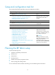
3. Bind a physical IRF port to
the IRF port.
port group interface interface-type
interface-number [ mode { enhanced |
normal } ]
By default, no physical ports are
bound to any IRF port.
Repeat this step to assign more
physical ports to an IRF port.
Each IRF port can have up to
eight physical ports.
Physical ports bound to an IRF
port can be located on different
cards.
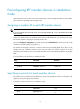
Saving configuration to the next-startup
configuration file
Save the running configuration before converting to the IRF mode. The mode change requires a reboot,
which can cause all unsaved settings to be lost.
Perform the following task in any view:
Task Command
Save the running configuration to
the next-startup configuration file.
save [ safely ] [ backup | main ] [ force ]
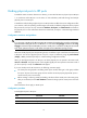
Connecting physical IRF ports
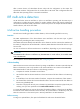
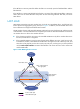
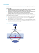
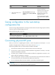
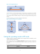
When you connect two neighboring IRF members, connect the physical ports of IRF-port 1 on one
member to the physical ports of IRF-port 2 on the other, as shown in Figure 8.
F
ollow these guidelines when you select transceiver modules and cables:
• The transceiver modules at the two ends of an IRF link must be the same type.
• For SFP+ ports, use SFP+ transceiver modules and fibers for long-distance connection, or use SFP+
cables for short-distance connection.
• For QSFP+ ports, use QSFP+ transceiver modules and fibers for long-distance connection, or use
QSFP+ cables for short-distance connection.
• When connecting SFP+ transceiver modules, connect the transmit port of the transceiver module at
one end to the receive port of the transceiver module at the other end.
• For more information about transceiver modules, see the device installation guide.
IMPORTANT:
No intermediate devices are allowed between neighboring members.