HP FlexFabric 11900 Switch Series Layer 2 - LAN Switching Command Reference Part number: 5998-4075 Software version: Release 2105 and later Document version: 6W100-20130515
Legal and notice information © Copyright 2013 Hewlett-Packard Development Company, L.P. No part of this documentation may be reproduced or transmitted in any form or by any means without prior written consent of Hewlett-Packard Development Company, L.P. The information contained herein is subject to change without notice.
Contents Ethernet interface commands ······································································································································ 1 Common Ethernet interface commands ·························································································································· 1 combo enable ··························································································································································· 1 default
reset counters interface loopback ························································································································ 49 reset counters interface null ·································································································································· 49 shutdown ································································································································································ 50 Bulk interface c
port-isolate enable ················································································································································· 97 port-isolate group ·················································································································································· 97 Spanning tree commands ·········································································································································· 99 active r
loopback-detection action ·································································································································· 144 loopback-detection enable ································································································································· 145 loopback-detection global action ······················································································································ 146 loopback-detection global enable ··
lldp lldp lldp lldp lldp lldp notification remote-change enable ············································································································· 199 timer notification-interval ····························································································································· 199 timer reinit-delay ·········································································································································· 200 timer tx-dela
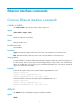
Ethernet interface commands Common Ethernet interface commands combo enable Use combo enable to activate the copper or fiber combo port. Syntax combo enable { copper | fiber } Default The fiber combo port is activated. Views Ethernet interface view Predefined user roles network-admin Parameters copper: Activates the copper combo port. In this case, use twisted pairs to connect the port. fiber: Activates the fiber combo port. In this case, use optical fibers to connect the port.
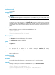
Views Ethernet interface view Predefined user roles network-admin Usage guidelines CAUTION: The default command might interrupt ongoing network services. Make sure you are fully aware of the impacts of this command when you use it in a live network. This command might fail to restore the default settings for some commands for reasons such as command dependencies and system restrictions.
display counters Use display counters to display interface traffic statistics. Syntax display counters { inbound | outbound } interface [ interface-type [ interface-number ] ] Views Any view Predefined user roles network-admin network-operator Parameters inbound: Displays inbound traffic statistics. outbound: Displays outbound traffic statistics. interface-type: Specifies an interface type. interface-number: Specifies an interface number.
Field Description Total (pkts) Total number of packets received or sent through the interface. Broadcast (pkts) Total number of broadcast packets received or sent through the interface. Multicast (pkts) Total number of multicast packets received or sent through the interface. Err (pkts) Total number of error packets received or sent through the interface.
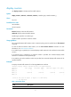
Examples # Display the inbound traffic rate statistics for all Ten-GigabitEthernet interfaces. display counters rate inbound interface ten-gigabitethernet Interface Total (pps) Broadcast (pps) Multicast (pps) XGE1/0/1 200 100 100 XGE1/0/2 300 200 100 XGE1/0/3 300 200 100 Overflow: More than 14 digits. --: Not supported. Table 2 Command output Field Description Interface Abbreviated interface name.
Usage guidelines If no interface type is specified, this command displays information about all interfaces. If an interface type is specified but no interface number is specified, this command displays information about all interfaces of that type. If both the interface type and interface number are specified, this command displays information about the specified interface. Examples # Display information about Layer 3 interface Ten-GigabitEthernet 1/0/1.
Table 3 Command output Field Description State of the interface: • Administratively DOWN—The Ethernet interface was shut down with the shutdown command. The interface is administratively down. Ten-GigabitEthernet1/0/1 current state • DOWN—The Ethernet interface is administratively up but physically down (possibly because no physical link is present or the link has failed). • UP—The Ethernet interface is both administratively and physically up.
UnTagged Vlan: 1 Port priority: 0 Last clearing of counters: Never Peak value of input: 0 bytes/sec, at 2012-10-10 10:06:20 Peak value of output: 0 bytes/sec, at 2012-10-10 10:06:20 Last 300 seconds input: Last 300 seconds output: Input (total): 0 packets/sec 0 bytes/sec -% 0 packets/sec 0 bytes/sec -% 0 packets, 0 bytes 0 unicasts, 0 broadcasts, 0 multicasts, 0 pauses Input (normal): 0 packets, - bytes 0 unicasts, 0 broadcasts, 0 multicasts, 0 pauses Input: 0 input errors, 0 runts, 0 giants, 0 thrott
Field Description Unknown-speed mode The speed of the interface is unknown because the speed negotiation fails or the interface is physically disconnected. half-duplex mode The interface is operating in half duplex mode. full-duplex mode The interface is operating in full duplex mode. unknown-duplex mode The duplex mode of the interface is unknown because the duplex mode negotiation fails or the interface is physically disconnected.
Field Description Peak value of output Peak rate of outbound traffic in Bps, and the time when the peak outbound traffic rate occurred. Last 300 seconds input: 0 packets/sec 0 bytes/sec 0% Last 300 seconds output: 0 packets/sec 0 bytes/sec 0% Input(total): 0 packets, 0 bytes 0 unicasts, 0 broadcasts, 0 multicasts, 0 pauses Average rate of inbound and outbound traffic in the last 300 seconds, in pps and Bps, and the ratio of the actual rate to the maximum interface rate.
Field Description Total number of illegal inbound packets: • Fragment frames—CRC error frames shorter than 64 bytes. The length can be an integral or non-integral value. • Jabber frames—CRC error frames greater than the maximum aborts frame length supported on the Ethernet interface (with an integral or non-integral length). For an Ethernet interface that does not permit jumbo frames, jabber frames refer to CRC error frames greater than 1518 bytes (without VLAN tags) or 1522 bytes (with VLAN tags).
Field Description collisions Number of frames that the interface stopped transmitting because Ethernet collisions were detected during transmission. late collisions Number of frames that the interface deferred to transmit after transmitting their first 512 bits because of detected collisions. lost carrier Number of carrier losses during transmission. This counter increases by one when a carrier is lost, and applies to serial WAN interfaces.
Link: ADM - administratively down; Stby - standby Protocol: (s) - spoofing Interface Link Protocol Main IP Description XGE1/0/2 UP UP 10.1.1.2 Link to CoreRouter Loop0 UP UP(s) 2.2.2.9 NULL0 UP UP(s) -- Vlan1 UP DOWN -- Vlan999 UP UP 192.168.1.
Field Description Physical link state of the interface: • UP—The link is up. Link • DOWN—The link is physically down. • ADM—The link has been administratively shut down. To recover its physical state, run the undo shutdown command. • Stby—The interface is a standby interface. Protocol connection state of the interface: • UP. Protocol • DOWN. • UP(s)—The link of the interface is an on-demand link or not present at all. Description Interface description configured by using the description command.
Field Description Causes for the physical state of an interface to be DOWN. • Not connected—No physical connection exists (possibly because the Cause network cable is disconnected or faulty). • Administratively DOWN—The port was shut down with the shutdown command. To restore the physical state of the interface, use the undo shutdown command. display packet-drop Use display packet-drop to display information about packets dropped on an interface or multiple interfaces.
Table 6 Command output Field Description Packets dropped due to full GBP or insufficient bandwidth Packets that are dropped because the buffer is used up or the bandwidth is insufficient. Packets dropped due to Fast Filter Process (FFP) Packets that are filtered out. Packets dropped due to STP non-forwarding state Packets that are dropped because STP is in the non-forwarding state. duplex Use duplex to set the duplex mode for an Ethernet interface.
flow-control Use flow-control to enable TxRx mode generic flow control on an Ethernet interface. Use undo flow-control to disable generic flow control on the Ethernet interface. Syntax flow-control undo flow-control Default Generic flow control is disabled on an Ethernet interface. Views Ethernet interface view Predefined user roles network-admin Usage guidelines To implement flow control on a link, enable the generic flow control function at both ends of the link.
Usage guidelines With the flow-control receive enable command configured, an interface can receive, but not send, flow control frames. When the interface receives a flow control frame from its peer, it suspends sending packets to the peer. When traffic congestion occurs on the interface, it cannot send flow control frames to the peer. To handle unidirectional traffic congestion on a link, configure the flow-control receive enable command at one end, and the flow-control command at the other.
Syntax interface interface-type interface-number Views System view Predefined user roles network-admin Parameters interface-type: Specifies an interface type. interface-number: Specifies an interface number. Examples # Enter Ten-GigabitEthernet 1/0/1 interface view. system-view [Sysname] interface ten-gigabitethernet 1/0/1 [Sysname-Ten-GigabitEthernet1/0/1] jumboframe enable Use jumboframe enable to allow jumbo frames within the specified length to pass through.
link-delay Use link-delay to set the physical state change suppression interval on an Ethernet interface. Use undo link-delay to restore the default. Syntax link-delay delay-time [ mode { up | updown } ] undo link-delay Default Each time the physical link of an interface goes up or comes down, the interface immediately reports the change to the CPU.
loopback Use loopback to perform a loopback test on an Ethernet interface. Use undo loopback to cancel a loopback test on an Ethernet interface. Syntax loopback { external | internal } undo loopback Views Ethernet interface view Predefined user roles network-admin Parameters external: Performs an external loopback test on the Ethernet interface. internal: Performs an internal loopback test on the Ethernet interface.
Views Ethernet interface view Predefined user roles network-admin Parameters bridge: Specifies the Layer 2 mode. route: Specifies the Layer 3 mode. Usage guidelines On the switch, Ethernet interfaces can operate either as Layer 2 Ethernet interfaces (in bridge mode) or Layer 3 Ethernet interfaces (in route mode). After you change the link mode of an Ethernet interface, all the settings of the Ethernet interface are restored to their defaults under the new link mode.
To use the PFC feature on a link, make sure it is enabled on both ends of the link. An interface processes PFC pause frames only when PFC is enabled on it. The state of the PFC function is co-determined by the PFC configurations on the local port and on the peer. In Table 7, the first line lists the PFC configuration on the local port, the first column lists the PFC configuration on the peer, and enabled and disabled are the two possible negotiation results.
Usage guidelines PFC performs flow control based on 802.1p priorities. With PFC enabled, an interface requires its peer to suspend sending packets with certain 802.1p priorities when congestion occurs. By decreasing the transmission rate, PFC helps avoid packet loss. You can enable PFC for certain 802.1p priorities at the two ends of a link. When network congestion occurs, the local switch checks the PFC status for the 802.1p priority carried in each arriving packet. • If PFC is enabled for the 802.
the range specified by the dot1p-list argument, the port preferentially sends the packet. For more information about the 802.1p-local priority mapping table, see ACL and QoS Configuration Guide. If you configure the flow control or flow-control receive enable command on a PFC-enabled port, the PFC configuration takes effect, and the configuration of the flow control or flow-control receive enable command is ignored. The latter takes effect on the port only when PFC is disabled on it.
• display counters interface • display counters rate interface reset packet-drop interface Use reset packet-drop interface to clear the dropped packet statistics on an interface or multiple interfaces. Syntax reset packet-drop interface [ interface-type [ interface-number ] ] Views User view Predefined user roles network-admin Parameters interface-type: Specify an interface type.
Usage guidelines You might need to shut down and then bring up an Ethernet interface to make some interface configurations take effect. Examples # Shut down and then bring up Ten-GigabitEthernet 1/0/1. system-view [Sysname] interface ten-gigabitethernet 1/0/1 [Sysname-Ten-GigabitEthernet1/0/1] shutdown [Sysname-Ten-GigabitEthernet1/0/1] undo shutdown speed Use speed to set the speed of an Ethernet interface. Use undo speed to restore the default.
GE copper ports do not support the 10000 or 40000 keyword. Examples # Configure Ten-GigabitEthernet 1/0/1 to autonegotiate the speed. system-view [Sysname] interface ten-gigabitethernet 1/0/1 [Sysname-Ten-GigabitEthernet1/0/1] speed auto using fortygige Use using fortygige to combine four 10-GE interfaces that are split from a 40-GE interface into a 40-GE interface. Use undo using fortygige to cancel the configuration.
Use undo using tengige to cancel the configuration. Syntax using tengige undo using tengige Default A 40-GE interface is used as a single interface, and is not automatically split. Views 40-GE interface view Predefined user roles network-admin Usage guidelines You can use a 40-GE interface as a single interface. You can also split a 40-GE interface into four 10-GE interfaces to improve the port density, reduce the cost, and improve the network flexibility.
Views Layer 2 Ethernet interface view Predefined user roles network-admin Parameters ratio: Sets the broadcast suppression threshold as a percentage of the maximum interface rate. This argument is in the range of 0 to 100. The smaller the percentage, the less broadcast traffic is allowed to pass through. pps max-pps: Specifies the maximum number of broadcast packets that the interface can forward per second. The max-pps argument (in pps) is in the range of 1 to 1.4881 × the maximum interface rate.
display storm-constrain Use display storm-constrain to display storm control settings and statistics. Syntax display storm-constrain [ broadcast | multicast | unicast ] [ interface interface-type interface-number ] Views Any view Predefined user roles network-admin network-operator Parameters broadcast: Displays broadcast storm control settings and statistics. multicast: Displays multicast storm control settings and statistics. unicast: Displays unknown unicast storm control settings and statistics.
Field Description Storm control threshold unit: Unit • pps. • kbps. • percentage. CtrlMode Protective action (block or shutdown) taken on the port when the upper threshold is reached. N/A indicates that no protective action is configured. Packet forwarding status: Status • forwarding—The port is forwarding traffic correctly. • shutdown—The port has been shut down. • block—The port drops the type of traffic.
mdi: Specifies that pins 1 and 2 are transmit pins and pins 3 and 6 are receive pins. mdix: Specifies that pins 1 and 2 are receive pins and pins 3 and 6 are transmit pins. Examples # Set Ten-GigabitEthernet 1/0/1 to operate in MDI mode. system-view [Sysname] interface ten-gigabitethernet 1/0/1 [Sysname-Ten-GigabitEthernet1/0/1] mdix-mode mdi multicast-suppression Use multicast-suppression to enable multicast storm suppression and set the multicast storm suppression threshold.
When you configure the multicast suppression threshold in kbps, the switch automatically uses a multiple of 64 as the threshold. If you configure a value less than 64, the switch sets the threshold to 64 kbps. If you configure a value greater than 64, the switch sets the threshold to a multiple of 64 which is greater than the configured value and is nearest to the value than other multiples. Examples # Set the multicast storm suppression threshold to 10000 kbps on Ten-GigabitEthernet 1/0/1.
upperlimit: Sets the upper threshold, in pps, kbps, or percentage. lowerlimit: Sets the lower threshold, in pps, kbps, or percentage. Usage guidelines After you configure this command, the device collects the statistics of a particular type of traffic at the specified interval, which can be configured by using the storm-constrain interval command.
Default No action is taken on an Ethernet interface when a type of traffic exceeds the upper storm control threshold. Views Layer 2 Ethernet interface view Predefined user roles network-admin Parameters block: Blocks this type of traffic, while forwarding other types of traffic. Even though the interface does not forward the blocked traffic, it still counts the traffic. When the blocked traffic is detected dropping below the lower threshold, the port begins to forward the traffic.
system-view [Sysname] interface ten-gigabitethernet 1/0/1 [Sysname-Ten-GigabitEthernet1/0/1] storm-constrain enable log storm-constrain enable trap Use storm-constrain enable trap to enable an Ethernet interface to send storm control threshold event traps. Use undo storm-constrain enable trap to disable trap sending.
Usage guidelines The interval set by the storm-constrain interval command is specific to storm control. To set the statistics polling interval of an interface, use the flow-interval command. For network stability, use the default or a higher polling interval. Examples # Set the traffic statistics polling interval of the storm control module to 60 seconds.
Both the storm-constrain and unicast-suppression can suppress unicast storm on a port. The storm-constrain command uses software to suppress unicast traffic, and it affects the device performance to a certain extent. The unicast-suppression command use the chip to physically suppress unicast traffic, and it has less influence on the device performance than the storm-constrain command. Do not configure the storm constrain command and the unicast-suppression command at the same time.
system-view [Sysname] interface ten-gigabitethernet 1/0/1 [Sysname-Ten-GigabitEthernet1/0/1] virtual-cable-test Cable status: normal, 38 metre(s) Pair Impedance mismatch: yes Pair skew: 38 ns Pair swap: Pair polarity: swap Insertion loss: 12 db Return loss: 11 db Near-end crosstalk: 13 db Table 10 Command output Field Description Cable status: • Normal—The cable is in good condition. Cable status • Abnormal—The cable is abnormal. • Abnormal (open)—An open circuit is detected.
Usage guidelines Set an appropriate MTU to avoid fragmentation. The MTU for the interface applies to only packets that are sent to the CPU for forwarding by software, for example, the packets that are sourced from or destined to the interface. As the MTU size decreases, the number of fragments grows. When you set the MTU for an interface, you should consider QoS queue lengths (for example, the default FIFO queue length is 75) to prevent a too small MTU from causing packet drops in QoS queuing.
Loopback and null interface commands default Use default to restore the default settings for a loopback or null interface. Syntax default Views Loopback interface view, null interface view Predefined user roles network-admin Usage guidelines CAUTION: The default command might interrupt ongoing network services. Make sure you are fully aware of the impacts of this command before using it on a live network.
Predefined user roles network-admin Parameters text: Specifies an interface description, a string of 1 to 80 characters. Usage guidelines Configure a description for an interface for easy identification and management purposes. You can use the display interface command to view the configured description. Examples # Set the description to for RouterID for interface loopback 1.
Examples # Display detailed information about interface loopback 0.
Field Description Average output rate over the last 300 seconds (displayed when the interface supports traffic statistics collection): Last 300 seconds output: 0 bytes/sec, 0 bits/sec, 0 packets/sec • packets/sec—Average number of packets sent per second. • bytes/sec—Average number of bytes sent per second. • bits/sec—Average number of bits sent per second.
Field Description Physical link state of the interface: • UP—The link is up. • DOWN—The link is physically down. Link • ADM—The link has been administratively shut down. To recover its physical state, run the undo shutdown command. • Stby—The interface is a standby interface. Protocol connection state of the interface: • UP. Protocol • DOWN. • UP(s)—The link of the interface is an on-demand link or not present at all. Description Interface description configured by using the description command.
If the null keyword is not specified, the command displays information about all interfaces of the device. If the null keyword is specified but the 0 keyword is not specified, the command displays information about interface Null 0, because the device has only one null interface Null 0. Examples # Display detailed information about interface Null 0.
Default No loopback interface exists. Views System view Predefined user roles network-admin Parameters interface-number: Specifies a loopback interface by its number in the range of 0 to 1023. Usage guidelines The physical layer state and link layer protocols of a loopback interface are always up unless the loopback interface is manually shut down.
reset counters interface loopback Use reset counters interface loopback to clear the statistics on the specified or all loopback interfaces. Syntax reset counters interface [ loopback [ interface-number ] ] Views User view Predefined user roles network-admin Parameters interface-number: Specifies a loopback interface by its number, which can be the number of any existing loopback interface. If you do not specify the interface-number argument, the command clears the statistics on all loopback interfaces.
Examples # Clear the statistics on interface Null 0. reset counters interface null 0 Related commands display interface null shutdown Use shutdown to shut down a loopback interface. Use undo shutdown to bring up a loopback interface. Syntax shutdown undo shutdown Default A loopback interface is up.
Bulk interface configuration commands interface range Use interface range to create an interface range and enter the interface range view. Syntax interface range interface-list Views System view Predefined user roles network-admin Parameters interface-list: Specifies an interface list in the format of interface-list = { interface-type interface-number [ to interface-type interface-number ] }&<1-5>. The interface-type interface-number argument specifies an interface by its type and number.
Examples # Shut down interfaces Ten-GigabitEthernet 1/0/1 through Ten-GigabitEthernet 1/0/24, VLAN interface 2. system-view [Sysname] interface range ten-gigabitethernet 1/0/1 to ten-gigabitethernet 1/0/24 vlan-interafce 2 [Sysname-if-range] shutdown interface range name Use interface range name name interface interface-list to create an interface range, configure a name for the interface range, and enter the interface range view.
To view the member interfaces of an interface range, use the display current-configuration | include "interface range" command. To bulk configure interfaces, follow these guidelines: • If you cannot enter the view of an interface by using the interface interface-type interface-number command, do not configure the interface as the first interface in the interface range. • Do not assign an aggregate interface and any of its member interfaces to an interface range at the same time.
MAC address table commands The MAC address table contains only Layer 2 Ethernet interfaces and Layer 2 aggregate interfaces. This document covers the configuration of unicast MAC address entries, including static, dynamic, blackhole, and multiport unicast MAC address entries. For more information about configuring static multicast MAC address entries, see IP Multicast Configuration Guide. For more information about MAC address table configuration in VPLS, see MPLS Configuration Guide.
display mac-address vlan 100 MAC Address VLAN ID State Port/NickName 0001-0101-0101 100 Multiport XGE1/0/1 Aging N XGE1/0/2 0033-0033-0033 100 Blackhole N/A N 0000-0000-0002 100 Static XGE1/0/3 N 00e0-fc00-5829 100 Learned XGE1/0/4 Y # Display the total number of MAC address entries. display mac-address count 1 mac address(es) found.
Predefined user roles network-admin network-operator Examples # Display the aging timer for dynamic MAC address entries. display mac-address aging-time MAC address aging time: 300s. Related commands mac-address timer display mac-address mac-learning Use display mac-address mac-learning to verify whether MAC address learning has been enabled globally or on an interface.
Field Description Learning Status • Enabled. MAC address learning status of an interface: • Disabled. Related commands mac-address mac-learning enable display mac-address statistics Use display mac-address statistics to display MAC address table statistics.
Field Description Static Unicast Address (User-defined) Count Number of static unicast MAC address entries added by users. Static Unicast Address (System-defined) Count Number of static unicast MAC address entries added by the system. Total Unicast MAC Addresses In Use Total number of unicast MAC address entries. Total Unicast MAC Addresses Available Maximum number of unicast MAC address entries allowed.
dynamically learned entries, using manually configured static MAC address entries prevents hackers from using forged MAC addresses to steal data. The MAC address entries configuration cannot survive a reboot unless you save it. The dynamic MAC address entries, however, are lost upon reboot regardless of whether you save the configuration. Examples # Add a static entry for MAC address 000f-e201-0101 on interface Ten-GigabitEthernet 1/0/1 that belongs to VLAN 2.
Parameters blackhole: Specifies blackhole MAC address entries. The packets whose source or destination MAC addresses match blackhole MAC address entries are dropped. mac-address: Specifies a MAC address in the format of H-H-H. When entering a MAC address, you can omit the leading zeros in each H section. For example, enter f-e2-1 for 000f-00e2-0001. vlan vlan-id: Specifies an existing VLAN to which the interface belongs. The value range for the vlan-id argument is 1 to 4094.
Use undo mac-address mac-learning enable to disable MAC address learning. Depending on the view that you entered, you can disable it globally, on an interface, or on a VLAN. Syntax mac-address mac-learning enable undo mac-address mac-learning enable Default MAC address learning is enabled.
system-view [Sysname] interface bridge-aggregation 1 [Sysname-Bridge-Aggregation1] undo mac-address mac-learning enable # Disable MAC address learning on interface S-Channel 1/0/1:10. system-view [Sysname] interface s-channel 1/0/1:10 [Sysname-S-Channel1/0/1:10] undo mac-address mac-learning enable Related commands display mac-address mac-learning mac-address mac-learning priority Use mac-address mac-learning priority to assign MAC learning priority to an interface.
[Sysname] interface bridge-aggregation 1 [Sysname-Bridge-Aggregation1] mac-address mac-learning priority high # Assign high MAC learning priority to interface S-Channel 1/0/1:10. system-view [Sysname] interface s-channel 1/0/1:10 [Sysname-S-Channel1/0/1:10] mac-address mac-learning priority high mac-address mac-roaming enable Use mac-address mac-roaming enable to enable MAC address synchronization. Use undo mac-address mac-roaming enable to restore the default.
Syntax mac-address max-mac-count { count | enable-forwarding } undo mac-address max-mac-count [ enable-forwarding ] Default The maximum number of MAC addresses that can be learned on an interface is not configured. When the upper limit is reached, the received frames are forwarded. Views Layer 2 Ethernet interface view Predefined user roles network-admin Parameters count: Sets the maximum number of MAC addresses that can be learned on an interface. The value range is 0 to 4096.
Views Layer 2 Ethernet interface view, Layer 2 aggregate interface view Predefined user roles network-admin Parameters mac-address: Specifies a unicast MAC address in H-H-H format, excluding multicast and all-zero MAC addresses. When entering a MAC address, you can omit the leading zeros in each H section. For example, enter f-e2-1 for 000f-00e2-0001. vlan vlan-id: Specifies an existing VLAN to which the interface belongs. The value range for the vlan-id argument is 1 to 4094.
Predefined user roles network-admin Parameters multiport: Specifies a multiport unicast MAC address entry. mac-address: Specifies a unicast MAC address in H-H-H format, excluding multicast and all-zero MAC addresses. When entering a MAC address, you can omit the leading zeros in each H section. For example, enter f-e2-1 for 000f-00e2-0001. interface interface-list: Specifies interfaces in the format of { { interface-type interface-number } [ to { interface-type interface-number } ] } &<1-4>.
Predefined user roles network-admin Parameters aging seconds: Sets an aging timer for dynamic MAC address entries, in the range of 10 to 1000000 seconds. no-aging: Sets dynamic MAC address entries not to age. Usage guidelines After the network topology changes, the dynamic MAC address entries are not updated in a timely manner. As a result, the device cannot learn new MAC addresses and fails to forward the user traffic correctly.
MAC Information commands mac-address information enable (interface view) Use mac-address information enable to enable MAC Information on an interface. Use undo mac-address information enable to disable MAC Information on an interface. Syntax mac-address information enable { added | deleted } undo mac-address information enable { added | deleted } Default MAC Information is disabled on an interface.
mac-address information enable (system view) Use mac-address information enable to enable MAC Information globally. Use undo mac-address information enable to disable MAC Information globally. Syntax mac-address information enable undo mac-address information enable Default MAC Information is disabled globally. Views System view Predefined user roles network-admin Usage guidelines Before you enable MAC Information on an interface, enable MAC Information globally.
Usage guidelines To prevent syslog messages or SNMP notifications from being sent too frequently, set the MAC change sending interval to a larger value. Examples # Set the MAC change sending interval to 200 seconds. system-view [Sysname] mac-address information interval 200 mac-address information mode Use mac-address information mode to set the MAC Information mode (to use syslog messages or SNMP notifications) to send MAC address changes.
Views System view Predefined user roles network-admin Parameters value: Specifies the MAC Information queue length in the range of 0 to 1000. Usage guidelines If the MAC Information queue length is 0, the device sends a syslog message or SNMP notification immediately after learning or deleting a MAC address.
Ethernet link aggregation commands default Use default to restore the default settings for an aggregate interface. Syntax default Views Layer 2 aggregate interface view Predefined user roles network-admin Usage guidelines CAUTION: The default command might interrupt ongoing network services. Make sure you are fully aware of the impacts of this command when you perform it on a live network.
Views Layer 2 aggregate interface view Predefined user roles network-admin Parameters text: Specifies the interface description, a string of 1 to 80 characters. Examples # Set the description of Layer 2 aggregate interface Bridge-Aggregation 1 to connect to the lab. system-view [Sysname] interface bridge-aggregation 1 [Sysname-Bridge-Aggregation1] description connect to the lab display interface Use display interface to display aggregate interface information.
Bridge-Aggregation1 current state: UP IP Packet Frame Type: PKTFMT_ETHNT_2, Hardware Address: 00e0-fc01-5834 Description: Bridge-Aggregation1 Interface 30Gbps-speed mode, full-duplex mode Link speed type is autonegotiation, link duplex type is autonegotiation PVID: 1 Port link-type: trunk VLAN Passing: 1(default vlan), 10,20 VLAN permitted: 1(default vlan), 10,20 Trunk port encapsulation: IEEE 802.
Table 16 Command output Field Description Layer 2 aggregate interface status: • DOWN (Administratively down)—The interface is administratively shut down with the shutdown command. • DOWN—The interface is administratively up but Bridge-Aggregation1 current state physically down (possibly because no physical link is present or the link is faulty). • UP—The Ethernet interface is both administratively and physically up. IPv4 packet frame format.
Field Description Time when the reset counters interface command was last used to clear the interface statistics. Last clearing of counters Never indicates the reset counters interface command has never been used on the interface since the device's startup. Last 300 seconds input/output rate Average input/output rate over the last 300 seconds. Input/Output (total) Statistics of all packets received/sent on the interface.
Usage guidelines You can use the lacp system-priority command to change the LACP priority of the local system. You specify the LACP priority value in decimal format in the lacp system-priority command, but it is displayed as a hexadecimal value by the display lacp system-id command. Examples # Display the local system ID.
Examples # Display the global link-aggregation load sharing criteria. display link-aggregation load-sharing mode Link-Aggregation Load-Sharing Mode: Layer 2 traffic: destination-mac address source-mac address Layer 3 traffic: destination-ip address source-ip address # Display the link-aggregation load sharing criteria of the aggregation group that corresponds to aggregate interface Bridge-Aggregation 10.
network-operator Parameters interface-list: Specifies a list of link aggregation member ports, in the format interface-type interface-number [ to interface-type interface-number ], where interface-type interface-number specifies an interface by its type and number. Usage guidelines For a member port in a static aggregation group, which is unaware of information about the peer group, this command displays the port number, port priority, and operational key of the local end only.
Table 19 Command output Field Description LACP state flags. This field is one byte long, represented by ABCDEFGH from the least significant bit to the most significant bit. The letter is present when its bit is 1 and absent when its bit is 0. • A—Indicates whether LACP is enabled. 1 indicates enabled, and 0 indicates disabled. • B—Indicates the LACP short or long timeout. 1 indicates short timeout, and 0 indicates long timeout.
Usage guidelines Information about the remote system for a static link aggregation group is displayed as none, because static link aggregation groups are unaware of information about the peer groups. Examples # Display the summary information for all aggregation groups.
Syntax display link-aggregation verbose [ bridge-aggregation [ interface-number ] ] Views Any view Predefined user roles network-admin network-operator Parameters bridge-aggregation: Displays detailed information about the Layer 2 aggregation groups that correspond to Layer 2 aggregate interfaces. interface-number: Specifies an existing aggregate interface by its number. Usage guidelines If you specify only bridge-aggregation, this command displays information about all Layer 2 aggregation groups.
# Display detailed information about the aggregation group that corresponds to Layer 2 aggregate interface Bridge-Aggregation 20, which is a static aggregation group.
Field Description Mode of the aggregation group: Aggregation Mode • Static for static aggregation. • Dynamic for dynamic aggregation. System ID Local system ID, comprising the system LACP priority and the system MAC address. Information about the local end: • Port—Port type and number. • Status—Selected or Unselected state of the port. • Priority—Port priority. Local • Oper-Key—Operational key. • Flag—LACP state flag.
Usage guidelines When you create a Layer 2 aggregate interface, the system automatically creates a Layer 2 aggregation group with the same number, which operates in static aggregation mode by default. If you remove the Layer 2 aggregate interface, you also remove the Layer 2 aggregation group, and any member ports leave the aggregation group. Examples # Create Layer 2 aggregate interface Bridge-Aggregation 1, and enter its view.
Default The system LACP priority is 32768. Views System view Predefined user roles network-admin Parameters system-priority: Specifies the system LACP priority in the range of 0 to 65535. The smaller the value, the higher the system LACP priority. Examples # Set the system LACP priority to 64.
Usage guidelines This command takes effect on only known unicast packets and can change the global load sharing criteria for known unicast packets. Broadcast packets, multicast packets, and unknown unicast packets always use the default global load sharing criteria. The load sharing criteria that you configure overwrite the previous criteria. If unsupported load sharing criteria are configured, an error prompt appears.
Usage guidelines With this feature, when you restart a card that contains Selected ports, traffic can be redirected to other cards. Zero packet loss is guaranteed for known unicast traffic, but not for unknown unicast traffic. (In standalone mode.) With this feature, when you restart an IRF member device or its card that contains Selected ports, traffic can be redirected to other IRF member devices or other cards. Zero packet loss is guaranteed for known unicast traffic, but not for unknown unicast traffic.
flexible: Performs load sharing in link aggregation groups flexibly based on packet types (Layer 2, IPv4, IPv6, or MPLS for example). Usage guidelines This command takes effect on only unicast packets and can change the load sharing criteria for known unicast packets. Broadcast packets, multicast packets, and unknown unicast packets always use the default load sharing criteria. The load sharing criteria that you configure overwrites the previous criteria.
Description Use link-aggregation load-sharing mode local-first to enable local-first load sharing for link aggregation. Use undo link-aggregation load-sharing mode local-first to disable local-first load sharing for link aggregation. After you disable local-first load sharing for link aggregation, the packets to be forwarded out of an aggregate interface will be load-shared among all Selected ports of the aggregate interface on all IRF member devices.
undo link-aggregation port-priority Default The port priority of an interface is 32768. Views Layer 2 Ethernet interface view Predefined user roles network-admin Parameters port-priority: Specifies the port priority in the range of 0 to 65535. The smaller the value, the higher the port priority. Examples # Set the port priority of Layer 2 Ethernet interface Ten-GigabitEthernet 1/0/1 to 64.
The maximum numbers of Selected ports allowed in the aggregation groups of the local and peer ends must be consistent. After you manually configure the maximum number of Selected ports in an aggregation group, the maximum number of Selected ports allowed in the aggregation group is limited by both the configured number and hardware capabilities, that is, the lower value of the two upper limits.
Examples # Configure the minimum number of Selected ports as 3 in the aggregation group that corresponds to Layer 2 aggregate interface Bridge-Aggregation 1. system-view [Sysname] interface bridge-aggregation 1 [Sysname-Bridge-Aggregation1] link-aggregation selected-port minimum 3 Related commands link-aggregation selected-port maximum port link-aggregation group Use port link-aggregation group to assign the Ethernet interface to the specified aggregation group.
Predefined user roles network-admin Parameters bridge-aggregation: Clears statistics for Layer 2 aggregate interfaces. interface-number: Specifies an aggregate interface number. Usage guidelines Before collecting statistics for a Layer 2 aggregate interface within a specific period, clear its existing statistics. If no option is specified, the command clears the statistics for all interfaces in the system.
shutdown Use shutdown to shut down the aggregate interface. Use undo shutdown to bring up the aggregate interface. Syntax shutdown undo shutdown Default Aggregate interfaces are up. Views Layer 2 aggregate interface view Predefined user roles network-admin Examples # Bring up Layer 2 aggregate interface Bridge-Aggregation 1.
Port isolation commands display port-isolate group Use display port-isolate group to display port isolation group information. Syntax display port-isolate group [ group-number ] Views Any view Predefined user roles network-admin network-operator Parameters group-number: Specifies an isolation group by its number in the range of 1 to 8. Examples # Display all isolation groups.
port-isolate enable Use port-isolate enable to assign a port to an isolation group. Use undo port-isolate enable to remove a port from an isolation group. Syntax port-isolate enable group group-number undo port-isolate enable Default No ports are assigned to an isolation group. Views Layer 2 Ethernet interface view, Layer 2 aggregate interface view Predefined user roles network-admin Parameters group group-number: Specifies an isolation group by its number in the range of 1 to 8.
Syntax port-isolate group group-number undo port-isolate group { group-number | all } Default No isolation group exists. Views System view Predefined user roles network-admin Parameters group-number: Specifies an isolation group by its number in the range of 1 to 8. all: Deletes all isolation groups. Examples # Create isolation group 2.
Spanning tree commands active region-configuration Use active region-configuration to activate your MST region configuration. Syntax active region-configuration Views MST region view Predefined user roles network-admin Usage guidelines When you configure MST region parameters, MSTP launches a new spanning tree calculation process that might cause network topology instability. This is most likely to occur when you configure the VLAN-to-instance mapping table.
Views MST region view Predefined user roles network-admin Usage guidelines Two or more spanning tree devices belong to the same MST region only if they are configured with the same format selector (0 by default and not configurable), MST region name, and MST region revision level, have the same VLAN-to-instance mapping entries in the MST region, and are connected through a physical link. HP recommends that you use this command to determine whether the MST region configurations to be activated are correct.
display stp Use display stp to display the spanning tree status and statistics information. Based on the information, you can analyze and maintain the network topology or determine whether the spanning tree is working correctly.
• If you do not specify any MSTI or port, this command displays the spanning tree information of all MSTIs on all ports. The displayed information is sorted by MSTI ID and by port name in each MSTI. • If you specify an MSTI but not a port, this command displays the spanning tree information on all ports in that MSTI. The displayed information is sorted by port name. • If you specify some ports but not an MSTI, this command displays the spanning tree information of all MSTIs on the specified ports.
-------[CIST Global Info][Mode MSTP]------Bridge ID : 32768.000f-e200-2200 Bridge times : Hello 2s MaxAge 20s FwdDelay 15s MaxHops 20 Root ID/ERPC : 0.00e0-fc0e-6554, 200200 RegRoot ID/IRPC : 32768.000f-e200-2200, 0 RootPort ID : 128.
CIST Bridge-Prio. : 32768 MAC address : 000f-e200-8048 Max age(s) : 20 Forward delay(s) : 15 Hello time(s) : 2 Max hops : 20 Table 25 Command output Field Description Bridge ID Bridge ID, which comprises the device's priority in the MSTI and its MAC address. For example, in output "32768.000f-e200-2200," the value preceding the dot is the device's priority in the MSTI, and the value following the dot is the device's MAC address.
Field Desg.bridge/port Description Designated bridge ID and port ID of the port. The port ID displayed is insignificant for a port which does not support port priority. The port is an edge port or non-edge port. Port edged • Config—Configured value. • Active—Actual value. The port is connected to a point-to-point link or not. Point-to-Point • Config—Configured value. • Active—Actual value. Transmit limit Maximum number of packets sent within each hello time.
Field Description Protocol Std. Spanning tree protocol standard. Version Spanning tree protocol version. CIST Bridge-Prio. Device's priority in the CIST. Max age(s) Aging timer (in seconds) for BPDUs. Forward delay(s) Port state transition delay (in seconds). Hello time(s) Interval (in seconds) for the root bridge to send BPDUs. Max hops Maximum hops in the MSTI.
display stp bpdu-statistics Use display stp bpdu-statistics to display the BPDU statistics on ports. Syntax display stp bpdu-statistics [ interface interface-type interface-number [ instance instance-list ] ] Views Any view Predefined user roles network-admin network-operator Parameters interface interface-type interface-number: Displays the BPDU statistics on the specified port, where interface-type interface-number represents the port type and number.
TCN sent 0 TCN received 0 TCA sent 0 TCA received 2 Config sent 0 Config received 0 RST sent 0 RST received 0 MST sent 4 10:33:11 01/13/2011 MST received 151 10:37:43 01/13/2011 Count Last Updated 10:33:12 01/13/2011 Instance 0: Type --------------------------- ---------- ----------------Timeout BPDUs 0 MAX-hoped BPDUs 0 TC detected 1 10:32:40 01/13/2011 TC sent 3 10:33:11 01/13/2011 TC received 0 Table 27 Command output Field Description Port Port name.
Field Description TC received TC BPDUs received. display stp down-port Use display stp down-port to display information about ports that were shut down by spanning tree protection functions. Syntax display stp down-port Views Any view Predefined user roles network-admin network-operator Examples # Display information about ports that were shut down by spanning tree protection functions.
Parameters instance instance-list: Displays the historical port role calculation information for the MSTIs that are specified by an instance list, in the format of instance-list = { instance-id [ to instance-id ] }&<1-10>, where &<1-10> indicates that you can specify up to 10 instances or instance ranges. The value range for the instance-id argument is 0 to 4094, and the value 0 represents the CIST. slot slot-number: Displays the historical port role calculation information on the specified card.
Port Ten-GigabitEthernet1/0/2 Role change : ALTER->ROOT Time : 2009/02/08 00:22:56 Port priority : 0.00e0-fc01-6510 0 0.00e0-fc01-6510 128.2 128.153 Table 29 Command output Field Description Port Port name. Role change Role change of the port ("Aged" means that the change was caused by expiration of the received configuration BPDU). Time Time of port role calculation. Port priority Port priority.
Field Description Revision level Revision level of the MST region. The default value is 0, and the level can be configured by using the revision-level command. VLANs Mapped VLANs mapped to the MSTI. Related commands • instance • region-name • revision-level • vlan-mapping modulo display stp root Use display stp root to display the root bridge information of all MSTIs.
display stp [ instance instance-list ] tc [ slot slot-number ] In IRF mode: display stp [ instance instance-list ] tc [ chassis chassis-number slot slot-number ] Views Any view Predefined user roles network-admin network-operator Parameters instance instance-list: Displays the statistics of TC/TCN BPDUs received and sent by all ports in the MSTIs that are specified by an instance list, in the format of instance-list = { instance-id [ to instance-id ] }&<1-10>, where &<1-10> indicates that you can specify
--------- STP chassis 1 slot 1 TC or TCN count -------MSTID Port Receive Send 0 Ten-GigabitEthernet1/0/1 6 4 0 Ten-GigabitEthernet1/0/2 0 2 Table 32 Command output Field Description Port Port name. Receive Number of TC/TCN BPDUs received on each port. Send Number of TC/TCN BPDUs sent by each port. instance Use instance to map a list of VLANs to the specified MSTI. Use undo instance to remap the specified VLAN or all VLANs to the CIST (MSTI 0).
operations might cause loops or traffic interruption because the VLAN-to-instance mappings are inconsistent with those on the neighboring devices. Examples # Map VLAN 2 to MSTI 1. system-view [Sysname] stp region-configuration [Sysname-mst-region] instance 1 vlan 2 Related commands • active region-configuration • check region-configuration • display stp region-configuration region-name Use region-name to configure the MST region name.
• display stp region-configuration • instance • revision-level • vlan-mapping modulo reset stp Use reset stp to clear the MSTP statistics information. The MSTP statistics information includes the numbers of TCN BPDUs, configuration BPDUs, RST BPDUs, and MST BPDUs that are sent and received through the specified ports.
Parameters level: Specifies an MSTP revision level in the range of 0 to 65535. Usage guidelines The MSTP revision level, the MST region name, and the VLAN-to-instance mapping table of a device determine the device's MST region. When the MST region name and VLAN-to-instance mapping table are both the same for two MST regions, they can still be differentiated by their MSTP revision levels. After configuring this command, run the active region-configuration command to activate the configured MST region level.
stp bridge-diameter Use stp bridge-diameter to specify the network diameter, which is the maximum possible number of stations between any two terminal devices on the switched network. Use undo stp bridge-diameter to restore the default. Syntax stp bridge-diameter diameter undo stp bridge-diameter Default The network diameter of the switched network is 7. Views System view Predefined user roles network-admin Parameters diameter: Specifies the switched network diameter in the range of 2 to 7.
Default A port automatically recognizes the formats of received MSTP packets and determines the formats of MSTP packets to be sent based on the recognized formats. Views Layer 2 Ethernet interface view, Layer 2 aggregate interface view Predefined user roles network-admin Parameters auto: Configures the ports to recognize the MSTP BPDU format automatically and determine the format of MSTP BPDUs to send. dot1s: Configures the ports to receive and send only standard-format (802.1s-compliant) MSTP BPDUs.
When the setting is configured in Layer 2 Ethernet interface view, it takes effect only on that interface. When the setting is configured in Layer 2 aggregate interface view, it takes effect only on the aggregate interface. When the setting is configured on a member port in an aggregation group, it takes effect only after the port leaves the aggregation group. Examples # Enable digest snooping on Ten-GigabitEthernet 1/0/1 and then globally.
• When the private standard is selected for path cost calculation, the value range for the cost argument is 1 to 200000. Usage guidelines Path cost is an important factor in spanning tree calculation. Setting different path costs for a port in MSTIs allows VLAN traffic flows to be forwarded along different physical links, which results in VLAN-based load balancing. The path cost setting of a port can affect the role selection of the port.
Typically, configuration BPDUs from other devices cannot reach an edge port, because the edge port does not connect to any other device. If a port receives a configuration BPDU when the BPDU guard function is disabled, the port functions as a non-edge port, even if you configure it as an edge port. On a port, the loop guard function, the root guard function, and the edge port setting are mutually exclusive, and the one that is configured first takes effect.
When the setting is configured in Layer 2 aggregate interface view, it takes effect only on the aggregate interface. When the setting is configured on a member port in an aggregation group, it takes effect only after the port leaves the aggregation group. Examples # In MSTP mode, disable the spanning tree feature on port Ten-GigabitEthernet 1/0/1.
stp global enable Use stp global enable to enable the spanning tree feature globally. Use undo stp global enable to disable the spanning tree feature globally. Syntax stp global enable undo stp global enable Default The spanning tree feature is disabled globally. Views System view Predefined user roles network-admin Usage guidelines When you enable the spanning tree feature, the device operates in STP, RSTP, or MSTP mode, depending on the spanning tree mode setting.
back to the original mode. In this case, you can perform an mCheck operation to forcibly transit the port to operate in the original mode. The device operates in STP, RSTP, or MSTP mode depending on the spanning tree mode setting. The stp global mcheck command is effective only when the device operates in MSTP or RSTP mode. Examples # Perform mCheck globally.
• stp root-protection stp max-hops Use stp max-hops to set the maximum number of hops for the MST region. Use undo stp max-hops to restore the default. Syntax stp max-hops hops undo stp max-hops Default The maximum number of hops for an MST region is 20. Views System view Predefined user roles network-admin Parameters hops: Sets the maximum hops in the range of 1 to 40. Examples # Set the maximum hops of the MST region to 35.
when Device C receives an STP BPDU transparently transmitted by Device B, the receiving port transits to the STP mode. If you configure Device B to run RSTP or MSTP with Device C, perform mCheck operations on the ports that connect Device B and Device C. The device operates in STP, RSTP, or MSTP mode depending on the spanning tree mode setting. The stp mcheck command is effective only when the device operates in MSTP or RSTP mode.
Examples # Configure the spanning tree device to operate in STP mode. system-view [Sysname] stp mode stp Related commands • stp enable • stp global enable • stp global mcheck • stp mcheck stp no-agreement-check Use stp no-agreement-check to enable No Agreement Check on the ports. Use undo stp no-agreement-check to disable No Agreement Check on the ports. Syntax stp no-agreement-check undo stp no-agreement-check Default No Agreement Check is disabled.
Syntax stp pathcost-standard { dot1d-1998 | dot1t | legacy } undo stp pathcost-standard Default The switch uses the legacy standard to calculate the default path costs for ports. Views System view Predefined user roles network-admin Parameters dot1d-1998: Configures the device to calculate the default path cost for ports based on IEEE 802.1d-1998. dot1t: Configures the device to calculate the default path cost for ports based on IEEE 802.1t.
Parameters auto: Specifies automatic detection of the link type. force-false: Specifies the non-point-to-point link type. force-true: Specifies the point-to-point link type. Usage guidelines When connecting to a non-point-to-point link, a port is incapable of rapid state transition. You can configure the link type as point-to-point for a Layer 2 aggregate interface or a port that operates in full duplex mode.
Parameters instance instance-list: Sets the priority of the ports in the MSTIs that are specified by an instance list, in the format of instance-list = { instance-id [ to instance-id ] }&<1-10>, where &<1-10> indicates that you can specify up to 10 instances or instance ranges. The value range for the instance-id argument is 0 to 4094, and the value 0 represents the CIST. priority: Specifies the port priority in the range of 0 to 240 in increments of 16 (as in 0, 16, 32).
instance instance-list: Specifies the MSTIs by an instance list, in the format of instance-list = { instance-id [ to instance-id ] }&<1-10>, where &<1-10> indicates that you can specify up to 10 instances or instance ranges. The value range for the instance-id argument is 0 to 4094, and the value 0 represents the CIST. Examples # In MSTP mode, enable outputting port state transition information for MSTI 2.
Use undo stp region-configuration to restore the default MST region configurations. Syntax stp region-configuration undo stp region-configuration Default The default settings for the MST region are as follows: • The MST region name of the device is the MAC address of the device. • All VLANs are mapped to the CIST. • The MSTP revision level is 0.
When the setting is configured in Layer 2 aggregate interface view, it takes effect only on the aggregate interface. When the setting is configured on a member port in an aggregation group, it takes effect only after the port leaves the aggregation group. Examples # Enable port role restriction on interface Ten-GigabitEthernet 1/0/1.
stp root secondary Use stp root secondary to configure the device as a secondary root bridge. Use undo stp root to restore the default. Syntax stp [ instance instance-list ] root secondary undo stp [ instance instance-list ] root Default A device is not a secondary root bridge.
Views Layer 2 Ethernet interface view, Layer 2 aggregate interface view Predefined user roles network-admin Usage guidelines On a port, the loop guard function, the root guard function, and the edge port setting are mutually exclusive, and the one that is configured first takes effect. When the setting is configured in Layer 2 Ethernet interface view, it takes effect only on that interface. When the setting is configured in Layer 2 aggregate interface view, it takes effect only on the aggregate interface.
Examples # Disable the TC-BPDU attack guard function for the device. system-view [Sysname] undo stp tc-protection Related commands stp tc-protection threshold stp tc-protection threshold Use stp tc-protection threshold to configure the maximum number of forwarding address entry flushes that the device can perform within a certain interval (every 10 seconds). Use undo stp tc-protection threshold to restore the default.
Views Layer 2 Ethernet interface view, Layer 2 aggregate interface view Predefined user roles network-admin Usage guidelines When TC-BPDU transmission restriction is enabled on a port, the port does not send TC-BPDUs to the other ports, and it does not delete the MAC address entries. When the setting is configured in Layer 2 Ethernet interface view, it takes effect only on that interface. When the setting is configured in Layer 2 aggregate interface view, it takes effect only on the aggregate interface.
protocols automatically calculate the optimal settings for the forward delay timer. If the network diameter uses the default value, the forward delay timer also uses the default value. Examples # In MSTP mode, set the forward delay timer to 2000 centiseconds. system-view [Sysname] stp timer forward-delay 2000 Related commands • stp bridge-diameter • stp timer hello • stp timer max-age stp timer hello Use stp timer hello to set the hello time of the device.
• stp timer forward-delay • stp timer max-age stp timer max-age Use stp timer max-age to set the max age timer of the device. Use undo stp timer max-age to restore the default. Syntax stp timer max-age time undo stp timer max-age Default The max age is 2000 centiseconds. Views System view Predefined user roles network-admin Parameters time: Sets the max age in centiseconds. The value range is 600 to 4000 in increments of 100 (as in 600, 700, 800).
Syntax stp timer-factor factor undo stp timer-factor Default The timeout factor of a device is set to 3. Views System view Predefined user roles network-admin Parameters factor: Sets the timeout factor in the range of 1 to 20. Usage guidelines Timeout interval = timeout factor × 3 × hello time. After the network topology is stabilized, each non-root-bridge device forwards configuration BPDUs to the surrounding devices at the interval of hello time to determine whether any link is faulty.
Views Layer 2 Ethernet interface view, Layer 2 aggregate interface view Predefined user roles network-admin Parameters limit: Sets the maximum number of BPDUs the ports can send within each hello time. The value range is 1 to 255. Usage guidelines A larger maximum transmission rate value requires more system resources. An appropriate maximum transmission rate setting can prevent spanning tree protocols from using excessive bandwidth resources during network topology changes.
This command maps each VLAN to the MSTI whose ID is (VLAN ID – 1) % modulo + 1, where (VLAN ID – 1) % modulo is the modulo operation for (VLAN ID – 1). If the modulo value is 15, then VLAN 1 is mapped to MSTI 1, VLAN 2 to MSTI 2, …, VLAN 15 to MSTI 15, VLAN 16 to MSTI 1, and so on. Examples # Map VLANs to MSTIs as per modulo 8.
Loop detection commands display loopback-detection Use display loopback-detection to display the loop detection configuration and status. Syntax display loopback-detection Views Any view Predefined user roles network-admin network-operator Example # Display the loop detection configuration and status. display loopback-detection Loopback detection is enabled. Loopback detection interval is 30 second(s).
Syntax In Layer 2 Ethernet interface view: loopback-detection action { block | no-learning | shutdown } undo loopback-detection action In Layer 2 aggregate interface view: loopback-detection action shutdown undo loopback-detection action Default When the device detects a loop on a port, it generates a log but performs no action on the port.
Syntax loopback-detection enable vlan { vlan-list | all } undo loopback-detection enable vlan { vlan-list | all } Default The loop detection function is disabled on ports.
Views System view Predefined user roles network-admin Parameters shutdown: Enables the shutdown mode. If a loop is detected, the device generates a log and shuts down the port. Usage guidelines Use this command to configure the loop protection action globally. To configure the loop protection action on specific ports, use the loopback-detection action command in interface view. The global configuration applies to all ports. The per-port configuration applies to the individual ports.
Usage guidelines Use this command to enable loop detection globally. To enable loop detection on specific ports, use the loopback-detection enable command in interface view. The global configuration applies to all ports in the specified VLAN. The per-port configuration applies to the individual port only when the port belongs to the specified VLAN. The per-port configuration takes precedence over the global configuration. Example # Globally enable loop detection for VLAN 10 through VLAN 20.
VLAN commands Basic VLAN commands default Use default to restore the default settings for a VLAN interface. Syntax default Views VLAN interface view Predefined user roles network-admin Usage guidelines CAUTION: The default command might interrupt ongoing network services. Make sure you are fully aware of the impacts of this command when you use it in a live network. This command might fail to restore the default settings for some commands for reasons such as command dependencies and system restrictions.
Default For a VLAN, the description is VLAN vlan-id, which specifies the ID of the VLAN. For example, the default description of VLAN 100 is VLAN 0100. For a VLAN interface, the description is the name of the interface. For example, Vlan-interface1 Interface. Views VLAN view, VLAN interface view Predefined user roles network-admin Parameters text: Specifies a description for a VLAN or VLAN interface.
Views Any view Predefined user roles network-admin network-operator Parameters vlan-interface-id: Specifies a VLAN interface number. If you do not specify this argument, this command displays information about all VLAN interfaces. brief: Displays brief interface information. If you do not specify this keyword, the command displays detailed interface information. description: Displays the full description of the specified interface.
Field Description Link layer protocol state of a VLAN interface: Line protocol current state • DOWN—The protocol state of the VLAN interface is down. • UP—The protocol state of the VLAN interface is up. Description Description string of a VLAN interface. The Maximum Transmit Unit MTU of a VLAN interface. Internet protocol processing : disabled The interface is not capable of processing IP packets. This information is displayed when the interface is not configured with an IP address.
Views Any view Predefined user roles network-admin network-operator Parameters vlan-id1: Displays information about a VLAN specified by its VLAN ID in the range of 1 to 4094. vlan-id1 to vlan-id2: Displays information about VLANs that are specified by a VLAN ID range. The vlan-id1 and vlan-id2 arguments specify VLAN IDs in the range of 1 to 4094. The vlan-id1 argument cannot be greater than the vlan-id2 argument. all: Displays all VLAN information except for the reserved VLANs.
Field Description Indicates whether the VLAN interface is configured. Route interface • Not configured. • Configured. Description Description of the VLAN. Name Name configured for the VLAN. IP address Primary IP address of the VLAN interface (available only when an IP address is configured for the VLAN interface). To display secondary IP addresses, use the display interface vlan-interface command in any view or the display this command in VLAN interface view.
Related commands display interface vlan-interface mtu Use mtu to set the MTU for a VLAN interface. Use undo mtu to restore the default. Syntax mtu size undo mtu Default The MTU of a VLAN interface is 1500 bytes. Views VLAN interface view Predefined user roles network-admin Parameters size: Sets the MTU in bytes. The value range is 46 to 1500. Usage guidelines Set an appropriate MTU to avoid fragmentation.
Default The name of a VLAN is VLAN vlan-id, which specifies the ID of the VLAN. For example, the name of VLAN 100 is VLAN 0100. Views VLAN view Predefined user roles network-admin Parameters text: Specifies a VLAN name, a string of 1 to 32 characters.
Usage guidelines A VLAN interface that was shut down with the shutdown command remains in DOWN (Administratively) state until you bring it up, regardless of how the state of the ports in the VLAN changes. Before you configure parameters for a VLAN interface, shut down the VLAN interface with the shutdown command to prevent the configurations from affecting the network.
You cannot create or remove VLANs that are reserved for specific functions. You cannot use the undo vlan command to delete a dynamic VLAN, a VLAN with a QoS policy applied, or a VLAN locked by an application. To delete such a VLAN, first remove the configuration from the VLAN. Examples # Create VLAN 2 and enter its view. system-view [Sysname] vlan 2 [Sysname-vlan2] # Create VLAN 4 through VLAN 100.
Interface PVID VLAN Passing XGE1/0/8 2 1-4, 6-100, 145, 177, 189-200, 244, 289, 400, 555, 600-611, 1000, 2006-2008 Table 36 Command output Field Description Interface Interface name. PVID Port VLAN ID. VLAN Passing VLANs for which the port allows packets to pass through. Tagged VLANs for which the port sends packets without removing VLAN tags. Untagged VLANs for which the port sends packets after removing VLAN tags. port Use port to assign the specified access ports to the VLAN.
Related commands display vlan port access vlan Use port access vlan to assign the access ports to the specified VLAN. Use undo port access vlan to restore the default. Syntax port access vlan vlan-id undo port access vlan Default All access ports belong to VLAN 1. Views Layer 2 Ethernet interface view, Layer 2 aggregate interface view, S-channel interface view Predefined user roles network-admin Parameters vlan-id: Specifies a VLAN ID in the range of 1 to 4094.
Syntax port hybrid pvid vlan vlan-id undo port hybrid pvid Default The PVID of a hybrid port is VLAN 1. Views Layer 2 Ethernet interface view, Layer 2 aggregate interface view, S-channel interface view Predefined user roles network-admin Parameters vlan-id: Specifies a VLAN ID in the range of 1 to 4094. Usage guidelines You can use a nonexistent VLAN as the PVID for a hybrid port. If you remove the PVID of a hybrid port with the undo vlan command, the setting of the PVID on the port is not affected.
port hybrid vlan Use port hybrid vlan to assign the hybrid ports to the specified VLANs. Use undo port hybrid vlan to remove the hybrid ports from the specified VLANs. Syntax port hybrid vlan vlan-list { tagged | untagged } undo port hybrid vlan vlan-list Default A hybrid port allows only packets from VLAN 1 to pass through untagged.
port link-type Use port link-type to configure the link type of a port. Use undo port link-type to restore the default link type of a port. Syntax port link-type { access | hybrid | trunk } undo port link-type Default Any port is an access port. Views Layer 2 Ethernet interface view, Layer 2 aggregate interface view, S-channel interface view Predefined user roles network-admin Parameters access: Configures the link type of a port as access. hybrid: Configures the link type of a port as hybrid.
Default A trunk port allows only packets from VLAN 1 to pass through.
Default The PVID of a trunk port is VLAN 1. Views Layer 2 Ethernet interface view, Layer 2 aggregate interface view, S-channel interface view Predefined user roles network-admin Parameters vlan-id: Specifies a VLAN ID in the range of 1 to 4094. Usage guidelines You can use a nonexistent VLAN as the PVID for a trunk port. If you remove the PVID of a trunk port with the undo vlan command, the setting of the PVID on the port is not affected.
QinQ commands This document uses the following terms: • CVLAN—Customer network VLANs, also called "inner VLANs," refer to VLANs that a customer uses on the private network. • SVLAN—Service provider network VLANs, also called "outer VLANs," refer to VLANs that a service provider uses to transmit VLAN tagged traffic for customers. display qinq Use display qinq to display the QinQ-enabled interfaces.
Interface Ten-GigabitEthernet1/0/1 Ten-GigabitEthernet1/0/3 Table 37 Command output Field Description Interface Interface name. Ten-GigabitEthernet1/0/1 QinQ-enabled interface. Related commands qinq enable qinq enable Use qinq enable to enable QinQ on an Ethernet interface. Use undo qinq enable to restore the default. Syntax qinq enable undo qinq enable Default QinQ is disabled on Ethernet interfaces.
Default The CVLAN TPID is 0x8100. Views System view Predefined user roles network-admin Parameters hex-value: Sets a hexadecimal TPID value in the range of 0x0001 to 0xFFFF, excluding the common protocol type values listed in Table 38. Table 38 Common protocol type values Protocol type Value ARP 0x0806 PUP 0x0200 RARP 0x8035 IP 0x0800 IPv6 0x86DD PPPoE 0x8863/0x8864 MPLS 0x8847/0x8848 IPX/SPX 0x8137 IS-IS 0x8000 LACP 0x8809 802.1X 0x888E LLDP 0x88CC 802.
Syntax qinq ethernet-type service-tag hex-value undo qinq ethernet-type service-tag Default The SVLAN TPID is 0x8100. Views Layer 2 Ethernet interface view, Layer 2 aggregate interface view Predefined user roles network-admin Parameters hex-value: Sets a hexadecimal TPID value in the range of 0x0001 to 0xFFFF, excluding the common protocol type values listed in Table 38. Usage guidelines TPID identifies a frame as an 802.1Q tagged frame.
Parameters vlan-list: Specifies a space-separated list of up to 10 VLAN items. Each item specifies a VLAN ID or a range of VLAN IDs in the start-vlan-id to end-vlan-id form. The value range for VLAN IDs are 1 to 4094. Make sure the VLANs have been created. all: Specifies all VLANs that have been created. Examples # Configure Ten-GigabitEthernet 1/0/1 as a trunk port, and assign the port to VLAN 2, VLAN 3, and VLANs 50 through 100.
VLAN mapping commands display vlan mapping Use display vlan mapping to display VLAN mapping information. Syntax display vlan mapping [ interface interface-type interface-number ] Views Any view Predefined user roles network-admin network-operator Parameters interface interface-type interface-number: Displays VLAN mapping information of an interface specified by its type and number. If no interface is specified, the command displays VLAN mapping information of all interfaces.
Field Description Inner VLAN Original inner VLAN. Translated Outer VLAN Translated outer VLAN. Translated Inner VLAN Translated inner VLAN. Related commands vlan mapping vlan mapping Use vlan mapping to configure VLAN mapping on an interface. Use undo vlan mapping to cancel the VLAN mapping configuration.
Usage guidelines • For different types of VLAN mapping entries on an interface, both the original VLANs and the translated VLANs cannot overlap. For one-to-one VLAN mapping entries or two-to-two VLAN mapping entries, the translated VLANs cannot overlap. When the original VLANs of one-to-one or two-to-two VLAN mapping entries overlap, the most recent configuration takes effect.
LLDP commands display lldp local-information Use display lldp local-information to display the LLDP information to be sent, which will be contained in the LLDP TLVs and sent to neighboring devices. Syntax display lldp local-information [ global | interface interface-type interface-number ] Views Any view Predefined user roles network-admin network-operator Parameters global: Displays the global LLDP information to be sent.
Manufacturer name : HP Model name : HP 11908-V Asset tracking identifier : Unknown LLDP local-information of port 1[Ten-GigabitEthernet1/0/1]: Port ID type : Interface name Port ID : Ten-GigabitEthernet1/0/1 Port description : Ten-GigabitEthernet1/0/1 Interface Management address type : IPv4 Management address : 192.168.1.
Maximum frame size : 9216 # Display all LLDP information to be sent. (DCBX is Rev 1.01.) display lldp local-information Global LLDP local-information: Chassis ID : 0023-8912-3d06 System name : HP System description : HP Comware Platform Software, Software Version 7.1.035, R elease 2105 HP 11908-V Copyright (c) 2010-2013 Hewlett-Packard Development Compa ny, L.P.
3 3 11 4 4 14 5 5 18 6 6 21 7 7 25 DCBX PFC subTLV info: P0-0 P1-0 P2-1 P3-1 P4-0 P5-0 P6-0 P7-0 Number of traffic classes supported: 8 DCBX APP subTLV info: ID type Protocol ID CoS map APP potocol 0x8906 0x10 APP potocol 0x8914 0x20 TCP or UDP port 23 0xEA Auto-negotiation supported : No Auto-negotiation enabled : No OperMau : Speed(0)/Duplex(Unknown) Power port class : PSE PSE power supported : No PSE power enabled : No PSE pairs control ability : No Power pa
Field Description FirmwareRev Firmware version. SoftwareRev Software version. SerialNum Serial number. Manufacturer name Device manufacturer. Model name Device model. LLDP local-information of port 1 LLDP information to be sent out of port 1. Port ID type: Port ID type • MAC address. • Interface name. Port ID Port ID, the value of which depends on the port ID type. Management address interface type Numbering type of the interface identified by the management address.
Field Description Protocol ID Application protocol number. CoS map Application protocol-to-CoS mapping. Auto-negotiation supported Indicates whether auto-negotiation is supported on the port. Auto-negotiation enabled Indicates whether auto-negotiation is enabled on the port. OperMau Speed and duplex state of the port. PoE device type: Power port class • PSE—Power sourcing equipment. • PD—Powered device. PSE power supported Indicates whether the device can operate as a PSE.
Parameters interface interface-type interface-number: Displays the LLDP information that a port specified by its type and number receives from the neighboring devices. If this option is not specified, this command displays the LLDP information that all ports receive from the neighboring devices. verbose: Displays the detailed LLDP information that the local device receives from the neighboring devices.
Sequence number : 1 Acknowledge number : 0 DCBX ETS subTLV info: CoS Local priority Percentage 0 2 7 1 15 0 2 1 4 3 3 11 4 4 14 5 5 18 6 6 21 7 7 25 DCBX PFC subTLV info: P0-0 P1-0 P2-1 P3-1 P4-0 P5-0 P6-0 P7-0 DCBX APP subTLV info: CoS map: 0x10 Auto-negotiation supported : No Auto-negotiation enabled : No OperMau : Speed(0)/Duplex(Unknown) Power port class : PSE PSE power supported : No PSE power enabled : No PSE pairs control ability : No Power pairs : Si
LLDP mac type : Nearest Bridge Chassis type : MAC address Chassis ID : 00a0-fc00-5800 Port ID type : Interface name Port ID : Ten-GigabitEthernet1/0/1 Time to live : 120 Port description : Ten-GigabitEthernet1/0/1 Interface System name : HP System description : HP Comware Platform Software, Software Version 7.1.035, R elease 2207 HP 5900AF-48XG-4QSFP+ Switch Copyright (c) 2010-2012 Hewlett-Packard Development Compa ny, L.P.
Auto-negotiation enabled : No OperMau : Speed(0)/Duplex(Unknown) Power port class : PSE PSE power supported : No PSE power enabled : No PSE pairs control ability : No Power pairs : Signal Port power classification : Class 0 Link aggregation supported : Yes Link aggregation enabled : No Aggregation port ID : 0 Maximum frame size : 10000 CDP neighbor-information of port 1[Ten-GigabitEthernet1/0/1]: CDP neighbor index : 2 Chassis ID : Switch Addresses : 192.168.1.
Table 41 Command output Field Description Information about LLDP neighbors: LLDP neighbor-information of port 1 LLDP information received through port 1. Update time Time when LLDP information about a neighboring device was last updated. Type of the neighbor MAC address: LLDP mac type • Nearest bridge. • Nearest customer bridge. • Nearest non-TPMR bridge. Chassis ID representation: Chassis type Chassis ID Chassis ID : * -- Nearest non-tpmr bridge neighbor • • • • • • • Chassis component.
Field Description Capabilities supported on the neighboring device: • Repeater—Signal repeating is supported. • Bridge—Switching is supported. • WlanAccessPoint—The neighboring device can serve as a wireless access point. System capabilities supported • Router—Routing is supported. • Telephone—The neighboring device can serve as a telephone. • DocsisCableDevice—The neighboring device can serve as a DOCSIS-compliant cable device. • StationOnly—The neighboring device can serve as a station only.
Field Description Application protocol number type: ID type • APP protocol. • TCP or UDP port. Protocol ID Application protocol number. CoS map Application protocol–to-CoS mapping. Auto-negotiation supported Indicates whether auto-negotiation is supported on the port. Auto-negotiation enabled Indicates whether auto-negotiation is enabled on the port. OperMau Speed and duplex state on the port. PoE device type: Power port class • PSE—Power sourcing equipment. • PD—Powered device.
Field Description Unknown organizationally specific TLV subtype. TLV subtype This field appears only when the device receives unknown organizationally specific TLVs. Unknown organization index. Index This field appears only when the device receives unknown organizationally specific TLVs. Local Interface Local port that receives the LLDP information. Information about CDP neighbors: CDP neighbor-information of port 1 CDP information received through port 1.
LLDP statistics global Information: LLDP neighbor information last change time:0 days, 0 hours, 4 minutes, 40 seconds The number of LLDP neighbor information inserted : 1 The number of LLDP neighbor information deleted : 1 The number of LLDP neighbor information dropped : 0 The number of LLDP neighbor information aged out : 1 LLDP statistics information of port 1 [Ten-GigabitEthernet1/0/1]: The number of LLDP frames transmitted : 0 The number of LLDP frames received : 0 The number of LLDP frames di
Usage guidelines If no port is specified, this command displays the global LLDP status and the LLDP status information of all ports. Examples # Display the global LLDP status and the LLDP status information of all ports.
Field Description LLDP mode of the port: Admin status • • • • TxRx—The port can send and receive LLDPDUs. Rx_Only—The port can only receive LLDPDUs. Tx_Only—The port can only send LLDPDUs. Disable—The port cannot send or receive LLDPDUs. Trap Flag Indicates whether trapping is enabled. Polling interval LLDP polling interval, which is 0 when LLDP polling is disabled. Number of neighbors Number of LLDP neighbors connecting to the port.
Port And Protocol VLAN ID TLV YES YES VLAN Name TLV YES YES DCBX TLV NO NO MAC-Physic TLV YES YES Power via MDI TLV YES YES Link Aggregation TLV YES YES Maximum Frame Size TLV YES YES IEEE 802.
lldp admin-status Use lldp admin-status to specify the LLDP operating mode. Use undo lldp admin-status to restore the default LLDP operating mode. Syntax lldp admin-status { disable | rx | tx | txrx } undo lldp admin-status Default The LLDP operating mode is TxRx. Views Layer 2 Ethernet interface view, Layer 3 Ethernet interface view Predefined user roles network-admin Parameters disable: Specifies the Disable mode. A port in this mode cannot send or receive LLDPDUs. rx: Specifies the Rx mode.
Parameters txrx: Specifies the TxRx mode. A port in this mode can send and receive LLDPDUs. Examples # Configure the operating mode for the LLDP nearest non-TPMR bridge as TxRx on Ten-GigabitEthernet 1/0/1. system-view [Sysname] interface ten-gigabitethernet 1/0/1 [Sysname-Ten-GigabitEthernet1/0/1] lldp agent nearest-nontpmr admin-status txrx lldp check-change-interval Use lldp check-change-interval to enable LLDP polling and set the polling interval.
Views Layer 2 Ethernet interface view, Layer 3 Ethernet interface view Predefined user roles network-admin Parameters disable: Specifies the disable mode, where CDP-compatible LLDP cannot receive or transmit CDP packets. txrx: Specifies the TxRx mode, where CDP-compatible LLDP can send and receive CDP packets. Usage guidelines You must enable CDP-compatible LLDP globally and then configure CDP-compatible LLDP to operate in TxRx mode on the specified ports.
system-view [Sysname] lldp compliance cdp Related commands • lldp hold-multiplier • lldp timer tx-interval lldp enable Use lldp enable to enable LLDP on a port. Use undo lldp enable to disable LLDP on a port. Syntax lldp enable undo lldp enable Default LLDP is enabled on a port. Views Layer 2 Ethernet interface view, Layer 3 Ethernet interface view Predefined user roles network-admin Usage guidelines LLDP takes effect on a port only when LLDP is enabled both globally and on the port.
Predefined user roles network-admin Usage guidelines LLDP-CDP packets use only SNAP encapsulation. Examples # Configure the encapsulation format for LLDPDUs as SNAP on Ten-GigabitEthernet 1/0/1. system-view [Sysname] interface ten-gigabitethernet 1/0/1 [Sysname-Ten-GigabitEthernet1/0/1] lldp encapsulation snap lldp fast-count Use lldp fast-count to set the number of LLDPDUs sent each time fast LLDPDU transmission is triggered. Use undo lldp fast-count to restore the default.
undo lldp global enable Default LLDP is disabled globally. Views System view Predefined user roles network-admin Usage guidelines LLDP takes effect only when LLDP is enabled both globally and on the port. Examples # Disable LLDP globally. system-view [Sysname] undo lldp global enable Related commands lldp enable lldp hold-multiplier Use lldp hold-multiplier to set the TTL multiplier. Use undo lldp hold-multiplier to restore the default.
Examples # Set the TTL multiplier to 6. system-view [Sysname] lldp hold-multiplier 6 Related commands lldp timer tx-interval lldp management-address-format string Use lldp management-address-format string to change the data type of the value in the management address TLV to string type. Use undo lldp management-address-format to restore the default. Syntax lldp management-address-format string undo lldp management-address-format Default The value in the management address TLV is numeric type.
Views Layer 2 Ethernet interface view, Layer 3 Ethernet interface view Predefined user roles network-admin Examples # Enable LLDP-MED trapping for Ten-GigabitEthernet 1/0/1. system-view [Sysname] interface ten-gigabitethernet 1/0/1 [Sysname-Ten-GigabitEthernet1/0/1] lldp notification med-topology-change enable lldp notification remote-change enable Use lldp notification remote-change enable to enable LLDP trapping. Use undo lldp notification remote-change enable to disable LLDP trapping.
Views System view Predefined user roles network-admin Parameters interval: Sets the LLDP trap transmit interval and LLDP-MED trap transmit interval in the range of 5 to 3600 seconds. Examples # Set both the LLDP trap transmit interval and LLDP-MED trap transmit interval to 8 seconds. system-view [Sysname] lldp timer notification-interval 8 lldp timer reinit-delay Use lldp timer reinit-delay to set the LLDP re-initialization delay. Use undo lldp timer reinit-delay to restore the default.
Default The LLDPDU transmit delay is 2 seconds. Views System view Predefined user roles network-admin Parameters delay: Sets the LLDPDU transmit delay in the range of 1 to 8192 seconds. Usage guidelines It is a good practice to set the LLDPDU transmit delay to be no greater than a quarter of the LLDPDU transmit interval. If the LLDPDU transmit delay is greater than the LLDPDU transmit interval, the device uses the LLDPDU transmit delay as the transmit interval.
If the LLDPDU transmit interval is less than the LLDPDU transmit delay, the device uses the LLDPDU transmit delay as the transmit interval. Examples # Set the LLDPDU transmit interval to 20 seconds. system-view [Sysname] lldp timer tx-interval 20 Related commands lldp timer tx-delay lldp tlv-enable Use lldp tlv-enable to configure the types of advertisable TLVs. Use undo lldp tlv-enable to disable the advertising of specific types of TLVs.
Predefined user roles network-admin Parameters all: Advertises all basic LLDP TLVs, IEEE 802.1 organizationally specific LLDP TLVs, or IEEE 802.3 organizationally specific LLDP TLVs when the all keyword is specified for basic-tlv, dot1-tlv, or dot3-tlv in Layer 2 Ethernet interface view; advertises all basic LLDP TLVs or IEEE 802.
device-type: Sets a device type value in the range of 0 to 2. Value 0 specifies a DHCP server. Value 1 specifies a switch. Value 2 specifies an LLDP-MED endpoint. country-code: Sets a country code, corresponding to ISO 3166.
Service loopback group commands display service-loopback group Use display service-loopback group to display information about service loopback groups. Syntax display service-loopback group [ number ] Views Any view Predefined user roles network-admin network-operator Parameters number: Specifies a service loopback group ID. The value range for the number argument is 1 to 1024. If you do not specify a service loopback group, this command displays information about all service loopback groups.
undo port service-loopback group Default A port does not belong to any service loopback group. Views Layer 2 Ethernet interface view Predefined user roles network-admin Parameters number: Specifies a service loopback group ID in the range of 1 to 1024. Usage guidelines Before assigning a port to a service loopback group, make sure the port supports the service type of the group. You can assign up to 16 ports to a service loopback group. A port can belong to only one service loopback group.
Usage guidelines Service loopback groups must work with other features, such as GRE, and a service loopback group can be used by multiple features. You must create a service loopback group first before you can use it with a feature. Only one service loopback group is allowed for a service type. You cannot change the service type of a service loopback group. To ensure correct traffic handling, do not delete a service loopback group that is being used.
Support and other resources Contacting HP For worldwide technical support information, see the HP support website: http://www.hp.
Conventions This section describes the conventions used in this documentation set. Command conventions Convention Description Boldface Bold text represents commands and keywords that you enter literally as shown. Italic Italic text represents arguments that you replace with actual values. [] Square brackets enclose syntax choices (keywords or arguments) that are optional. { x | y | ... } Braces enclose a set of required syntax choices separated by vertical bars, from which you select one.
Network topology icons Represents a generic network device, such as a router, switch, or firewall. Represents a routing-capable device, such as a router or Layer 3 switch. Represents a generic switch, such as a Layer 2 or Layer 3 switch, or a router that supports Layer 2 forwarding and other Layer 2 features. Represents an access controller, a unified wired-WLAN module, or the switching engine on a unified wired-WLAN switch. Represents an access point.
Index ABCDFIJLMNPQRSUVW display mac-address aging-time,55 A display mac-address mac-learning,56 active region-configuration,99 display mac-address statistics,57 B display packet-drop,15 broadcast-suppression,29 display port,158 C display port-isolate group,96 display qinq,166 check region-configuration,99 display service-loopback group,205 combo enable,1 display storm-constrain,31 D display stp,101 default,72 display stp abnormal-port,106 default,42 display stp bpdu-statistics,107 defau
L mac-address information queue-length,70 lacp period short,85 mac-address mac-learning enable,60 mac-address mac-learning priority,62 lacp system-priority,85 mac-address mac-roaming enable,63 link-aggregation global load-sharing mode,86 mac-address max-mac-count,63 link-aggregation lacp traffic-redirect-notification enable,87 mac-address multiport (interface view),64 link-aggregation load-sharing mode,88 mac-address multiport (system view),65 link-aggregation load-sharing mode local-first,89 m
stp port priority,130 revision-level,116 stp port-log,131 S stp priority,132 service-loopback group,206 stp region-configuration,132 shutdown,50 stp role-restriction,133 shutdown,156 stp root primary,134 shutdown,26 stp root secondary,135 shutdown,95 stp root-protection,135 speed,27 stp tc-protection,136 storm-constrain,34 stp tc-protection threshold,137 storm-constrain control,35 stp tc-restriction,137 storm-constrain enable log,36 stp timer forward-delay,138 storm-constrain enable t