
R21xx-HP FlexFabric 11900 Layer 2 LAN Switching Configuration Guide

92
Spanning tree configuration example
Network requirements
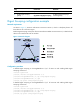
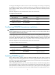
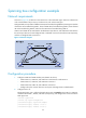
As shown in Figure 21, all devices on the network are in the same MST region. Device A and Device B
work at the distribution layer. Device C and Device D work at the access layer.
Configure MSTP so that packets of different VLANs are forwarded along different spanning trees: Packets
of VLAN 10 are forwarded along MSTI 1, those of VLAN 30 are forwarded along MSTI 3, those of VLAN
40 are forwarded along MSTI 4, and those of VLAN 20 are forwarded along MSTI 0.
VLAN 10 and VLAN 30 are terminated on the distribution layer devices, and VLAN 40 is terminated on
the access layer devices. The root bridges of MSTI 1 and MSTI 3 are Device A and Device B, respectively,
and the root bridge of MSTI 4 is Device C.
Figure 21 Network diagram
Configuration procedure
1. Configure VLANs and VLAN member ports (details not shown):
{ Create VLAN 10, VLAN 20, and VLAN 30 on both Device A and Device B.
{ Create VLAN 10, VLAN 20, and VLAN 40 on Device C.
{ Create VLAN 20, VLAN 30, and VLAN 40 on Device D.
{ Configure the ports on these devices as trunk ports and assign them to related VLANs.
2. Configure Device A:
# Enter MST region view, configure the MST region name as example, map VLAN 10, VLAN 30,
and VLAN 40 to MSTI 1, MSTI 3, and MSTI 4, respectively, and configure the revision level of the
MST region as 0.
<DeviceA> system-view
[DeviceA] stp region-configuration
[DeviceA-mst-region] region-name example
[DeviceA-mst-region] instance 1 vlan 10
[DeviceA-mst-region] instance 3 vlan 30
X
G
E
1
/
0
/
1
X
GE
1
/
0
/
1
X
G
E
1
/
0
/
1
X
G
E
1
/
0
/
1