
R21xx-HP FlexFabric 11900 Layer 2 LAN Switching Configuration Guide

127
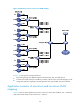
• For the uplink traffic, after you configure one-to-two VLAN mapping on the customer-side port, the
device tags the packet from a CVLAN with a SVLAN.
• For the downlink traffic, you can configure the customer-side port as a hybrid port and assign the
port to the SVLAN as an untagged member, so that the device strips the SVLAN tags before sending
packets. Also, you can configure the customer-side port as a trunk port and configure the SVLAN as
the PVID, so that the device strips the SVLAN tags before sending packets.
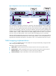
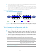
Two-to-two VLAN mapping
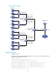
Figure 38 Two-to-two VLAN mapping implementation
In Figure 38, after you configure two-to-two VLAN mapping on the customer-side port, the device
replaces the CVLAN and the SVLAN with the CVLAN' and the SVLAN' for the uplink traffic and replaces
the SVLAN' and CVLAN' with the SVLAN and the CVLAN for the downlink traffic.
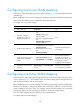
VLAN mapping configuration task list
When you configure VLAN mapping, follow these guidelines:
• VLAN mapping is mutually exclusive with EVB. Do not enable VLAN mapping and EVB on a port.
• When you configure both VLAN mapping and QinQ to add VLAN tags to packets, if the
configurations conflict, VLAN mapping takes effect. For more information about QinQ, see
"Configuring QinQ."
• When y
ou configure both VLAN mapping and a QoS policy to modify VLAN tags of packets or
add VLAN tags to packets, if the configurations conflict, the QoS policy takes effect. For information
about QoS policies, see ACL and QoS Configuration Guide.
Use the VLAN mapping methods as appropriate to the roles of your devices in the network.
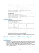
Task Remarks
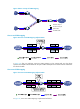
Configuring one-to-one VLAN mapping
Configure one-to-one VLAN mapping on the wiring-closet
switch as shown in Figure 33.
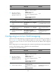
Configuring one-to-two VLAN mapping
Configure one-to-two VLAN mapping on PE1 and PE4,
through which traffic from customer networks enter the service
provider networks, as shown in Figure 34.
Configuring two-to-two VLAN mapping
Configure two-to-two VLAN mapping on PE3, edge device of
the SP 2 network, as shown in Figure 34.
Network-side port Customer-side port Uplink traffic Downlink traffic
SP network
SVLAN DataCVLAN
SVLAN DataCVLAN
Two-to-two VLAN
mapping
DataCVLAN’SVLAN’
DataCVLAN’SVLAN’
Customer
network