
R21xx-HP FlexFabric 11900 Layer 2 LAN Switching Configuration Guide


12
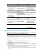
Step Command Remarks
1. Enter system view. system-view N/A
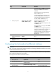
2. (Optional.) Set the traffic
polling interval of the storm
control module.
storm-constrain interval seconds
The default setting is 10 seconds.
For network stability, use the
default or set a higher traffic
polling interval (10 seconds).
3. Enter Ethernet interface view.
interface interface-type
interface-number
N/A
4. (Optional.) Enable storm
control, and set the lower and
upper thresholds for
broadcast, multicast, or
unknown unicast traffic.
storm-constrain { broadcast |
multicast | unicast } { pps | kbps |
ratio } max-pps-values
min-pps-values
By default, storm control is
disabled.
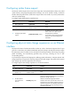
5. Set the control action to take
when monitored traffic
exceeds the upper threshold.
storm-constrain control { block |
shutdown }
By default, storm control is
disabled.
6. (Optional.) Enable the
interface to log storm control
threshold events.
storm-constrain enable log
By default, the interface outputs log
messages when monitored traffic
exceeds the upper threshold or
falls below the lower threshold
from the upper threshold.
7. (Optional.) Enable the
interface to send storm control
threshold event traps.
storm-constrain enable trap
By default, the interface sends
traps when monitored traffic
exceeds the upper threshold or
drops below the lower threshold
from the upper threshold.
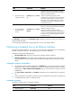
Setting the MDIX mode of an Ethernet interface
NOTE:
Fiber ports and 10-GE copper ports do not support the MDIX mode setting.
A physical Ethernet interface comprises eight pins, each of which plays a dedicated role. For example,
pins 1 and 2 transmit signals, and pins 3 and 6 receive signals. You can use both crossover and
straight-through Ethernet cables to connect copper Ethernet interfaces. To accommodate these types of
cables, a copper Ethernet interface can operate in one of the following Medium Dependent
Interface-Crossover (MDIX) modes:
• MDIX mode—Pins 1 and 2 are receive pins and pins 3 and 6 are transmit pins.
• MDI mode—Pins 1 and 2 are transmit pins and pins 3 and 6 are receive pins.
• AutoMDIX mode—The interface negotiates pin roles with its peer.
To enable the interface to communicate with its peer, set the MDIX mode of the interface mode by using
the following guidelines:
• Generally, set the MDIX mode of the interface to AutoMDIX. Set the MDIX mode of the interface to
MDI or MDIX only when the device cannot determine the cable type.
• When a straight-through cable is used, set the interface to operate in the MDIX mode different than
its peer.