
R21xx-HP FlexFabric 11900 Layer 3 IP Routing Configuration Guide

103
Intra Area: 2 Inter Area: 1 ASE: 0 NSSA: 0
The output shows that Switch B has learned the route 10.3.1.0/24 to Area 2.
Configuring OSPF GR
Network requirements
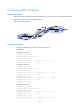
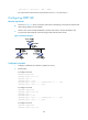
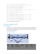
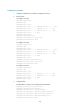
• As shown in Figure 27, Switch A, Switch B, and Switch C that belong to the same AS and the same
OSPF routing domain are GR capable.
• Switch A acts as the non-IETF GR Restarter; Switch B and Switch C are the GR Helpers and
re-synchronize their LSDB with Switch A through OOB communication of GR.
Figure 27 Network diagram
Configuration procedure
1. Configure IP addresses for interfaces. (Details not shown.)
2. Enable OSPF:
# Configure Switch A
SwitchA> system-view
[SwitchA] router id 1.1.1.1
[SwitchA] ospf 100
[SwitchA-ospf-100] area 0
[SwitchA-ospf-100-area-0.0.0.0] network 192.1.1.0 0.0.0.255
[SwitchA-ospf-100-area-0.0.0.0] quit
# Configure Switch B
<SwitchB> system-view
[SwitchB] router id 2.2.2.2
[SwitchB] ospf 100
[SwitchB-ospf-100] area 0
[SwitchB-ospf-100-area-0.0.0.0] network 192.1.1.0 0.0.0.255
[SwitchB-ospf-100-area-0.0.0.0] quit
# Configure Switch C
<SwitchC> system-view
[SwitchC] router id 3.3.3.3