
R21xx-HP FlexFabric 11900 Layer 3 IP Routing Configuration Guide


35
RIP configuration examples
Configuring basic RIP
Network requirements
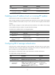
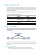
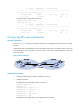
As shown in Figure 7, enable RIPv2 on all interfaces on Router A and Router B. Configure Switch B to not
advertise route 10.2.1.0/24 to Switch A, and to accept only route 2.1.1.0/24 from Switch A.
Figure 7 Network diagram
Configuration procedure
1. Configure IP addresses for interfaces. (Details not shown.)
2. Configure basic RIP:
# Configure Switch A.
<SwitchA> system-view
[SwitchA] rip
[SwitchA-rip-1] network 192.168.1.0
[SwitchA-rip-1] network 172.16.0.0
[SwitchA-rip-1] network 172.17.0.0
[SwitchA-rip-1] quit
# Configure Switch B.
<SwitchB> system-view
[SwitchB] rip
[SwitchB-rip-1] network 192.168.1.0
[SwitchB-rip-1] network 10.0.0.0
[SwitchB-rip-1] quit
# Display the RIP routing table of Switch A.
[SwitchA] display rip 1 route
Route Flags: R - RIP
A - Aging, S - Suppressed, G - Garbage-collect
----------------------------------------------------------------------------
Peer 192.168.1.2 on Vlan-interface100
Destination/Mask Nexthop Cost Tag Flags Sec
10.0.0.0/8 192.168.1.2 1 0 RA 11
The output shows that RIPv1 uses a natural mask.
3. Configure a RIP version: