
R21xx-HP FlexFabric 11900 Layer 3 IP Routing Configuration Guide


46
The output shows that Switch A communicates with Switch C through VLAN-interface 100. Then the link
over VLAN-interface 100 fails.
# Display RIP routes destined for 120.1.1.0/24 on Switch A.
<SwitchA> display ip routing-table 120.1.1.0 24 verbose
Summary Count : 1
Destination: 120.1.1.0/24
Protocol: RIP Process ID: 2
SubProtID: 0x1 Age: 04h20m37s
Cost: 1 Preference: 100
Tag: 0 State: Active Adv
OrigTblID: 0x0 OrigVrf: default-vrf
TableID: 0x2 OrigAs: 0
NBRID: 0x26000002 LastAs: 0
AttrID: 0xffffffff Neighbor: 192.168.2.2
Flags: 0x1008c OrigNextHop: 192.168.2.2
Label: NULL RealNextHop: 192.168.2.2
BkLabel: NULL BkNextHop: N/A
Tunnel ID: Invalid Interface: Vlan-interface200
BkTunnel ID: Invalid BkInterface: N/A
The output shows that Switch A communicates with Switch C through VLAN-interface 200.
Configuring RIP FRR
Network requirements
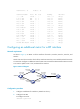
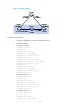
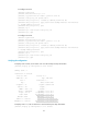
As shown in Figure 12, Switch S, Switch A, and Switch D run RIPv2. Configure RIP FRR so that when Link
A becomes unidirectional, services can be switched to Link B immediately.
Figure 12 Network diagram
Configuration procedure
1. Configure IP addresses and subnet masks for interfaces on the switches. (Details not shown.)
2. Configure RIPv2 on the switches to make sure Switch A, Switch D, and Switch S can communicate
with each other at Layer 3. (Details not shown.)
3. Configure RIP FRR: