
R21xx-HP FlexFabric 11900 Layer 3 IP Services Configuration Guide


207
Configuration procedure
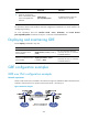
Before the configuration, make sure Switch A and Switch B can reach each other.
1. Configure Switch A:
# Configure interface VLAN-interface 100.
<SwitchA> system-view
[SwitchA] vlan 100
[SwitchA-vlan100] port Ten-GigabitEthernet 1/0/1
[SwitchA-vlan100] quit
[SwitchA] interface vlan-interface 100
[SwitchA-Vlan-interface100] ip address 10.1.1.1 255.255.255.0
[SwitchA-Vlan-interface100] quit
# Configure interface VLAN-interface 101.
[SwitchA] vlan 101
[SwitchA-vlan101] port Ten-GigabitEthernet 1/0/2
[SwitchA-vlan101] quit
[SwitchA] interface vlan-interface 101
[SwitchA-Vlan-interface101] ip address 1.1.1.1 255.255.255.0
[SwitchA-Vlan-interface101] quit
# Create service loopback group 1, and configure the service type as tunnel.
[SwitchA] service-loopback group 1 type tunnel
# Add port Ten-GigabitEthernet 1/0/3 to service loopback group 1.
[SwitchA] interface Ten-GigabitEthernet 1/0/3
[SwitchA-Ten-GigabitEthernet1/0/3] port service-loopback group 1
[SwitchA-Ten-GigabitEthernet1/0/3] quit
# Create a tunnel interface Tunnel1, and specify the tunnel mode as GRE over IPv4.
[SwitchA] interface tunnel 1 mode gre
# Configure an IP address for the tunnel interface.
[SwitchA-Tunnel1] ip address 10.1.2.1 255.255.255.0
# Configure the source address of tunnel interface as the IP address of VLAN-interface 101 on
Switch A.
[SwitchA-Tunnel1] source vlan-interface 101
# Configure the destination address of the tunnel interface as the IP address of VLAN-interface 101
on Switch B.
[SwitchA-Tunnel1] destination 2.2.2.2
[SwitchA-Tunnel1] quit
# Configure a static route from Switch A through the tunnel interface to Group 2.
[SwitchA] ip route-static 10.1.3.0 255.255.255.0 tunnel 1
2. Configure Switch B:
# Configure interface VLAN-interface 100.
<SwitchB> system-view
[SwitchB] vlan 100
[SwitchB-vlan100] port Ten-GigabitEthernet 1/0/1
[SwitchB-vlan100] quit