
R21xx-HP FlexFabric 11900 Layer 3 IP Services Configuration Guide


49
[SwitchA-dhcp-pool-0] gateway-list 10.1.1.126
[SwitchA-dhcp-pool-0] quit
Verifying the configuration
After the preceding configuration is complete, Switch B can obtain IP address 10.1.1.5 and other network
parameters, and Switch C can obtain IP address 10.1.1.6 and other network parameters from Switch A.
You can use the display dhcp server ip-in-use command on the DHCP server to view the IP addresses
assigned to the clients.
Dynamic IP address assignment configuration example
Network requirements
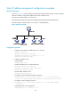
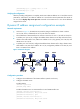
• As shown in Figure 19, the DHCP server (Switch A) assigns IP addresses to clients in subnet
10 .1.1. 0 / 2 4 , w h i c h i s s u b n e t t e d i n t o 10 .1.1. 0 / 2 5 a n d 10 .1.1.12 8 / 2 5 .
• The IP addresses of VLAN-interfaces 10 and 20 on Switch A are 10.1.1.1/25 and 10.1.1.129/25.
• In address pool 10.1.1.0/25, configure the address lease duration as ten days and twelve hours,
domain name suffix aabbcc.com, DNS server address 10.1.1.2/25, gateway 10.1.1.126/25, and
W I N S s e r v e r 10 .1.1. 4 / 2 5 .
• In address pool 10.1.1.128/25, configure the address lease duration as five days, domain name
suffix aabbcc.com, DNS server address 10.1.1.2/25, and gateway address 10.1.1.254/25, and
there is no WINS server address.
Figure 19 Network diagram
Configuration procedure
1. Configure the IP addresses of the VLAN interfaces. (Details not shown.)
2. Configure the DHCP server:
# Enable DHCP.
<SwitchA> system-view
[SwitchA] dhcp enable
# Enable the DHCP server on VLAN-interface 10 and VLAN-interface 20.
[SwitchA] interface vlan-interface 10
[SwitchA-Vlan-interface10] dhcp select server
[SwitchA-Vlan-interface10] quit
[SwitchA] interface vlan-interface 20
[SwitchA-Vlan-interface20] dhcp select server