
R21xx-HP FlexFabric 11900 MPLS Configuration Guide


130
Configuring an MPLS L3VPN over a GRE tunnel
Network requirements
CE 1 and CE 2 belong to VPN 1. The PEs support MPLS. The P switch does not support MPLS and
provides only IP functions.
On the backbone, use a GRE tunnel to encapsulate and forward VPN packets to implement MPLS
L3VPN.
Configure tunnel policies on the PEs, and specify the tunnel type for VPN traffic as GRE.
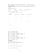
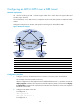
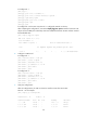
Figure 44 Network diagram
Device Interface IP address
Device
Interface
IP address
CE 1 Vlan-int12 10.1.1.1/24
P
Vlan-int11 172.1.1.2/24
PE 1 Loop0 1.1.1.9/32 Vlan-int12 172.2.1.1/24
Vlan-int12 10.1.1.2/24
PE 2
Loop0
2.2.2.9/32
Vlan-int11 172.1.1.1/24
Vlan-int11 10.2.1.2/24
Tunnel0 20.1.1.1/24 Vlan-int12 172.2.1.2/24
CE 2 Vlan-int12 10.2.1.1/24
Tunnel0
20.1.1.2/24
Configuration procedure
1. Configure an IGP on the MPLS backbone to ensure IP connectivity within the backbone:
This example uses OSPF. (Details not shown.)
After the configurations, OSPF adjacencies are established between PE 1, P, and PE 2. Execute the
display ospf peer command. The output shows that the adjacency status is Full. Execute the display
ip routing-table command. The output shows that the PEs have learned the routes to the loopback
interfaces of each other.
2. Configure basic MPLS on the PEs:
# Configure PE 1.
<PE1> system-view
[PE1] mpls lsr-id 1.1.1.9
# Configure PE 2.