
R21xx-HP FlexFabric 11900 MPLS Configuration Guide
133
# Configure PE 1.
[PE1] bgp 100
[PE1-bgp] peer 2.2.2.9 as-number 100
[PE1-bgp] peer 2.2.2.9 connect-interface loopback 0
[PE1-bgp] ipv4-family vpnv4
[PE1-bgp-vpnv4] peer 2.2.2.9 enable
[PE1-bgp-vpnv4] quit
[PE1-bgp] quit
# Configure PE 2 in the same way that PE 1 is configured. (Details not shown.)
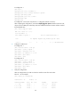
After completing the configuration, execute the display bgp peer vpnv4 command on the PEs. The
output shows that BGP peer relationship has been established between the PEs and has reached
the Established state.
[PE1] display bgp peer vpnv4
BGP local router ID: 1.1.1.9
Local AS number: 100
Total number of peers: 1 Peers in established state: 1
Peer AS MsgRcvd MsgSent OutQ PrefRcv Up/Down State
2.2.2.9 100 5 7 0 2 00:00:43 Established
6. Configure a GRE tunnel:
# Configure PE 1.
[PE1] interface tunnel 0 mode gre
[PE1-Tunnel0] source loopback 0
[PE1-Tunnel0] destination 2.2.2.9
[PE1-Tunnel0] ip address 20.1.1.1 24
[PE1-Tunnel0] mpls enable
[PE1-Tunnel0] quit
# Configure PE 2.
[PE2] interface tunnel 0 mode gre
[PE2-Tunnel0] source loopback 0
[PE2-Tunnel0] destination 1.1.1.9
[PE2-Tunnel0] ip address 20.1.1.2 24
[PE2-Tunnel0] mpls enable
[PE2-Tunnel0] quit
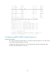
7. Verify the configuration:
After the configurations, the CEs can learn the interface routes from each other.
Take CE 1 as an example:
[CE1] display ip routing-table
Destinations : 13 Routes : 13
Destination/Mask Proto Pre Cost NextHop Interface
0.0.0.0/32 Direct 0 0 127.0.0.1 InLoop0
10.1.1.0/24 Direct 0 0 10.1.1.1 Vlan12
10.1.1.0/32 Direct 0 0 10.1.1.1 Vlan12