
R21xx-HP FlexFabric 11900 MPLS Configuration Guide


151
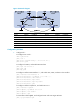
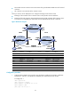
• PE 3 and PE 4 are the customer carrier's PE switches. They provide MPLS L3VPN services for the end
customers.
• CE 3 and CE 4 are customers of the customer carrier.
The key to carrier's carrier deployment is to configure exchange of two kinds of routes:
• Exchange of the customer carrier's internal routes on the provider carrier's backbone.
• Exchange of the end customers' VPN routes between PE 3 and PE 4, the PEs of the customer carrier.
In this process, an MP-IBGP peer relationship must be established between PE 3 and PE 4.
Figure 48 Network diagram
Device Interface IP address Device Interface IP address
CE 3 Vlan-int11 100.1.1.1/24
CE 4
Vlan-int11 120.1.1.1/24
PE 3 Loop0 1.1.1.9/32
PE 4
Loop0
6.6.6.9/32
Vlan-int11 100.1.1.2/24 Vlan-int11 120.1.1.2/24
Vlan-int12 10.1.1.1/24
Vlan-int12 20.1.1.2/24
CE 1 Loop0 2.2.2.9/32
CE 2
Loop0
5.5.5.9/32
Vlan-int12 10.1.1.2/24 Vlan-int11 21.1.1.2/24
Vlan-int11 11.1.1.1/24
Vlan-int12 20.1.1.1/24
PE 1 Loop0 3.3.3.9/32
PE 2
Loop0
4.4.4.9/32
Vlan-int11 11.1.1.2/24 Vlan-int12 30.1.1.2/24
Vlan-int12 30.1.1.1/24
Vlan-int11 21.1.1.1/24
Configuration procedure
1. Configure MPLS L3VPN on the provider carrier backbone. Enable IS-IS as the IGP, enable LDP
between PE 1 and PE 2, and establish an MP-IBGP peer relationship between the PEs:
# Configure PE 1.
<PE1> system-view
[PE1] interface loopback 0
[PE1-LoopBack0] ip address 3.3.3.9 32
[PE1-LoopBack0] quit
[PE1] mpls lsr-id 3.3.3.9