
R21xx-HP FlexFabric 11900 MPLS Configuration Guide


244
[CE2] interface vlan-interface 10
[CE2-Vlan-interface10] ip address 100.1.1.2 24
[CE2-Vlan-interface10] quit
Verify the configuration
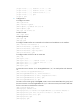
# Display L2VPN PW information on PE 1. The output shows that an LDP PW has been established.
[PE1] display l2vpn pw
Flags: M - main, B - backup, H - hub link, S - spoke link, N - no split horizon
Total number of PWs: 1, 1 up, 0 blocked, 0 down, 0 defect
Xconnect-group Name: vpn1
Peer PW ID In/Out Label Proto Flag Link ID State
192.3.3.3 1000 65662/65660 LDP M 1 Up
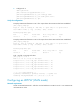
# Display L2VPN PW information on PE 2. The output shows that an LDP PW has been established.
[PE2] display l2vpn pw
Flags: M - main, B - backup, H - hub link, S - spoke link, N - no split horizon
Total number of PWs: 1, 1 up, 0 blocked, 0 down, 0 defect
Xconnect-group Name: vpn1
Peer PW ID In/Out Label Proto Flag Link ID State
192.2.2.2 1000 65669/65655 LDP M 1 Up
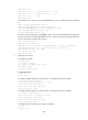
# CE 1 and CE 2 can ping each other.
[CE1] ping 100.1.1.2
56 bytes from 100.1.1.2: icmp_seq=0 ttl=255 time=8.000 ms
56 bytes from 100.1.1.2: icmp_seq=1 ttl=255 time=4.000 ms
56 bytes from 100.1.1.2: icmp_seq=2 ttl=255 time=19.000 ms
56 bytes from 100.1.1.2: icmp_seq=3 ttl=255 time=3.000 ms
56 bytes from 100.1.1.2: icmp_seq=4 ttl=255 time=6.000 ms
--- 100.1.1.2 ping statistics ---
5 packet(s) transmitted, 5 packet(s) received, 0.0% packet loss
round-trip min/avg/max/stddev = 3.000/8.000/19.000/5.762 ms
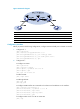
Configuring LDP PW redundancy
Network requirements
Create two LDP PWs to implement PW redundancy between CE 1 and CE 2. The primary PW goes
through PE 1—PE 2. The backup PW goes through PE 1—PE 3. When the primary PW fails, CE 1 and
CE 2 communicate through the backup PW.