
R21xx-HP FlexFabric 11900 MPLS Configuration Guide

245
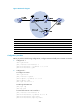
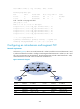
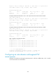
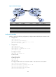
Figure 68 Network diagram
Device Interface IP address Device Interface IP address
CE 1 Vlan-int10 100.1.1.1/24
PE 2
Loop0
2.2.2.2/32
PE 1 Loop0 1.1.1.1/32
Vlan-int10 -
Vlan-int10 - Vlan-int12 12.1.1.2/24
Vlan-int12 12.1.1.1/24
PE 3
Loop0
3.3.3.3/32
Vlan-int13 13.1.1.1/24
Vlan-int10 -
CE 2 Vlan-int10 100.1.1.2/24 Vlan-int13 13.1.1.3/24
Configuration procedure
Before you perform the following configurations, configure VLANs and add ports to VLANs on switches.
1. Configure CE 1:
<CE1> system-view
[CE1] interface vlan-interface 10
[CE1-Vlan-interface10] ip address 100.1.1.1 24
[CE1-Vlan-interface10] quit
2. Configure PE 1:
# Configure an LSR ID.
<PE1> system-view
[PE1] interface loopback 0
[PE1-LoopBack0] ip address 1.1.1.1 32
[PE1-LoopBack0] quit
[PE1] mpls lsr-id 1.1.1.1
# Enable global MPLS LDP.
[PE1] mpls ldp
[PE1-ldp] quit
# Create LDP sessions to PE 2 and PE 3.
[PE1] interface vlan-interface 12
[PE1-Vlan-interface12] ip address 12.1.1.1 24
[PE1-Vlan-interface12] mpls enable
[PE1-Vlan-interface12] mpls ldp enable