
R21xx-HP FlexFabric 11900 MPLS Configuration Guide

250
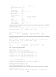
Total number of PWs: 2, 1 up, 1 blocked, 0 down, 0 defect
Xconnect-group Name: vpna
Peer PW ID In/Out Label Proto Flag Link ID State
2.2.2.2 20 65662/65660 LDP M 1 Blocked
3.3.3.3 30 65659/65655 LDP B 1 Up
# CE 1 and CE 2 can ping each other.
[CE1] ping 100.1.1.2
PING 100.1.1.2 (100.1.1.2): 56 data bytes
56 bytes from 100.1.1.2: icmp_seq=0 ttl=255 time=4.000 ms
56 bytes from 100.1.1.2: icmp_seq=1 ttl=255 time=9.000 ms
56 bytes from 100.1.1.2: icmp_seq=2 ttl=255 time=3.000 ms
56 bytes from 100.1.1.2: icmp_seq=3 ttl=255 time=5.000 ms
56 bytes from 100.1.1.2: icmp_seq=4 ttl=255 time=4.000 ms
--- 100.1.1.2 ping statistics ---
5 packet(s) transmitted, 5 packet(s) received, 0.0% packet loss
round-trip min/avg/max/stddev = 3.000/5.000/9.000/2.098 ms
Configuring an intra-domain multi-segment PW
Network requirements
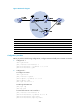
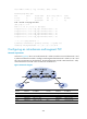
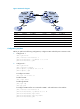
As shown in Figure 69, there is no tunnel between PE 1 and PE 2, and there is a tunnel between PE 1 and
P, and a tunnel between P and PE 2. Configure a multi-segment PW between PE 1 and PE 2, so CE 1 and
CE 2 can communicate over the backbone. The multi-segment PW includes a PW between PE 1 and P,
and a PW between P and PE 2. The two PWs are connected on P.
Figure 69 Network diagram
Device Interface IP address
Device
Interface
IP address
CE 1 Vlan-int10 100.1.1.1/24 P Loop0 192.4.4.4/32
PE 1 Loop0 192.2.2.2/32
Vlan-int23 23.1.1.2/24
Vlan-int23 23.1.1.1/24
Vlan-int26 26.2.2.2/24
CE 2 Vlan-int10 100.1.1.2/24 PE 2 Loop0 192.3.3.3/32
Vlan-int26 26.2.2.1/24