
R21xx-HP FlexFabric 11900 MPLS Configuration Guide


260
Configuring VPLS
Overview
Virtual Private LAN Service (VPLS) provides point-to-multipoint L2VPN services over an MPLS or IP
backbone. The provider backbone emulates a switch to connect all geographically dispersed sites of
each customer network. The backbone is transparent to the customer sites and the sites can communicate
with each other as if they were on the same LAN.
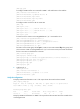
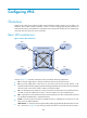
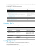
Basic VPLS architecture
Figure 71 Basic VPLS architecture
As show in Figure 71, the VPLS architecture mainly includes the following components:
• CE—A customer edge device is directly connected to the service provider network.
• PE—A provider edge device connects one or more CEs to the service provider network. A PE
implements VPN access by mapping and forwarding packets between private networks and public
network tunnels. A PE can be a UPE or NPE in a hierarchical VPLS.
• AC—An attachment circuit, physical or virtual, connects a CE and a PE, such as an Ethernet link or
a VLAN. On the HP 11900 series, an AC is a service instance on a Layer 2 Ethernet port.
• PW—A pseudowire is a bidirectional virtual connection between two PEs. An MPLS PW consists of
two unidirectional MPLS LSPs in opposite directions.
• Tunnel—A tunnel can be an LSP tunnel, an MPLS TE tunnel, or a GRE tunnel. It carries one or more
PWs over an IP/MPLS backbone.
• VPLS instance—A customer network might include multiple geographically dispersed sites (such as
site 1 and site 3 in Figure 71.) T
he service provider uses VPLS to connect all the sites to create a
VPN 1
CE 1
PE 3
PE 1 PE 2
CE 2
MPLS or IP backbone
PW
PE 4
PW
PW PW
Site 1
VPN 2
Site 2
CE 3
VPN 1
Site 3
VPN 2
CE 4
Site 4
AC
AC AC
AC
PWPW
Tunnel
Tunnel
Tunnel
Tunnel