
R21xx-HP FlexFabric 11900 MPLS Configuration Guide

39
For commands that display information about a routing table, see Layer 3—IP Routing Command
Reference.
IPv6 MCE configuration example
Network requirements
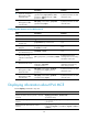
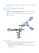
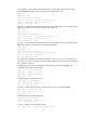
As shown in Figure 6, the IPv6 MCE device is connected to VPN 1 through VLAN-interface 10 and to
VPN 2 through VLAN-interface 20. RIPng is used in VPN 2.
Configure the IPv6 MCE to separate routes from different VPNs and advertise VPN routes to PE 1 through
OSPFv3.
Figure 6 Network diagram
Configuration procedure
Assume that the system name of the IPv6 MCE device is MCE, the system names of the edge devices of
VPN 1 and VPN 2 are VR1 and VR2, respectively, and the system name of PE 1 is PE1.
1. Configure the VPN instances on the MCE and PE 1:
# On the MCE, configure VPN instances vpn1 and vpn2, and specify an RD and route targets for
each VPN instance.
<MCE> system-view
[MCE] ip vpn-instance vpn1