
R21xx-HP FlexFabric 11900 MPLS Configuration Guide

74
LDP configuration examples
LDP LSP configuration example
Network requirements
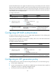
Switch A, Switch B, and Switch C all support MPLS.
Configure LDP to establish LSPs between Switch A and Switch C, so subnets 11.1.1.0 / 24 a n d 21.1.1.0 / 24
can reach each other over MPLS.
Configure LDP to establish LSPs for only destinations 1.1.1.9/32, 2.2.2.9/32, 3.3.3.9/32, 11.1.1.0 / 24 ,
and 21.1.1.0/24 on Switch A, Switch B, and Switch C.
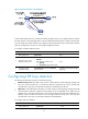
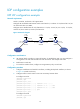
Figure 22 Network diagram
Configuration considerations
• LDP assigns labels according to routing information. To establish LDP LSPs, you must configure a
routing protocol to make sure the LSRs can reach each other. This example uses OSPF.
• Enable LDP on each LSR.
• To control the number of LSPs, configure an LSP generation policy on each LSR.
Configuration procedure
1. Configure IP addresses and masks for interfaces, including the loopback interfaces, as shown
in Figure 22. (Details not
shown.)
2. Configure OSPF on each switch to ensure IP connectivity between them:
# Configure Switch A.
<SwitchA> system-view
[SwitchA] ospf
[SwitchA-ospf-1] area 0
[SwitchA-ospf-1-area-0.0.0.0] network 1.1.1.9 0.0.0.0
[SwitchA-ospf-1-area-0.0.0.0] network 10.1.1.0 0.0.0.255
[SwitchA-ospf-1-area-0.0.0.0] network 11.1.1.0 0.0.0.255
[SwitchA-ospf-1-area-0.0.0.0] quit
[SwitchA-ospf-1] quit
# Configure Switch B.
<SwitchB> system-view
[SwitchB] ospf
Loop0
2.2.2.9/32
Vlan-int3
20.1.1.1/24
Loop0
3.3.3.9/32
Loop0
1.1.1.9/32
Vlan-int2
10.1.1.1/24
Vlan-int2
10.1.1.2/24
Vlan-int3
20.1.1.2/24
Switch A Switch B Switch C
11.1.1.0/24 21.1.1.0/24
Vlan-int4
11.1.1.1/24
Vlan-int5
21.1.1.1/24