
R21xx-HP FlexFabric 11900 MPLS Configuration Guide
82
2. Enable LDP on each switch.
3. Configure LSP generation policies so LDP uses only the routes 11.1.1.0/24 and 21.1.1.0/24 to
establish LSPs.
4. Configure label advertisement policies, so LDP sets up LSPs only over the link Switch A—Switch
B—Switch C, as follows:
{ Switch A advertises only the label mapping for FEC 11.1.1. 0 / 24 t o Swi tch B.
{ Switch C advertises only the label mapping for FEC 21.1.1.0/24 to Switch B.
{ Switch D does not advertise label mapping for FEC 21.1.1.0/24 to Switch A. Switch D does not
advertise label mapping for FEC 11.1.1.0 / 24 t o Sw i t c h C.
Configuration procedure
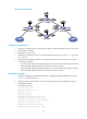
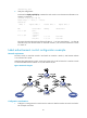
1. Configure IP addresses and masks for interfaces, including the loopback interfaces, as shown
in Figure 24. (Details not
shown.)
2. Configure OSPF on each switch to ensure IP connectivity between them. (Details not shown.)
3. Enable MPLS and LDP:
# Configure Switch A.
<SwitchA> system-view
[SwitchA] mpls lsr-id 1.1.1.9
[SwitchA] mpls ldp
[SwitchA-ldp] quit
[SwitchA] interface vlan-interface 2
[SwitchA-Vlan-interface2] mpls enable
[SwitchA-Vlan-interface2] mpls ldp enable
[SwitchA-Vlan-interface2] quit
[SwitchA] interface vlan-interface 6
[SwitchA-Vlan-interface6] mpls enable
[SwitchA-Vlan-interface6] mpls ldp enable
[SwitchA-Vlan-interface6] quit
# Configure Switch B.
<SwitchB> system-view
[SwitchB] mpls lsr-id 2.2.2.9
[SwitchB] mpls ldp
[SwitchB-ldp] quit
[SwitchB] interface vlan-interface 2
[SwitchB-Vlan-interface2] mpls enable
[SwitchB-Vlan-interface2] mpls ldp enable
[SwitchB-Vlan-interface2] quit
[SwitchB] interface vlan-interface 3
[SwitchB-Vlan-interface3] mpls enable
[SwitchB-Vlan-interface3] mpls ldp enable
[SwitchB-Vlan-interface3] quit
# Configure Switch C.
<SwitchC> system-view
[SwitchC] mpls lsr-id 3.3.3.9
[SwitchC] mpls ldp
[SwitchC-ldp] quit
[SwitchC] interface vlan-interface 3