HP FlexFabric 11900 Switch Series Network Management and Monitoring Configuration Guide Part number: 5998-4067 Software version: Release 2105 and later Document version: 6W100-20130515
Legal and notice information © Copyright 2013 Hewlett-Packard Development Company, L.P. No part of this documentation may be reproduced or transmitted in any form or by any means without prior written consent of Hewlett-Packard Development Company, L.P. The information contained herein is subject to change without notice.
Contents Using ping, tracert, and system debugging ··············································································································· 1 Ping ····················································································································································································· 1 Using a ping command to test network connectivity ···························································································· 1 Ping example
Configuration example for MPLS VPN time synchronization in client/server mode ·············································· 46 Configuration example for MPLS VPN time synchronization in symmetric active/passive mode ························· 47 Configuring SNTP ······················································································································································ 50 Configuration restrictions and guidelines ····················································
Enabling the NQA client ··············································································································································· 83 Configuring the ICMP echo operation ························································································································· 84 Configuring the UDP echo operation ··························································································································· 84 Configuring option
Configuring Layer 3 remote port mirroring ··············································································································· 118 Layer 3 remote port mirroring configuration task list ······················································································ 119 Configuration prerequisites ································································································································ 119 Configuring local mirroring groups ·············
Conventions ·································································································································································· 139 Index ········································································································································································ 141 v
Using ping, tracert, and system debugging This chapter covers ping, tracert, and information about debugging the system. Ping Use the ping utility to determine if a specific address is reachable. Ping sends ICMP echo requests (ECHO-REQUEST) to the destination device. Upon receiving the requests, the destination device responds with ICMP echo replies (ECHO-REPLY) to the source device.
Figure 1 Network diagram Configuration procedure # Use the ping command on Device A to test connectivity to Device C. PING 1.1.2.2 (1.1.2.2): 56 data bytes, press CTRL_C to break 56 bytes from 1.1.2.2: icmp_seq=0 ttl=254 time=2.137 ms 56 bytes from 1.1.2.2: icmp_seq=1 ttl=254 time=2.051 ms 56 bytes from 1.1.2.2: icmp_seq=2 ttl=254 time=1.996 ms 56 bytes from 1.1.2.2: icmp_seq=3 ttl=254 time=1.963 ms 56 bytes from 1.1.2.2: icmp_seq=4 ttl=254 time=1.991 ms --- 1.1.2.
2. The intermediate device (Device B) adds the IP address of its outbound interface (1.1.2.1) to the RR option of the ICMP echo request, and forwards the packet. 3. Upon receiving the request, the destination device copies the RR option in the request and adds the IP address of its outbound interface (1.1.2.2) to the RR option. Then the destination device sends an ICMP echo reply. 4. The intermediate device adds the IP address of its outbound interface (1.1.1.
6. The source device thinks that the packet has reached the destination device after receiving the port-unreachable ICMP message, and the path to the destination device is 1.1.1.2 to 1.1.2.2 to 1.1.3.2. Prerequisites Before you use a tracert command, perform the tasks in this section. For an IPv4 network: • Enable sending of ICMP timeout packets on the intermediate devices (devices between the source and destination devices).
Figure 3 Network diagram 1.1.1.1/24 1.1.1.2/24 Device A 1.1.2.1/24 1.1.2.2/24 Device B Device C Configuration procedure 1. Use the ping command to test connectivity between Device A and Device C. ping 1.1.2.2 PING 1.1.2.2(1.1.2.2): 56 -data bytes, press CTRL_C to break Request time out Request time out Request time out Request time out Request time out --- 1.1.2.2 ping statistics --5 packet(s) transmitted,0 packet(s) received,100.
Debugging information control switches The following switches control the display of debugging information: • Module debugging switch—Controls whether to generate the module-specific debugging information. • Screen output switch—Controls whether to display the debugging information on a certain screen. Use terminal monitor and terminal logging level commands to turn on the screen output switch. For more information about these two commands, see Network Management and Monitoring Command Reference.
Configuring NTP Synchronize your device with a trusted time source by using the Network Time Protocol (NTP) or changing the system time before you run it on a live network. Various tasks, including network management, charging, auditing, and distributed computing depend on an accurate system time setting, because the timestamps of system messages and logs use the system time. Overview NTP is typically used in large networks to dynamically synchronize time among network devices.
1. Device A sends Device B an NTP message, which is timestamped when it leaves Device A. The time stamp is 10:00:00 am (T1). 2. When this NTP message arrives at Device B, Device B adds a timestamp showing the time when the message arrived at Device B. The timestamp is 11:00:01 am (T2). 3. When the NTP message leaves Device B, Device B adds a timestamp showing the time when the message left Device B. The timestamp is 11:00:02 am (T3). 4.
the device selects is called the reference source. For more information about clock selection, see the related protocols and standards. If the devices in a network cannot synchronize to an authoritative time source, you can select a device that has a relatively accurate clock from the network, and use the local clock of the device as the reference clock to synchronize other devices in the network.
Mode Broadcast Working process Principle A server periodically sends clock synchronization messages to the broadcast address 255.255.255.255. Clients listen to the broadcast messages from the servers to synchronize to the server according to the broadcast messages. When a client receives the first broadcast message, the client and the server start to exchange messages to calculate the network delay between them. Then, only the broadcast server sends clock synchronization messages.
• If the IP address of the peer device matches a permit statement in an ACL for more than one access right, the least restrictive access right is granted to the peer device. If a deny statement or no ACL is matched, no access right is granted. • If no ACL is created for a specific access right, the associated access right is not granted. • If no ACL is created for any access right, peer is granted. This feature provides minimal security for a system running NTP.
Figure 8 Network diagram Protocols and standards • RFC 1305, Network Time Protocol (Version 3) Specification, Implementation and Analysis • RFC 5905, Network Time Protocol Version 4: Protocol and Algorithms Specification Configuration restrictions and guidelines • You cannot configure both NTP and SNTP on the same device. • Do not configure NTP on an aggregate member port. • The NTP service and SNTP service are mutually exclusive. You can only enable either NTP service or SNTP service at a time.
Step Enable the NTP service. 2. Command Remarks ntp-service enable By default, the NTP service is not enabled. Configuring NTP association modes This section describes how to configure NTP association modes. Configuring NTP in client/server mode When the device operates in client/server mode, specify the IP address for the server on the client.
• Execute the ntp-service enable command on a symmetric passive peer to enable NTP. Otherwise, the symmetric-passive peer will not process NTP messages from a symmetric-active peer. • Either the symmetric-active peer, or the symmetric-passive peer, or both of them must be in synchronized state. Otherwise, their time cannot be synchronized. • You can configure multiple symmetric-passive peers by repeating the ntp-service unicast-peer or ntp-service ipv6 unicast-peer command.
Step 3. Command Configure the device to operate in broadcast client mode. Remarks By default, the device does not operate in broadcast client mode. ntp-service broadcast-client After you execute the command, the device receives NTP broadcast messages from the specified interface. Command Remarks Configuring the broadcast server Step 1. Enter system view. system-view N/A 2. Enter VLAN interface view or Layer 3 Ethernet interface view.
Step Command Remarks 1. Enter system view. system-view N/A 2. Enter VLAN interface view or Layer 3 Ethernet interface view. interface interface-type interface-number Enter the interface for sending NTP multicast message. • Configure the device to operate 3. Configure the device to operate in multicast server mode.
Configuring NTP authentication in client/server mode When you configure NTP authentication in client/server mode, enable NTP authentication, configure an authentication key, set the key as a trusted key on both client and server, and associate the key with the NTP server on the client. The key IDs and key values configured on the server and client must be the same. Otherwise, NTP authentication fails. To configure NTP authentication for a client: Step Command Remarks 1. Enter system view.
Table 2 NTP authentication results Client Enable NTP authenticati on Yes Yes Yes Yes Yes No Server Configure a key and configure it as a trusted key Yes Yes Yes No N/A N/A Associate the key with an NTP server Yes Enable NTP authenticati on Yes Yes Yes Yes No Yes N/A No N/A N/A N/A Configure a key and configure it as a trusted key Authentication result Yes Succeeded. NTP messages can be sent and received correctly. No Failed. NTP messages cannot be sent and received correctly.
Step Command Remarks 3. Configure an NTP authentication key. ntp-service authentication-keyid keyid authentication-mode md5 { cipher | simple } value By default, no NTP authentication key is configured. 4. Configure the key as a trusted key. ntp-service reliable authentication-keyid keyid By default, no authentication key is configured as a trusted key. • Associate the specified key with 5. Associate the specified key with a passive peer.
Active peer Passive peer Enable NTP authentic ation Configure a key and configure it as a trusted key Associate the key with an passive peer Enable NTP authentication Configure a key and configure it as a trusted key Yes Yes Yes Yes No Failed. NTP messages cannot be sent and received correctly. Yes Yes Yes No N/A Failed. NTP messages cannot be sent and received correctly. Yes N/A No Yes N/A Failed. NTP messages cannot be sent and received correctly.
Step Command Remarks 1. Enter system view. system-view N/A 2. Enable NTP authentication. ntp-service authentication enable By default, NTP authentication is disabled. 3. Configure an NTP authentication key. ntp-service authentication-keyid keyid authentication-mode md5 { cipher | simple } value By default, no NTP authentication key is configured. 4. Configure the key as a trusted key.
Broadcast server Broadcast client Enable NTP authentic ation Configure a key and configure it as a trusted key Associate the key with a broadcast server Enable NTP authenticati on Configure a key and configure it as a trusted key Yes No Yes Yes N/A Failed. NTP messages cannot be sent and received correctly. Yes No Yes No N/A No authentication. NTP messages can be sent and received correctly. Yes N/A No Yes N/A Failed. NTP messages cannot be sent and received correctly.
Step Command Remarks 2. Enable NTP authentication. ntp-service authentication enable By default, NTP authentication is disabled. 3. Configure an NTP authentication key. ntp-service authentication-keyid keyid authentication-mode md5 { cipher | simple } value By default, no NTP authentication key is configured. 4. Configure the key as a trusted key. ntp-service reliable authentication-keyid keyid By default, no authentication key is configured as a trusted key. 5.
Multicast server Enable NTP authentic ation Yes Yes Yes No No Configure a key and configure it as a trusted key No N/A N/A N/A N/A Multicast client Associate the key with a multicast server Yes Enable NTP authenticatio n No No Yes No No N/A Yes N/A No Configure a key and configure it as a trusted key Authentication result N/A No authentication. NTP messages can be sent and received correctly. N/A Failed. NTP messages cannot be sent and received correctly. N/A No authentication.
To specify the source interface for NTP messages: Step Enter system view. 1. Command Remarks system-view N/A • Specify the source interface for Specify the source interface for NTP messages. 2. NTP messages: ntp-service source-interface interface-type interface-number • Specify the source interface for By default, no source interface is specified for NTP messages.
Perform this task to restrict the number of dynamic associations to prevent dynamic associations from occupying too many system resources. To configure the maximum number of dynamic associations: Step Command Remarks 1. Enter system view. system-view N/A 2. Configure the maximum number of dynamic sessions allowed to be established. ntp-service max-dynamic-sessions number By default, the command can establish up to 100 dynamic sessions.
NTP client/server mode configuration example Network requirements As shown in Figure 9, the local clock of Device A is to be used as a reference source, with the stratum level 2. Device B operates in client mode and Device A is to be used as the NTP server for Device B. Figure 9 Network diagram Configuration procedure 1. Set the IP address for each interface as shown in Figure 9. (Details not shown.) 2. Configure Device A: # Enable the NTP service.
source reference stra reach poll now offset delay disper ******************************************************************************** [12345]1.0.1.11 127.127.1.0 2 1 64 15 -4.0 0.0038 16.262 Notes: 1 source(master), 2 source(peer), 3 selected, 4 candidate, 5 configured. Total sessions : 1 The output shows that an association has been set up between Device B and Device A.
Leap indicator: 00 Clock jitter: 0.000977 s Stability: 0.000 pps Clock precision: 2^-10 Root delay: 0.02649 ms Root dispersion: 12.24641 ms Reference time: d0c60419.9952fb3e Wed, Dec 29 2010 19:01:45.598 The output shows that Device B has been synchronized to Device A, the clock stratum level of Device B is 3, and that of Device A is 2. # Display IPv6 NTP association information for Device B.
Figure 11 Network diagram Configuration procedure 1. Set the IP address for each interface as shown in Figure 11. (Details not shown.) 2. Configure Device A: # Enable the NTP service. system-view [DeviceA] ntp-service enable # Specify the local clock as the reference source, with the stratum level 3. [DeviceA] ntp-service refclock-master 3 3. Configure Device B: # Enable the NTP service. [DeviceB] ntp-service enable # Specify Device A as the NTP server of Device B.
Local mode: sym_passive Reference clock ID: 3.0.1.33 Leap indicator: 00 Clock jitter: 0.000916 s Stability: 0.000 pps Clock precision: 2^-17 Root delay: 0.00609 ms Root dispersion: 1.95859 ms Reference time: 83aec681.deb6d3e5 Sun, Jan 4 1970 5:56:17.869 # Display IPv4 NTP association information for Device B. [DeviceB] display ntp-service sessions source reference stra reach poll now offset delay disper ******************************************************************************** [25]3.0.1.
Figure 12 Network diagram Configuration procedure 1. Set the IP address for each interface as shown in Figure 12. (Details not shown.) 2. Configure Device A: # Enable the NTP service. system-view [DeviceA] ntp-service enable # Specify the local clock as the reference source, with the stratum level 3. [DeviceA] ntp-service refclock-master 3 3. Configure Device B: # Enable the NTP service.
Clock stratum: 3 System peer: 3000::36 Local mode: sym_passive Reference clock ID: 163.29.247.19 Leap indicator: 11 Clock jitter: 0.000977 s Stability: 0.000 pps Clock precision: 2^-10 Root delay: 0.01855 ms Root dispersion: 9.23483 ms Reference time: d0c6047c.97199f9f Wed, Dec 29 2010 19:03:24.590 # Display IPv6 NTP association information for Device B. [DeviceB] display ntp-service ipv6 sessions Notes: 1 source(master), 2 source(peer), 3 selected, 4 candidate, 5 configured.
Figure 13 Network diagram Configuration procedure 1. Set the IP address for each interface as shown in Figure 13. (Details not shown.) 2. Configure Switch C: # Enable the NTP service. system-view [SwitchC] ntp-service enable # Specify the local clock as the reference source, with the stratum level 2. [SwitchC] ntp-service refclock-master 2 # Configure Switch C to operate in broadcast server mode and send broadcast messages through VLAN-interface 2.
# Switch A and Switch B get synchronized upon receiving a broadcast message from Switch C. Display the NTP status of Switch A after clock synchronization. [SwitchA-Vlan-interface2] display ntp-service status Clock status: synchronized Clock stratum: 3 System peer: 3.0.1.31 Local mode: bclient Reference clock ID: 3.0.1.31 Leap indicator: 00 Clock jitter: 0.044281 s Stability: 0.000 pps Clock precision: 2^-10 Root delay: 0.00229 ms Root dispersion: 4.12572 ms Reference time: d0d289fe.
Figure 14 Network diagram Vlan-int2 3.0.1.31/24 Switch C NTP multicast server Vlan-int3 1.0.1.11/24 Vlan-int3 1.0.1.10/24 Switch A NTP multicast client Vlan-int2 3.0.1.30/24 Switch B Vlan-int2 3.0.1.32/24 Switch D NTP multicast client Configuration procedure 1. Set the IP address for each interface as shown in Figure 14. (Details not shown.) 2. Configure Switch C: # Enable the NTP service.
Leap indicator: 00 Clock jitter: 0.044281 s Stability: 0.000 pps Clock precision: 2^-10 Root delay: 0.00229 ms Root dispersion: 4.12572 ms Reference time: d0d289fe.ec43c720 Sat, Jan 8 2011 7:00:14.922 The output shows that Switch D has been synchronized to Switch C, the clock stratum level of Switch D is 3, and that of Switch C is 2. # Display IPv4 NTP association information for Switch D.
# Display the NTP status of Switch A after clock synchronization. [SwitchA-Vlan-interface3] display ntp-service status Clock status: synchronized Clock stratum: 3 System peer: 3.0.1.31 Local mode: bclient Reference clock ID: 3.0.1.31 Leap indicator: 00 Clock jitter: 0.165741 s Stability: 0.000 pps Clock precision: 2^-10 Root delay: 0.00534 ms Root dispersion: 4.51282 ms Reference time: d0c61289.10b1193f Wed, Dec 29 2010 20:03:21.
Figure 15 Network diagram Configuration procedure 1. Set the IP address for each interface as shown in Figure 15. (Details not shown.) 2. Configure Switch C: # Enable the NTP service. system-view [SwitchC] ntp-service enable # Specify the local clock as the reference source, with the stratum level 2. [SwitchC] ntp-service refclock-master 2 # Configure Switch C to operate in IPv6 multicast server mode and send multicast messages through VLAN-interface 2.
Leap indicator: 00 Clock jitter: 0.000977 s Stability: 0.000 pps Clock precision: 2^-10 Root delay: 0.00000 ms Root dispersion: 8.00578 ms Reference time: d0c60680.9754fb17 Wed, Dec 29 2010 19:12:00.591 The output shows that Switch D has been synchronized to Switch C, the clock stratum level of Switch D is 3, and that of Switch C is 2. # Display NTP association information for Switch D.
[SwitchA] interface vlan-interface 3 [SwitchA-Vlan-interface3] ntp-service ipv6 multicast-client ff24::1 7. Verify the configuration: # Display the NTP status of Switch A after clock synchronization. [SwitchA-Vlan-interface3] display ntp-service status Clock status: synchronized Clock stratum: 3 System peer: 3000::2 Local mode: bclient Reference clock ID: 165.84.121.65 Leap indicator: 00 Clock jitter: 0.165741 s Stability: 0.000 pps Clock precision: 2^-10 Root delay: 0.00534 ms Root dispersion: 4.
Figure 16 Network diagram Configuration procedure 1. Set the IP address for each interface as shown in Figure 16. (Details not shown.) 2. Configure Device A: # Enable the NTP service. system-view [DeviceA] ntp-service enable # Specify the local clock as the reference source, with the stratum level 2. [DeviceA] ntp-service refclock-master 2 3. Configure Device B: # Enable the NTP service. system-view [DeviceB] ntp-service enable # Enable NTP authentication on Device B.
Reference clock ID: 1.0.1.11 Leap indicator: 00 Clock jitter: 0.005096 s Stability: 0.000 pps Clock precision: 2^-10 Root delay: 0.00655 ms Root dispersion: 1.15869 ms Reference time: d0c62687.ab1bba7d Wed, Dec 29 2010 21:28:39.668 The output shows that Device B has been synchronized to Device A, the clock stratum level of Device B is 3, and that of Device A is 2. # Display IPv4 NTP association information for Device B.
Figure 17 Network diagram Vlan-int2 3.0.1.31/24 Switch C NTP broadcast server Vlan-int2 3.0.1.30/24 Switch A NTP broadcast client Vlan-int2 3.0.1.32/24 Switch B NTP broadcast client Configuration procedure 1. Set the IP address for each interface as shown in Figure 17. (Details not shown.) 2. Configure Switch A: # Enable the NTP service. system-view [SwitchA] ntp-service enable # Enable NTP authentication on Switch A.
system-view [SwitchC] ntp-service enable # Specify the local clock as the reference source, with the stratum level 3. [SwitchC] ntp-service refclock-master 3 # Configure Switch C to operate in NTP broadcast server mode and use VLAN-interface 2 to send NTP broadcast packets. [SwitchC] interface vlan-interface 2 [SwitchC-Vlan-interface2] ntp-service broadcast-server [SwitchC-Vlan-interface2] quit 5.
source reference stra reach poll now offset delay disper ******************************************************************************** [1245]3.0.1.31 127.127.1.0 3 3 64 68 -0.0 0.0000 0.0 Notes: 1 source(master),2 source(peer),3 selected,4 candidate,5 configured. Total sessions : 1 The output shows that an association has been set up between Switch B and Switch C.
# Enable the NTP service. system-view [PE2] ntp-service enable # Specify CE 1 in VPN 1 as the NTP server of PE 2. [PE2] ntp-service unicast-server 10.1.1.1 vpn-instance vpn1 4. Verify the configuration: # Display the IPv4 NTP association information and status on PE 2 a certain period of time later. [PE2] display ntp-service status Clock status: synchronized Clock stratum: 3 System peer: 10.1.1.1 Local mode: client Reference clock ID: 10.1.1.1 Leap indicator: 00 Clock jitter: 0.
Figure 19 Network diagram Configuration procedure 1. Set the IP address for each interface as shown in Figure 19. (Details not shown.) 2. Configure CE 1: # Enable the NTP service. system-view [CE1] ntp-service enable # Specify the local clock as the reference source, with the stratum level 2. [CE1] ntp-service refclock-master 2 3. Configure PE 1: # Enable the NTP service. system-view [PE1] ntp-service enable # Specify CE 1 in VPN 1 as the symmetric-passive peer of PE 1.
[PE1] display ntp-service sessions source reference stra reach poll now offset delay disper ******************************************************************************** [1245]10.1.1.1 127.127.1.0 2 1 64 519 -0.0 0.0000 Notes: 1 source(master),2 source(peer),3 selected,4 candidate,5 configured. Total sessions : 1 [PE1] display ntp-service trace Server 127.0.0.1 Stratum 3 , jitter Server 10.1.1.1 Stratum 2 , jitter 939.00, synch distance 0.0000. RefID 127.127.1.0 0.
Configuring SNTP SNTP is a simplified, client-only version of NTP specified in RFC 4330. SNTP supports only the client/server mode. An SNTP-enabled device can receive time from NTP servers, but cannot provide time services to other devices. SNTP uses the same packet format and packet exchange procedure as NTP, but provides faster synchronization at the price of time accuracy. If you specify multiple NTP servers for an SNTP client, the server with the best stratum is selected.
Step Command Remarks • For IPv4: Specify an NTP server for the device. 2. sntp unicast-server { ip-address | server-name } [ vpn-instance vpn-instance-name ] [ authentication-keyid keyid | source interface-type interface-number | version number ] * • For IPv6: sntp ipv6 unicast-server { ipv6-address | server-name } [ vpn-instance vpn-instance-name ] [ authentication-keyid keyid | source interface-type interface-number ] * By default, no NTP server is specified for the device.
Step Command Remarks • For IPv4: Associate the SNTP authentication key with the specific NTP server. 5. sntp unicast-server { ip-address | server-name } [ vpn-instance vpn-instance-name ] authentication-keyid keyid • For IPv6: sntp ipv6 unicast-server { ipv6-address | server-name } [ vpn-instance vpn-instance-name ] authentication-keyid keyid By default, no NTP server is specified. Displaying and maintaining SNTP Execute display commands in any view.
# Configure an NTP authentication key, with the key ID of 10 and key value of aNiceKey. Input the key in plain text. [DeviceA] ntp-service authentication-keyid 10 authentication-mode md5 simple aNiceKey # Specify the key as a trusted key. [DeviceA] ntp-service reliable authentication-keyid 10 3. Configure Device B: # Enable the SNTP service. system-view [DeviceB] sntp enable # Enable SNTP authentication on Device B.
Configuring the information center The information center on a device classifies and manages logs for all modules so that network administrators can monitor network performance and troubleshoot network problems. Overview The information center receives logs generated by source modules and outputs logs to different destinations according to user-defined output rules. You can classify, filter, and output logs based on source modules. To view the supported source modules, use info-center source ?.
Severity value Level Description 4 Warning Warning condition. For example, an interface is disconnected, or the memory resources are used up. 5 Notification Normal but significant condition. For example, a terminal logs in to the device, or the device reboots. 6 Informational Informational message. For example, a command or a ping operation is executed. 7 Debug Debug message.
Output destination Format Example Log host Timestamp Sysname %%vvModule/Level/Digest: Source; Content <190>Nov 24 16:22:21 2010 HP %%10SYSLOG/6/SYSLOG_RES TART: -DevIP=1.1.1.1; System restarted –HP Comware Software. Table 9 describes the fields in a log message.
Table 10 Timestamp precisions and configuration commands Item Destined to the log host Destined to the console, monitor terminal, log buffer, and log file Precision Seconds Milliseconds Command used to set the timestamp format info-center timestamp loghost info-center timestamp Table 11 Description of the timestamp parameters Timestamp parameters boot date Description Example Time that has elapsed since system startup, in the format of xxx.yyy.
Task at a glance • Outputting logs to the console • Outputting logs to the monitor terminal • Outputting logs to a log host • Outputting logs to the log buffer • Saving logs to the log file (Optional.) Enabling synchronous information output (Optional.) Enabling duplicate log suppression (Optional.) Disabling an interface from generating link up/down logging information Outputting logs to the console Step Command Remarks 1. Enter system view. system-view N/A 2. Enable the information center.
Step Command Remarks 3. Configure an output rule for the monitor terminal. info-center source { module-name | default } { console | monitor | logbuffer | logfile | loghost } { deny | level severity } For information about default output rules, see "Default log output rules." 4. (Optional.) Configure the timestamp format. info-center timestamp { boot | date | none } By default, the timestamp format is date. 5. Return to user view. quit N/A 6. Enable log output to the monitor terminal.
Step Command… Remarks 2. Enable the information center. info-center enable By default, the information center is enabled. 3. (Optional.) Enable log output to the log buffer and set the buffer size. info-center logbuffer [ size buffersize ] By default, log output to the log buffer is enabled and the buffer can store up to 512 logs. 4. Configure an output rule for the log buffer.
Step Command Remarks By default, log file overwrite protection is disabled. 5. (Optional.) Enable log file overwrite protection.
Step Command Remarks 1. Enter system view. system-view N/A 2. Enable synchronous information output. info-center synchronous By default, synchronous information output is disabled. Enabling duplicate log suppression The output of consecutive duplicate logs at an interval of less than 30 seconds wastes system and network resources, making it difficult for network administrators to find useful information and maintain the device.
Step 2. 3. Enter Layer 2 Ethernet interface view or VLAN interface view. Disable the interface from generating link up or link down logging information. Command Remarks interface interface-type interface-number N/A undo enable log updown By default, all interfaces generate link up and link down logging information when the interface state changes. Displaying and maintaining information center Execute display commands in any view and reset commands in user view.
[Sysname] info-center source default console deny To avoid output of unnecessary information, disable all modules from outputting log information to the specified destination (console in this example) before you configure the output rule. # Configure an output rule to output to the console FTP logs that have a severity level of at least warning. [Sysname] info-center source ftp console level warning [Sysname] quit # Enable the display of logs on the console. (This function is enabled by default.
The following configurations were performed on Solaris. Other UNIX operating systems have similar configurations. a. Log in to the log host as a root user. b. Create a subdirectory named Device in directory /var/log/, and then create file info.log in the Device directory to save logs from Device. # mkdir /var/log/Device # touch /var/log/Device/info.log c. Edit the file syslog.conf in directory /etc/ and add the following contents. # Device configuration messages local4.info /var/log/Device/info.
Configuration procedure Before the configuration, make sure that the device and the log host can reach each other. (Details not shown.) 1. Configure the device: # Enable the information center. system-view [Sysname] info-center enable # Specify the log host 1.2.0.1/16, and specify local5 as the logging facility. [Sysname] info-center loghost 1.2.0.1 facility local5 # Disable log output to the log host.
# syslogd -r & Now, the system can record log information into the specified file.
Configuring SNMP This chapter provides an overview of the Simple Network Management Protocol (SNMP) and guides you through the configuration procedure. Overview SNMP is an Internet standard protocol widely used for a management station to access and operate the devices on a network, regardless of their vendors, physical characteristics, and interconnect technologies.
Figure 26 MIB tree A MIB view represents a set of MIB objects (or MIB object hierarchies) with certain access privileges and is identified by a view name. The MIB objects included in the MIB view are accessible while those excluded from the MIB view are inaccessible. A MIB view can have multiple view records each identified by a view-name oid-tree pair. You control access to the MIB by assigning MIB views to SNMP groups or communities.
Configuring SNMPv1 or SNMPv2c basic parameters SNMPv1 and SNMPv2c settings are supported only in non-FIPS mode. To configure SNMPv1 or SNMPv2c basic parameters: Step 1. Enter system view. Command Remarks system-view N/A By default, the SNMP agent is disabled. The SNMP agent is enabled when you perform any command that begins with snmp-agent except for the snmp-agent calculate-password command. 2. (Optional.) Enable the SNMP agent. snmp-agent 3. (Optional.) Configure the system contact.
Step Command Remarks • (Method 1) Create an SNMP community: snmp-agent community { read | write } community-name [ mib-view view-name ] [ acl acl-number | acl ipv6 ipv6-acl-number ] * • (Method 2) Create an SNMPv1/v2c group, and add users to the group: 8. Configure the SNMP access right. a. snmp-agent group { v1 | v2c } group-name [ read-view view-name ] [ write-view view-name ] [ notify-view view-name ] [ acl acl-number | acl ipv6 ipv6-acl-number ] * Use either method.
Security model Security model keyword for the group No authentication, no privacy Neither authentication nor privacy Security key settings for the user Remarks None The authentication and privacy keys, if configured, do not take effect. To configure SNMPv3 basic parameters: Step 1. Enter system view. Command Remarks system-view N/A By default, the SNMP agent is disabled.
Step 8. Command (Optional.) Create or update a MIB view. snmp-agent mib-view { excluded | included } view-name oid-tree [ mask mask-value ] Remarks By default, the MIB view ViewDefault is predefined. In this view, all the MIB objects in the iso subtree but the snmpUsmMIB, snmpVacmMIB, and snmpModules.18 subtrees are accessible. Each view-name oid-tree pair represents a view record.
Step Command Remarks • In non-FIPS mode: 11. Create an SNMPv3 user.
Step Command Remarks 1. Enter system view. system-view N/A 2. Enable SNMP logging. snmp-agent log { all | get-operation | set-operation } By default, SNMP logging is disabled. Configuring SNMP notifications The SNMP Agent sends notifications (traps and informs) to inform the NMS of significant events, such as link state changes and user logins or logouts. Unless otherwise stated, the trap keyword in the command line includes both traps and informs.
Configuring the SNMP agent to send notifications to a host You can configure the SNMP agent to send notifications as traps or informs to a host, typically an NMS, for analysis and management. Traps are less reliable and use fewer resources than informs, because an NMS does not send an acknowledgement when it receives a trap. Configuration guidelines When network congestion occurs or the destination is not reachable, the SNMP agent buffers notifications in a queue.
Step Command Remarks • (Method 1) Send traps to the target 2. Configure a target host.
Displaying the SNMP settings Execute display commands in any view. SNMPv1 and SNMPv2c group information is displayed only in non-FIPS mode in the display snmp-agent group [ group-name ] command. The display snmp-agent community [ read | write ] command is supported only in non-FIPS mode. Task Command Display SNMP agent system information, including the contact, physical location, and SNMP version. display snmp-agent sys-info [ contact | location | version ] Display SNMP agent statistics.
# Specify SNMPv1, and create the read-only community public and the read and write community private. system-view [Agent] snmp-agent sys-info version v1 [Agent] snmp-agent community read public [Agent] snmp-agent community write private # Configure contact and physical location information for the agent. [Agent] snmp-agent sys-info contact Mr.Wang-Tel:3306 [Agent] snmp-agent sys-info location telephone-closet,3rd-floor # Enable SNMP notifications, set the NMS at 1.1.1.
SNMPv3 configuration example Network requirements As shown in Figure 28, the NMS (1.1.1.2/24) uses SNMPv3 to monitor and manage the interface status of the agent (1.1.1.1/24). The agent automatically sends notifications to report events to the NMS. The default UDP port 162 is used for SNMP notifications. The NMS and the agent perform authentication when they set up an SNMP session. The authentication algorithm is SHA-1 and the authentication key is authkey.
{ Set the timeout time and maximum number of retries. For information about configuring the NMS, see the NMS manual. NOTE: The SNMP settings on the agent and the NMS must match. 3. Verify the configuration: # Try to get the MTU value of NULL0 interface from the agent. The get attempt succeeds. Send request to 1.1.1.1/161 ... Protocol version: SNMPv3 Operation: Get Request binding: 1: 1.3.6.1.2.1.2.2.1.4.135471 Response binding: 1: Oid=ifMtu.
Configuring NQA Overview Network quality analyzer (NQA) allows you to measure network performance, verify the service levels for IP services and applications, and troubleshoot network problems. It provides the following types of operations: • ICMP echo • UDP echo An ICMP echo or UDP echo operation sends an ICMP echo request or a UDP packet.
1. NQA monitors the reachability to 192.168.0.88. 2. When 192.168.0.88 becomes unreachable, NQA notifies the track module of the change. 3. The track module notifies the static routing module of the state change. 4. The static routing module sets the static route as invalid according to a predefined action. For more information about collaboration, see High Availability Configuration Guide.
Configuring the ICMP echo operation The ICMP echo operation measures the reachability of a destination device. It has the same function as the ping command, but provides more output information. In addition, if multiple paths exist between the source and destination devices, you can specify the next hop for the ICMP echo operation. The ICMP echo operation is not supported in IPv6 networks. To test the reachability of an IPv6 address, use the ping ipv6 command.
The UDP echo operation requires both the NQA server and the NQA client. Before you perform a UDP echo operation, configure a UDP listening service on the NQA server. To configure the UDP echo operation: Step Command Remarks 1. Enter system view. system-view N/A 2. Create an NQA operation and enter NQA operation view. nqa entry admin-name operation-tag By default, no NQA operation is created. 3. Specify the UDP echo type and enter its view.
Step Command Remarks 2. Create an NQA operation and enter NQA operation view. nqa entry admin-name operation-tag By default, no NQA operation is created. 3. Specify an NQA operation type and enter its view. type { icmp-echo | udp-echo } N/A 4. (Optional.) Configure a description. description text By default, no description is configured. The default setting is 0 milliseconds. Only one operation is performed. (Optional.) Specify the interval at which the NQA operation repeats.
Step Command Remarks 6. Associate track with NQA. See High Availability Configuration Guide. N/A 7. Associate track with an application module. See High Availability Configuration Guide. N/A Configuring threshold monitoring Threshold types An NQA operation supports the following threshold types: • average—If the average value for the monitored performance metric either exceeds the upper threshold or goes below the lower threshold, a threshold violation occurs.
Step 2. 3. Command Remarks Create an NQA operation and enter NQA operation view. nqa entry admin-name operation-tag By default, no NQA operation is created. Enter NQA operation view. type { icmp-echo | udp-echo } N/A • Monitor the operation duration: 4.
Configuring the saving of NQA history records Perform this task to enable the system to save the history records of NQA operations. To display NQA history records, use the display nqa history command. This task also configures the following parameters: • Lifetime of the history records—A record is deleted when its lifetime is reached. • Maximum number of history records for an NQA operation—If the maxim number is reached, the earliest history records are deleted.
Step 2. Command Specify the scheduling parameters for an NQA operation. nqa schedule admin-name operation-tag start-time { hh:mm:ss [ yyyy/mm/dd | mm/dd/yyyy ] | now } lifetime { lifetime | forever } [ recurring ] Displaying and maintaining NQA Task Command Remarks Display history records of NQA operations. display nqa history [ admin-name operation-tag ] Available in any view. Display the current monitoring results of reaction entries.
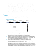
Configuration procedure # Assign each interface an IP address. (Details not shown.) # Configure static routes or a routing protocol to make sure the devices can reach each other. (Details not shown.) # Create an ICMP echo operation and specify 10.2.2.2 as the destination IP address. system-view [DeviceA] nqa entry admin test1 [DeviceA-nqa-admin-test1] type icmp-echo [DeviceA-nqa-admin-test1-icmp-echo] destination ip 10.2.2.2 # Configure 10.1.1.2 as the next hop.
366 3 Succeeded 2007-08-23 15:00:01.2 365 3 Succeeded 2007-08-23 15:00:01.2 364 3 Succeeded 2007-08-23 15:00:01.1 363 2 Succeeded 2007-08-23 15:00:01.1 362 3 Succeeded 2007-08-23 15:00:01.1 361 2 Succeeded 2007-08-23 15:00:01.1 The output shows that the packets sent by Device A can reach Device B through Device C. No packet loss occurs during the operation. The minimum, maximum, and average round-trip times are 2, 5, and 3 milliseconds, respectively.
# Start the UDP echo operation. [DeviceA] nqa schedule admin test1 start-time now lifetime forever # Stop the UDP echo operation after a period of time. [DeviceA] undo nqa schedule admin test1 # Display the results of the UDP echo operation. [DeviceA] display nqa result admin test1 NQA entry (admin admin, tag test1) test results: Send operation times: 1 Receive response times: 1 Min/Max/Average round trip time: 25/25/25 Square-Sum of round trip time: 625 Last succeeded probe time: 2011-11-22 10:36:17.
[SwitchA] ip route-static 10.1.1.2 24 10.2.1.1 track 1 3. On Switch A, configure an NQA operation: # Create an NQA operation with the administrator name being admin and operation tag being test1. [SwitchA] nqa entry admin test1 # Configure the NQA operation type as ICMP echo. [SwitchA-nqa-admin-test1] type icmp-echo # Configure 10.2.1.1 as the destination IP address. [SwitchA-nqa-admin-test1-icmp-echo] destination ip 10.2.1.1 # Configure the operation to repeat at an interval of 100 milliseconds.
127.0.0.1/32 Direct 0 0 127.0.0.1 InLoop0 127.255.255.255/32 Direct 0 0 127.0.0.1 InLoop0 224.0.0.0/4 Direct 0 0 0.0.0.0 NULL0 224.0.0.0/24 Direct 0 0 0.0.0.0 NULL0 255.255.255.255/32 Direct 0 0 127.0.0.1 InLoop0 The output shows that the static route with the next hop 10.2.1.1 is active, and the status of the track entry is positive. # Remove the IP address of VLAN-interface 3 on Switch B.
Configuring sFlow Sampled Flow (sFlow) is a traffic monitoring technology. As shown in Figure 34, the sFlow system involves an sFlow agent embedded in a device and a remote sFlow collector. The sFlow agent collects interface counter information and packet information and encapsulates the sampled information in sFlow packets.
Tasks at a glance Perform at least one of the following tasks: • Configuring flow sampling • Configuring counter sampling Configuring the sFlow agent and sFlow collector information To configure the sFlow agent and sFlow collector information: Step 1. 2. Enter system view. (Optional.) Configure an IP address for the sFlow agent. Command Remarks system-view N/A sflow agent { ip ip-address | ipv6 ipv6-address } By default, no IP address is configured for the sFlow agent.
Step Command Remarks 1. Enter system view. system-view N/A 2. Enter Ethernet interface view. interface interface-type interface-number N/A By default, the device samples packets in random mode. The determine sampling mode is not supported in the current software version. The determine keyword is reserved for future support. 3. (Optional.) Set the flow sampling mode. sflow sampling-mode { determine | random } 4.
Task Command Display sFlow configuration. display sflow sFlow configuration example Network requirements As shown in Figure 35, configure flow sampling in random mode and counter sampling on Ten-GigabitEthernet 1/0/1 of the device to monitor traffic on the port. Configure the device to send sampled information in sFlow packets through Ten-GigabitEthernet 1/0/3 to the sFlow collector. Figure 35 Network diagram Configuration procedure 1.
[Sysname-Ten-GigabitEthernet1/0/1] sflow sampling-rate 4000 # Specify sFlow collector 1 for flow sampling. [Sysname-Ten-GigabitEthernet1/0/1] sflow flow collector 1 Verifying the configurations # Display the sFlow configuration and operation information. [Sysname-Ten-GigabitEthernet1/0/1] display sflow sFlow datagram version: 5 Global information: Agent IP: 3.3.3.1(CLI) Source address: Collector information: ID IP Port Aging Size VPN-instance Description 1 3.3.3.
5.
Monitoring and maintaining processes HP Comware V7 is a full-featured, modular, and scalable network operating system based on the Linux kernel. Comware V7 software features run the following types of independent processes: • User process—Runs in user space. Most Comware V7 software features run user processes. Each process runs in an independent space so the failure of a process does not affect other processes. The system automatically monitors user processes.
Task Command Monitor thread running state. monitor thread [ dumbtty ] [ iteration number ] [ chassis chassis-number slot slot-number ] For detailed information about the display memory [ chassis chassis-number slot slot-number ] command, see Fundamentals Command Reference. Displaying and maintaining user processes Execute display commands in any view. In standalone mode: Task Command Display log information for all user processes.
Configuring kernel thread deadloop detection CAUTION: Inappropriate configuration of kernel thread deadloop detection can cause service problems or system breakdown. Make sure you understand the impact of this configuration on your network before you do it. Kernel threads share resources. If a kernel thread monopolizes the CPU, other threads cannot run, resulting in a deadloop. This feature enables the device to detect deadloops.
Kernel thread starvation detection enables the system to detect and report thread starvation. If a thread is not executed within a specific interval, the system considers that a starvation has occurred, and generates a starvation message. Thread starvation does not impact system operation. A starved thread can automatically run when certain conditions are met. To configure kernel thread starvation detection (in standalone mode): Step Command Remarks 1. Enter system view. system-view N/A 2.
Task Command Display kernel thread starvation detection configuration. display kernel starvation configuration [ slot slot-number ] Clear kernel thread deadloop information. reset kernel deadloop [ slot slot-number ] Clear kernel thread exception information. reset kernel exception [ slot slot-number ] Clear kernel thread reboot information. reset kernel reboot [ slot slot-number ] Clear kernel thread starvation information.
Configuring port mirroring Overview Port mirroring refers to the process of copying the packets passing through a port/CPU to the monitor port connecting to a monitoring device for packet analysis. Terminology The following terms are used in port mirroring configuration. Mirroring source The mirroring source can be one or more monitored ports or CPUs, which are called "source ports," or "source CPUs." Packets passing through them are copied to a port connecting to a monitoring device for packet analysis.
NOTE: • On port mirroring devices, all ports except source, destination, reflector, and egress ports are called common ports. • The reflector port is used to implement the support of local mirroring for multiple monitor ports. Port mirroring classification and implementation Port mirroring includes local port mirroring and remote port mirroring depends on whether the mirroring source and the mirroring destination are on the same device.
• Layer 3 remote port mirroring: The mirroring source and the mirroring destination are separated by IP networks. 1. Layer 2 remote port mirroring The source device copies packets received on the source port to the egress port. The egress port forwards the packets to the intermediate devices, which then broadcast the packets in the remote probe VLAN and transmit the packets to the destination device.
Figure 38 Layer 3 remote port mirroring implementation Source Tunnel interface device XGE1/0/2 Tunnel interface Destination device GRE tunnel IP network XGE1/0/1 XGE1/0/2 XGE1/0/1 Data monitoring device Host Original packets Source port Mirrored packets Common port Monitor port Configuring local port mirroring Local port mirroring takes effect only when the source ports or CPUs, and the monitor port are configured. Local port mirroring configuration task list Tasks at a glance 1. (Required.
• A port can serve as a source port for multiple mirroring groups, but cannot be a reflector port, egress port, or monitor port at the same time. • A Layer 2 aggregate interface cannot be configured as a source port for a mirroring group. Configuration procedure To configure source ports in system view: Step Command Remarks 1. Enter system view. system-view N/A 2. Configure source ports for the specified local mirroring group.
Use a monitor port for port mirroring only to make sure the data monitoring device receives and analyzes only the mirrored traffic rather than a mix of mirrored traffic and normally forwarded traffic. • Configuration procedure To configure the monitor port in system view: Step Command Remarks 1. Enter system view. system-view N/A 2. Configure the monitor port for the specified local mirroring group.
Configuration restrictions and guidelines • The reflector port of a remote source mirroring group must be an access port and belong to the default VLAN, VLAN 1. • HP recommends that you configure an unused port as the reflector port of a remote source mirroring group and disable spanning tree on it. • Do not configure a combo interface as a reflector port. • A mirroring group can contain multiple source ports.
Step Command Remarks 7. Return to system view. quit N/A 8. Configure the remote probe VLAN for the remote source mirroring group. mirroring-group group-id remote-probe vlan rprobe-vlan-id By default, no remote probe VLAN is configured for a mirroring group. Configuring Layer 2 remote port mirroring Configuring Layer 2 remote port mirroring is to configure remote mirroring groups.
Step Create a remote destination group. 2. Command Remarks mirroring-group group-id remote-destination By default, no remote destination group exists on a device. Configuring the monitor port for a remote destination group You can configure the monitor port for a mirroring group in system view, or assign a port to a mirroring group as the monitor port in interface view. The two modes have the same results.
Step Command Remarks 1. Enter system view. system-view N/A 2. Configure the remote probe VLAN for the specified remote destination group. mirroring-group group-id remote-probe vlan vlan-id By default, no remote probe VLAN is configured for a remote destination group. Assigning the monitor port to the remote probe VLAN Step Command Remarks 1. Enter system view. system-view N/A 2. Enter the interface view of the monitor port.
Step Command Remarks 1. Enter system view. system-view N/A 2. Configure source ports for the specified remote source group. mirroring-group group-id mirroring-port interface-list { both | inbound | outbound } By default, no source port is configured for a remote source group. To configure a source port for a remote source group in interface view: Step Command Remarks 1. Enter system view. system-view N/A 2. Enter interface view. interface interface-type interface-number N/A 3.
Step Configure the egress port for the specified remote source group. 2. Command Remarks mirroring-group group-id monitor-egress interface-type interface-number By default, no egress port is configured for a remote source group. To configure the egress port for a remote source group in interface view: Step Command Remarks 1. Enter system view. system-view N/A 2. Enter interface view. interface interface-type interface-number N/A 3.
Layer 3 remote port mirroring configuration task list Tasks at a glance (Required.) Configuring the source device: Configuring local mirroring groups 1. Perform at least one of the following tasks: 2. { { Configuring source ports for a local mirroring group Configuring source CPUs for a local mirroring group Configuring the monitor port for a local mirroring group 3. (Required.) Configuring the destination device: 4. Configuring local mirroring groups 5.
Configuration procedure To configure source ports in system view: Step Command Remarks 1. Enter system view. system-view N/A 2. Configure source ports for the specified local mirroring group. mirroring-group group-id mirroring-port interface-list { both | inbound | outbound } By default, no source port is configured for a local mirroring group. To configure source ports in interface view: Step Command Remarks 1. Enter system view. system-view N/A 2. Enter interface view.
• Do not assign the monitor port to a source VLAN, or enable the spanning tree feature on the monitor port. • HP recommends that you use a monitor port only for port mirroring. This is to make sure the data monitoring device receives and analyzes only the mirrored traffic rather than a mix of mirrored traffic and normally forwarded traffic. Configuration procedure To configure the monitor port in system view: Step Command Remarks 1. Enter system view. system-view N/A 2.
Figure 39 Network diagram Configuration procedure # Create local mirroring group 1. system-view [Device] mirroring-group 1 local # Configure Ten-GigabitEthernet 1/0/1 and Ten-GigabitEthernet 1/0/2 as source ports and port Ten-GigabitEthernet 1/0/3 as the monitor port for local mirroring group 1.
Local port mirroring configuration example (in source CPU mode) Network requirements As shown in Figure 40, Ten-GigabitEthernet 1/0/1 and Ten-GigabitEthernet 1/0/2 are located on the card in slot 1. Configure local port mirroring in source CPU mode to enable the server to monitor all the packets received and sent by the marketing department and the technical department and processed by the CPU of the card in slot 1 of the device.
Mirroring group 1: Type: Local Status: Active Mirroring CPU: Slot 1 Both Monitor port: Ten-GigabitEthernet1/0/3 After the configurations are completed, you can monitor on the server all the packets received and sent by the marketing department and the technical department and processed by the CPU of the card in slot 1 of the device. Local port mirroring with multiple monitor ports configuration example Network requirements As shown in Figure 41, Dept. A, Dept. B, and Dept.
# Configure an unused port (Ten-GigabitEthernet 1/0/5, for example) of Device A as the reflector port of remote source mirroring group 1. [DeviceA] mirroring-group 1 reflector-port ten-gigabitethernet 1/0/5 # Create VLAN 10 and assign the three ports (Ten-GigabitEthernet 1/0/11 through Ten-GigabitEthernet 1/0/13) connecting the three data monitoring devices to VLAN 10.
# Create VLAN 2, which is to be configured as the remote probe VLAN. [DeviceC] vlan 2 # Disable MAC address learning for VLAN 2. [DeviceC-vlan2] undo mac-address mac-learning enable [DeviceC-vlan2] quit # Configure VLAN 2 as the remote probe VLAN of the mirroring group and Ten-GigabitEthernet 1/0/2 as the monitor port of the mirroring group, disable the spanning tree feature on Ten-GigabitEthernet 1/0/2, and assign the port to VLAN 2 as an access port.
[DeviceA] mirroring-group 1 mirroring-port ten-gigabitethernet 1/0/1 both [DeviceA] mirroring-group 1 monitor-egress ten-gigabitethernet 1/0/2 # Configure port Ten-GigabitEthernet 1/0/2 as a trunk port to permit the packets of VLAN 2 to pass through, and disable the spanning tree feature on the port.
Figure 43 Network diagram Configuration procedure 1. Configure IP addresses for the tunnel interfaces and related ports on the devices. (Details not shown.) 2. Configure Device A (the source device): # Create tunnel interface Tunnel 0 that operates in GRE mode, and configure an IP address and subnet mask for the interface. system-view [DeviceA] interface tunnel 0 mode gre [DeviceA-Tunnel0] ip address 50.1.1.1 24 # Configure source and destination IP addresses for Tunnel 0.
[DeviceB-ospf-1] area 0 [DeviceB-ospf-1-area-0.0.0.0] network 20.1.1.0 0.0.0.255 [DeviceB-ospf-1-area-0.0.0.0] network 30.1.1.0 0.0.0.255 [DeviceB-ospf-1-area-0.0.0.0] quit [DeviceB-ospf-1] quit 4. Configure Device C (the destination device): # Create tunnel interface Tunnel 0 that operates in GRE mode, and configure an IP address and subnet mask for the interface. system-view [DeviceC] interface tunnel 0 [DeviceC-Tunnel0] ip address 50.1.1.
Mirroring group 1: Type: Local Status: Active Mirroring port: Ten-GigabitEthernet1/0/1 Inbound Monitor port: Ten-GigabitEthernet1/0/2 After the configurations are completed, you can monitor all the packets received and sent by the marketing department on the server.
Configuring traffic mirroring Overview Local traffic mirroring Local traffic mirroring copies the specified packets to the specified destination for packet analyzing and monitoring. It is implemented through QoS policies. You define traffic classes and configure match criteria to classify packets to be mirrored, and then you configure traffic behaviors to mirror packets that fit the match criteria to the specified destination.
Tasks at a glance (Required.) Applying a QoS policy: • Applying a QoS policy to an interface • Applying a QoS policy to a VLAN • Applying a QoS policy globally Configuring match criteria Step Command Remarks 1. Enter system view. system-view N/A 2. Create a class and enter class view. traffic classifier tcl-name [ operator { and | or } ] By default, no traffic class exists. 3. Configure match criteria. if-match match-criteria By default, no match criterion is configured in a traffic class.
NOTE: After the preceding configuration, you can use the display qos policy command in any view to view QoS policy configuration. Applying a QoS policy Applying a QoS policy to an interface By applying a QoS policy to an interface, you can mirror the traffic in a specified direction on the interface. A policy can be applied to multiple interfaces, but in one direction (inbound or outbound) of an interface, only one policy can be applied. To apply a QoS policy to an interface: Step Command 1.
• Configuring remote source group—Uses the egress port to be the monitor port (port A). For more information, see "Configuring a remote source group on the source device." To prevent packets received or sent by the source port from being mirrored to the destination device through the remote source group, HP recommends that you use an unused interface as the source port of the remote source group.
[DeviceA] acl number 3000 [DeviceA-acl-adv-3000] rule permit tcp source 192.168.2.0 0.0.0.255 destination-port eq www [DeviceA-acl-adv-3000] rule permit ip source 192.168.2.0 0.0.0.255 destination 192.168.1.0 0.0.0.255 time-range work [DeviceA-acl-adv-3000] quit # Create traffic class tech_c, and configure the match criterion as ACL 3000.
Figure 45 Network diagram Configuration procedure 1. Configure Device A: # Configure basic IPv4 ACL 2000 to match packets from the 10.1.1.1/24 network segment. system-view [DeviceA] acl number 2000 [DeviceA-acl-basic-2000] rule permit source 10.1.1.1 255.255.255.0 [DeviceA-acl-basic-2000] quit # Create class 1 and use basic IPv4 ACL 2000 as the match criteria.
[DeviceA] mirroring-group 1 remote-probe vlan 2 [DeviceA] mirroring-group 1 mirroring-port Ten-GigabitEthernet 1/0/48 inbound [DeviceA] mirroring-group 1 monitor-egress Ten-GigabitEthernet 1/0/1 # Configure Ten-GigabitEthernet 1/0/1 as a trunk port and assign it to VLAN 2. [DeviceA] interface Ten-GigabitEthernet 1/0/1 [DeviceA-Ten-GigabitEthernet1/0/1] port link-type trunk [DeviceA-Ten-GigabitEthernet1/0/1] port trunk permit vlan 2 2.
Support and other resources Contacting HP For worldwide technical support information, see the HP support website: http://www.hp.
Conventions This section describes the conventions used in this documentation set. Command conventions Convention Description Boldface Bold text represents commands and keywords that you enter literally as shown. Italic Italic text represents arguments that you replace with actual values. [] Square brackets enclose syntax choices (keywords or arguments) that are optional. { x | y | ... } Braces enclose a set of required syntax choices separated by vertical bars, from which you select one.
Network topology icons Represents a generic network device, such as a router, switch, or firewall. Represents a routing-capable device, such as a router or Layer 3 switch. Represents a generic switch, such as a Layer 2 or Layer 3 switch, or a router that supports Layer 2 forwarding and other Layer 2 features. Represents an access controller, a unified wired-WLAN module, or the switching engine on a unified wired-WLAN switch. Represents an access point.
Index access control MIB, 68 NTP broadcast association authentication, 43 NTP access control rights configuration, 16 NTP client/server association mode, 9, 13, 27 NTP peer ACL, 10 NTP client/server authentication, 41 NTP query ACL, 10 association mode with mode with NTP security, 10 NTP client/server association mode with MPLS VPN time synchronization, 46 NTP server ACL, 10 NTP multicast association mode, 9, 15, 35 NTP synchronization ACL, 10 NTP symmetric active/passive association mode,
IPv6 NTP symmetric active/passive association mode, 31 NTP broadcast server configuration, 15 buffer (output destination), 59 kernel thread deadloop detection, 104 classifying kernel thread starvation detection, 104 port mirroring classification, 108 Layer 2 remote port mirroring, 114, 125 client Layer 3 remote port mirroring, 118, 119, 127 NQA client ICMP echo operation, 84 Layer 3 remote port mirroring local group, 119 NQA client threshold monitoring, 83, 87 Layer 3 remote port mirroring local
remote traffic mirroring on destination device, 134 NTP broadcast association mode, 14, 33 NTP broadcast client, 14 remote traffic mirroring on source device, 133 NTP broadcast mode authentication, 20 sFlow, 96, 99 NTP broadcast mode with authentication, 43 sFlow agent, 97 NTP broadcast server, 15 sFlow collector information, 97 NTP client/server association mode, 13, 27 sFlow counter sampling, 98 NTP client/server mode authentication, 17 sFlow flow sampling, 97 NTP client/server mode with auth
information center synchronous log information output, 61 local traffic mirroring configuration, 131, 134 remote traffic mirroring, 131 IPv6 NTP multicast association mode, 38 traffic mirroring configuration, 131 Layer 2 remote port mirroring, 114 creating Layer 2 remote port mirroring configuration, 114, 125 local port mirroring local group, 110 port mirroring remote destination group, 114 Layer 3 remote port mirroring configuration, 118, 119, 127 port mirroring remote source group, 116 criteria
SNMP settings, 78 port mirroring remote source group source ports, 116 SNTP, 52 remote traffic mirroring configuration, 133 remote traffic mirroring destination device, 134 configuration user processes, 103 on displaying information center, 63 DLSw remote traffic mirroring configuration on source device, 133 NQA, 82 DNS SNMP basic parameter configuration, 69 NQA, 82 SNMP configuration, 68 SNMP MIB, 68 duplicate log suppression, 62 SNMP notification configuration, 75 dynamic NTP max number dyna
default log output rules, 55 flow displaying, 63 sFlow configuration, 96, 99 duplicate log suppression, 62 format link up/down logging disable, 62 system information logs, 55 log output to console, 58, 63 FTP log output to Linux log host, 65 NQA, 82 Get operation (SNMP), 69, 74 log output to log buffer, 59 group log output to log host, 59 log output to monitor terminal, 58 Layer 3 remote port mirroring local group configuration, 119 log output to UNIX log host, 64 Layer 3 remote port mirror
Linux NQA client operation optional parameters, 85 NQA client threshold monitoring, 87 displaying kernel threads, 105 NQA client track collaboration function, 86 kernel thread, 102 NQA client UDP echo operation, 84 kernel thread deadloop detection, 104 NQA configuration, 82, 90 kernel thread starvation detection, 104 NQA history record save, 89 maintaining kernel threads, 105 NQA ICMP echo operation, 90 network maintenance, 102 NQA operation scheduling on NQA client, 89 network monitoring, 102
information center log output to log buffer, 59 NTP client/server association mode, 9 information center log output to log host, 59 NTP multicast association mode, 9 information center log output to monitor terminal, 58 NTP symmetric active/passive association mode, 9 module debugging switch, 5 information center log output to UNIX log host, 64 monitor port information center log save to log file, 60 configuring local port mirroring multiple monitor ports, 124 information center synchronous log in
NTP max number dynamic associations, 25 information center log output to monitor terminal, 58 NTP message receipt disable, 25 information center log output to UNIX log host, 64 NTP message source interface, 24 NTP MPLS VPN support, 11 information center log save to log file, 60 NTP multicast association mode, 15 information center synchronous log information output, 61 NTP multicast mode authentication, 22 IPv6 NTP multicast association mode, 38 NTP optional parameter configuration, 24 Layer 2 re
NTP multicast association mode, 35 traffic mirroring QoS policy application (global), 133 traffic mirroring (interface), 133 QoS policy NTP symmetric active/passive association mode, 29 application ping command, 1 traffic mirroring QoS policy application (VLAN), 133 port mirroring configuration, 107 remote traffic mirroring, 131 traffic mirroring QoS policy configuration, 132 remote traffic mirroring configuration, 133 traffic mirroring traffic behavior configuration, 132 sFlow configuration, 96
client UDP echo operation, 84 configuration, 7, 12 configuration, 82, 90 configuration restrictions, 12 displaying, 90 displaying, 26 history record save, 89 enabling, 12 ICMP echo operation, 90 how it works, 7 operation scheduling on NQA client, 89 IPv6 client/server configuration, 28 statistics collection function, 88 association mode IPv6 multicast association mode configuration, 38 threshold monitoring, 83 track collaboration, 93 track collaboration function, 82 IPv6 symmetric active/pa
NTP message source interface, 24 outbound NTP optional parameter configuration, 24 port mirroring, 107 SNMP basic parameter configuration, 69 outputting information logs to console, 58, 63 SNMPv1 basic parameter configuration, 70 information logs to Linux log host, 65 SNMPv2c basic parameter configuration, 70 information logs to log buffer, 59 SNMPv3 basic parameter configuration, 71 path information logs to log host, 59 NQA path jitter, 82 information logs to monitor terminal, 58 ping command
NTP symmetric active/passive mode with MPLS VPN time synchronization, 47 local mirroring configuration (source port mode), 121 SNTP configuration, 50, 52 mirroring group, 107 monitor port to remote probe VLAN assignment, 116 port mirroring classification, 108 reflector port, 107 configuration, 107 remote, 108 configuring multiple monitor ports, 124 remote destination group configuration, 114 destination, 107 remote destination group creation, 114 direction (bidirectional), 107 remote destinatio
configuring Layer 2 remote port mirroring, 114, 125 configuring NQA statistics collection function, 88 configuring Layer 3 remote port mirroring, 118, 119, 127 configuring NQA track collaboration, 93 configuring NQA UDP echo operation, 92 configuring Layer 3 remote port mirroring local group, 119 configuring NTP, 12 configuring NTP access control rights, 16 configuring Layer 3 remote port mirroring local group source port, 119 configuring NTP association mode, 13 configuring NTP authentication, 16 c
configuring SNMPv3, 80 configuring NTP symmetric active/passive mode with MPLS VPN time synchronization, 47 configuring SNMPv3 agent notification, 76 configuring port mirroring monitor port to remote probe VLAN assignment, 116 configuring SNMPv3 basic parameters, 71 configuring SNTP, 50, 52 configuring port mirroring remote destination group monitor port, 115 configuring SNTP authentication, 51 configuring port mirroring remote destination group on source device, 114 configuring traffic mirroring ma
SNMP versions, 69 maintaining information center, 63 QoS maintaining kernel threads, 105 maintaining processes, 102 local traffic mirroring, 131 monitoring kernel threads, 103 local traffic mirroring configuration, 131, 134 outputting information center logs to console, 58, 63 traffic mirroring configuration, 131 traffic mirroring match criteria configuration, 132 outputting information center logs to Linux log host, 65 traffic mirroring QoS policy application, 133 outputting information center lo
IPv6 NTP symmetric active/passive association mode, 31 remote destination group configuration, 114 remote destination group creation, 114 remote destination configuration, 115 group monitor NTP association mode, 13 port NTP broadcast association mode, 33 NTP broadcast mode with authentication, 43 remote destination group remote probe VLAN configuration, 115 NTP client/server association mode, 27 remote source group egress port, 117 NTP client/server mode with authentication, 41 remote source grou
NTP symmetric authentication, 18 active/passive notification enable, 75 mode Notification operation, 69 SNTP authentication, 51 NQA, 82 server protocol versions, 69 NTP broadcast client configuration, 14 Set operation, 69, 74 NTP broadcast server configuration, 15 SNMPv1 basic parameter configuration, 70 NTP multicast server configuration, 15 SNMPv1 configuration, 78 SNTP configuration, 50, 52 SNMPv2c basic parameter configuration, 70 Set operation (SNMP), 69, 74 SNMPv2c configuration, 78
using tracert to identify node failures, 4 NTP server specification, 50 system information source common information logs, 54 port mirroring, 107 default log output rules, 55 specifying NTP message source interface, 24 diagnostic information logs, 54 NTP server for SNTP, 50 duplicate log suppression, 62 starvation detection (Linux kernel thread), 104 format, 55 statistics hidden information logs, 54 NQA statistics collection function, 88 information center configuration, 54, 57 sFlow agent
NQA operation threshold triggered action none, 87 NTP configuration, 7, 12 NTP local clock as reference source, 26 NQA operation threshold triggered action trap-only, 87 SNTP configuration, 50, 52 tracert command NQA operation threshold triggered action trigger-only, 87 IP address retrieval, 3, 4 node failure detection, 3, 4 troubleshooting track sFlow, 100 NQA client track collaboration function, 86 sFlow remote collector cannot receive packets, 100 NQA collaboration, 82 UDP NQA track collabora
system debugging, 1 local port mirroring group source port, 110 tracert, 1, 4 local traffic mirroring configuration, 131, 134 tracert to identify node failures, 4 port mirroring configuration, 107 view-based MIB access control, 68 port mirroring remote probe VLAN, 107 VLAN traffic mirroring configuration, 131 traffic mirroring QoS policy application, 133 enabling port mirroring multiple monitor ports (remote probe VLAN), 112 voice Layer 2 remote port mirroring, 114 NQA, 82 Layer 2 remote port