
R21xx-HP FlexFabric 11900 Network Management and Monitoring Configuration Guide


109
• Layer 3 remote port mirroring: The mirroring source and the mirroring destination are separated by
IP networks.
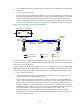
1. Layer 2 remote port mirroring
The source device copies packets received on the source port to the egress port. The egress port
forwards the packets to the intermediate devices, which then broadcast the packets in the remote
probe VLAN and transmit the packets to the destination device. Upon receiving the mirrored
packets, the destination device checks whether their VLAN IDs are the same as the remote probe
VLAN ID. If yes, the device forwards them to the data monitoring device through the monitor port.
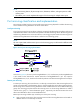
Figure 37 Layer 2 remote port mirroring implementation
To make sure the source device and the destination device can communicate at Layer 2 through the
remote probe VLAN, assign the intermediate devices' ports in the direction to the source and destination
devices to the remote probe VLAN.
To monitor both the received and sent packets of a port in a mirroring group, you must disable MAC
address learning for the remote probe VLAN on the source, intermediate, and destination devices. For
more information about MAC address learning, see Layer 2 — LAN Switching Configuration Guide.
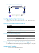
2. Layer 3 remote port mirroring
Layer 3 remote port mirroring is implemented through creating a local mirroring group on the
source device and one on the destination device.
The source device sends one copy of packets received on the source port Ten-GigabitEthernet
1/0/1 to the tunnel interface (serving as the monitor port in the local mirroring group created on
the source device), which then forwards them to the tunnel interface on the destination device
through the GRE tunnel. The destination device receives the mirrored packets from the physical
interface (serving as the source port in the local mirroring group created on the destination device)
of the tunnel interface, and then sends one copy of the packets to the monitor port
Ten-GigabitEthernet 1/0/2. Ten-GigabitEthernet 1/0/2 forwards the packets to the data
monitoring device. For more information about GRE tunnels and tunnel interfaces, see Layer 3—IP
Services Configuration Guide.
Destination
device
Source
device
Intermediate
device
XGE1/0/1
Remote
probe VLAN
Data monitoring
device
Host
Remote
probe VLAN
XGE1/0/2 XGE1/0/1 XGE1/0/2 XGE1/0/1
XGE1/0/2
XGE1/0/1
Mirroring process in the device
XGE1/0/2
Source port
Monitor port
Original packets
Common portMirrored packets
Egress port