
R21xx-HP FlexFabric 11900 Network Management and Monitoring Configuration Guide


125
# Configure an unused port (Ten-GigabitEthernet 1/0/5, for example) of Device A as the reflector port
of remote source mirroring group 1.
[DeviceA] mirroring-group 1 reflector-port ten-gigabitethernet 1/0/5
# Create VLAN 10 and assign the three ports (Ten-GigabitEthernet 1/0/11 through Ten-GigabitEthernet
1/0/13) connecting the three data monitoring devices to VLAN 10.
[DeviceA] vlan 10
[DeviceA-vlan10] port ten-gigabitethernet 1/0/11 to ten-gigabitethernet 1/0/13
[DeviceA-vlan10] quit
# Configure VLAN 10 as the remote probe VLAN of remote source mirroring group 1.
[DeviceA] mirroring-group 1 remote-probe vlan 10
Layer 2 remote port mirroring configuration
example
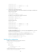
Network requirements
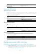
On the Layer 2 network shown in Figure 42, configure Layer 2 remote port mirroring to enable the server
to monitor the bidirectional traffic of the marketing department.
Figure 42 Network diagram
Configuration procedure
1. Configure Device C (the destination device):
# Configure Ten-GigabitEthernet 1/0/1 as a trunk port to permit the packets of VLAN 2 to pass
through.
<DeviceC> system-view
[DeviceC] interface ten-gigabitethernet 1/0/1
[DeviceC-Ten-GigabitEthernet1/0/1] port link-type trunk
[DeviceC-Ten-GigabitEthernet1/0/1] port trunk permit vlan 2
[DeviceC-Ten-GigabitEthernet1/0/1] quit
# Create a remote destination group.
[DeviceC] mirroring-group 2 remote-destination