
R21xx-HP FlexFabric 11900 Network Management and Monitoring Configuration Guide


128
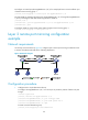
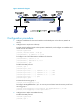
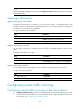
Figure 43 Network diagram
Configuration procedure
1. Configure IP addresses for the tunnel interfaces and related ports on the devices. (Details not
shown.)
2. Configure Device A (the source device):
# Create tunnel interface Tunnel 0 that operates in GRE mode, and configure an IP address and
subnet mask for the interface.
<DeviceA> system-view
[DeviceA] interface tunnel 0 mode gre
[DeviceA-Tunnel0] ip address 50.1.1.1 24
# Configure source and destination IP addresses for Tunnel 0.
[DeviceA-Tunnel0] source 20.1.1.1
[DeviceA-Tunnel0] destination 30.1.1.2
[DeviceA-Tunnel0] quit
# Enable the OSPF protocol.
[DeviceA] ospf 1
[DeviceA-ospf-1] area 0
[DeviceA-ospf-1-area-0.0.0.0] network 10.1.1.0 0.0.0.255
[DeviceA-ospf-1-area-0.0.0.0] network 20.1.1.0 0.0.0.255
[DeviceA-ospf-1-area-0.0.0.0] network 50.1.1.0 0.0.0.255
[DeviceA-ospf-1-area-0.0.0.0] quit
[DeviceA-ospf-1] quit
# Create local mirroring group 1.
[DeviceA] mirroring-group 1 local
# Configure Ten-GigabitEthernet 1/0/1 as a source port and Tunnel 0 as the monitor port of local
mirroring group 1.
[DeviceA] mirroring-group 1 mirroring-port ten-gigabitethernet 1/0/1 both
[DeviceA] mirroring-group 1 monitor-port tunnel 0
3. Configure Device B (the intermediate device):
# Enable the OSPF protocol.
<DeviceB> system-view
[DeviceB] ospf 1