
R21xx-HP FlexFabric 11900 Network Management and Monitoring Configuration Guide

27
NTP client/server mode configuration example
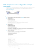
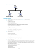
Network requirements
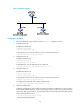
As shown in Figure 9, the local clock of Device A is to be used as a reference source, with the stratum level
2. Device B operates in client mode and Device A is to be used as the NTP server for Device B.
Figure 9 Network diagram
Configuration procedure
1. Set the IP address for each interface as shown in Figure 9. (Details not shown.)
2. Configure Device A:
# Enable the NTP service.
<DeviceA> system-view
[DeviceA] ntp-service enable
# Specify the local clock as the reference source, with the stratum level 2.
[DeviceA] ntp-service refclock-master 2
3. Configure Device B:
# Enable the NTP service.
<DeviceB> system-view
[DeviceB] ntp-service enable
# Specify Device A as the NTP server of Device B so that Device B is synchronized to Device A.
[DeviceB] ntp-service unicast-server 1.0.1.11
4. Verify the configuration:
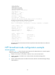
# Display the NTP status of Device B after clock synchronization.
[DeviceB] display ntp-service status
Clock status: synchronized
Clock stratum: 3
System peer: 1.0.1.11
Local mode: client
Reference clock ID: 1.0.1.11
Leap indicator: 00
Clock jitter: 0.000977 s
Stability: 0.000 pps
Clock precision: 2^-10
Root delay: 0.00383 ms
Root dispersion: 16.26572 ms
Reference time: d0c6033f.b9923965 Wed, Dec 29 2010 18:58:07.724
The output shows that Device B has been synchronized to Device A, the clock stratum level of
Device B is 3, and that of Device A is 2.
# Display IPv4 NTP association information for Device B.
[DeviceB] display ntp-service sessions