
R21xx-HP FlexFabric 11900 Network Management and Monitoring Configuration Guide

28
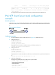
source reference stra reach poll now offset delay disper
********************************************************************************
[12345]1.0.1.11 127.127.1.0 2 1 64 15 -4.0 0.0038 16.262
Notes: 1 source(master), 2 source(peer), 3 selected, 4 candidate, 5 configured.
Total sessions : 1
The output shows that an association has been set up between Device B and Device A.
IPv6 NTP client/server mode configuration
example
Network requirements
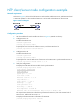
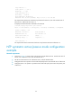
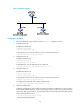
As shown in Figure 10, the local clock of Device A is to be used as a reference source, with the stratum
level 2. Device B operates in client mode and Device A is to be used as the IPv6 NTP server for Device
B.
Figure 10 Network diagram
Configuration procedure
1. Set the IP address for each interface as shown in Figure 10. (Details not shown.)
2. Configure Device A:
# Enable the NTP service.
<DeviceA> system-view
[DeviceA] ntp-service enable
# Specify the local clock as the reference source, with the stratum level 2.
[DeviceA] ntp-service refclock-master 2
3. Configure Device B:
# Enable the NTP service.
<DeviceB> system-view
[DeviceB] ntp-service enable
# Specify Device A as the IPv6 NTP server of Device B so that Device B is synchronized to Device
A.
[DeviceB] ntp-service ipv6 unicast-server 3000::34
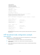
4. Verify the configuration:
# Display the NTP status of Device B after clock synchronization.
[DeviceB] display ntp-service status
Clock status: synchronized
Clock stratum: 3
System peer: 3000::34
Local mode: client
Reference clock ID: 163.29.247.19