HP FlexFabric 11900 Switch Series Security Configuration Guide Part number: 5998-4065 Software version: Release 2105 and later Document version: 6W100-20130515
Legal and notice information © Copyright 2013 Hewlett-Packard Development Company, L.P. No part of this documentation may be reproduced or transmitted in any form or by any means without prior written consent of Hewlett-Packard Development Company, L.P. The information contained herein is subject to change without notice.
Contents Configuring AAA ························································································································································· 1 Overview············································································································································································ 1 RADIUS ·············································································································································
Enabling password control ··········································································································································· 60 Setting global password control parameters ·············································································································· 61 Setting user group password control parameters ······································································································· 62 Setting local user password cont
Working with SFTP files ········································································································································ 89 Displaying help information ································································································································· 89 Terminating the connection with the SFTP server ······························································································· 89 Configuring the device as an SCP client
Configuring ARP packet validity check ············································································································· 132 Configuring ARP restricted forwarding ············································································································· 133 Displaying and maintaining ARP detection ······································································································ 133 User validity check and ARP packet validity check configurat
Applying an IPsec policy to an interface ·········································································································· 165 Enabling ACL checking for de-encapsulated packets······················································································ 165 Configuring the IPsec anti-replay function ········································································································ 166 Binding a source interface to an IPsec policy ······················
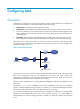
Configuring AAA Overview Authentication, Authorization, and Accounting (AAA) provides a uniform framework for implementing network access management. It specifies the following security functions: • Authentication—Identifies users and verifies their validity. • Authorization—Grants different users different rights and controls their access to resources and services.
The device performs dynamic password authentication. RADIUS Remote Authentication Dial-In User Service (RADIUS) is a distributed information interaction protocol that uses a client/server model. It can protect networks against unauthorized access and is often used in network environments that require both high security and remote user access. The RADIUS authorization process is combined with the RADIUS authentication process, and user authorization information is piggybacked in authentication responses.
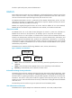
Basic RADIUS packet exchange process Figure 3 illustrates the interactions between a user host, the RADIUS client, and the RADIUS server. Figure 3 Basic RADIUS packet exchange process RADIUS operates in the following manner: 1. The host sends a connection request that carries the user's username and password to the RADIUS client. 2.
RADIUS packet format RADIUS uses UDP to transmit packets. To ensure smooth packet exchange between the RADIUS server and the client, RADIUS uses a series of mechanisms, including the timer mechanism, the retransmission mechanism, and the backup server mechanism. Figure 4 shows the RADIUS packet format. Figure 4 RADIUS packet format Descriptions of the fields are as follows: The Code field (1 byte long) indicates the type of the RADIUS packet. Table 1 gives the main values and their meanings.
• The Authenticator field (16 bytes long) is used to authenticate responses from the RADIUS server and to encrypt user passwords. There are two types of authenticators: request authenticator and response authenticator. • The Attributes field (variable in length) carries specific authentication, authorization, and accounting information. This field can contain multiple attributes, each with three sub-fields: { Type—Type of the attribute.
No. Attribute No.
Figure 5 Format of attribute 26 HWTACACS HW Terminal Access Controller Access Control System (HWTACACS) is an enhanced security protocol based on TACACS (RFC 1492). Similar to RADIUS, it uses a client/server model for information exchange between the NAS and the HWTACACS server. HWTACACS typically provides AAA services for PPP, VPDN, and terminal users. In a typical HWTACACS scenario, some terminal users need to log in to the NAS for operations.
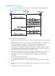
Figure 6 Basic HWTACACS packet exchange process for a Telnet user Host HWTACACS client HWTACACS server 1) The user tries to log in 2) Start-authentication packet 3) Authentication response requesting the username 4) Request for username 5) The user enters the username 6) Continue-authentication packet with the username 7) Authentication response requesting the password 8) Request for password 9) The user enters the password 10) Continue-authentication packet with the password 11) Response indicating succ
9. The user enters the password. 10. After receiving the login password, the HWTACACS client sends the HWTACACS server a continue-authentication packet that carries the login password. 11. If the authentication succeeds, the HWTACACS server sends back an authentication response to indicate that the user has passed authentication. 12. The HWTACACS client sends a user authorization request packet to the HWTACACS server. 13.
1. An LDAP client uses the LDAP server administrator DN to bind with the LDAP server, establishes a connection to the server, and obtains the search rights. 2. The LDAP client uses the username in the authentication information of a user to construct search conditions, searches for the user in the specified root directory of the server, and obtains a user DN list. 3. The LDAP client uses each user DN in the obtained user DN list and the user's password to bind with the LDAP server.
4. The LDAP server processes the request. If the bind operation is successful, the LDAP server sends an acknowledgement to the LDAP client. 5. The LDAP client sends a user DN search request with the username of the Telnet user to the LDAP server. 6. After receiving the request, the LDAP server searches for the user DN by the base DN, search scope, and filtering conditions. If a match is found, the LDAP server sends a response to notify the LDAP client of the successful search.
AAA also supports configuring a set of default methods for an ISP domain. These default methods are used for users for whom no specific AAA methods are configured. The device supports the following authentication methods: • No authentication—This method trusts all users and does not perform authentication. For security purposes, do not use this method.
AAA for MPLS L3VPNs In an MPLS L3VPN scenario where clients in different VPNs are centrally authenticated, you can deploy AAA across VPNs to enable forwarding of RADIUS and HWTACACS packets across MPLS VPNs. For example, in the network shown in Figure 9, you can deploy the AAA across VPNs feature, so that the PE at the left side of the MPLS backbone serves as a NAS and transparently delivers the AAA packets of private users in VPN 1 and VPN 2 to the AAA servers in VPN 3 for centralized authentication.
No. Attribute Description 4 NAS-IP-Address IP address for the server to use to identify the client. Usually, a client is identified by the IP address of its access interface. This attribute is only present in Access-Request packets. 5 NAS-Port Physical port of the NAS that the user accesses. 6 Service-Type Type of service that the user has requested or type of service to be provided. 7 Framed-Protocol Encapsulation protocol for framed access.
No. Attribute Description Type of the physical port of the NAS that is authenticating the user. Possible values include: • 15—Ethernet. • 16—Any type of ADSL. 61 NAS-Port-Type • 17—Cable. (With cable for cable TV.) • 19—WLAN-IEEE 802.11. • 201—VLAN. • 202—ATM. If the port is an ATM or Ethernet one and VLANs are implemented on it, the value of this attribute is 201. 79 EAP-Message Used to encapsulate EAP packets to allow RADIUS to support EAP authentication.
No. Sub-attribute Description 25 Result_Code Result of the Trigger-Request or SetPolicy operation, zero for success and any other value for failure. 26 Connect_ID Index of the user connection. 28 Ftp_Directory FTP user working directory. When the RADIUS client acts as the FTP server, this attribute is used to set the FTP directory for an FTP user on the RADIUS client. 29 Exec_Privilege EXEC user priority.
1. Configure the required AAA schemes. { { 2. Local authentication—Configure local users and the related attributes, including the usernames and passwords, for the users to be authenticated. Remote authentication—Configure the required RADIUS, HWTACACS, and LDAP schemes. Configure AAA methods for the users' ISP domains. Remote AAA methods need to reference the configured RADIUS, HWTACACS, and LDAP schemes.
Configuring AAA schemes This section includes information on configuring local users, RADIUS schemes, HWTACACS schemes, and LDAP schemes. Configuring local users To implement local authentication, authorization, and accounting, create local users and configure user attributes on the device. The local users and attributes are stored in the local user database on the device. A local user is uniquely identified by the combination of a username and a user type.
information about password management and global password configuration, see "Configuring password control." Local user configuration task list Tasks at a glance (Required.) Configuring local user attributes (Optional.) Configuring user group attributes (Optional.
Step Command Remarks • In non-FIPS mode: 4. Assign services for the local user. service-type { ftp | { ssh | telnet | terminal } * } • In FIPS mode: By default, no service is authorized to a local user. service-type { ssh | terminal } * 5. 6. (Optional.) Place the local user to the active or blocked state. (Optional.) Configure authorization attributes for the local user.
Step 3. Configure authorization attributes for the user group. Command Remarks authorization-attribute { acl acl-number | idle-cut minute | vlan vlan-id | work-directory directory-name } * By default, no authorization attribute is configured for a user group. • Set the password aging time: password-control aging aging-time 4. (Optional.) Configure password control attributes for the user group.
Tasks at a glance (Optional.) Specifying the source IP address for outgoing RADIUS packets (Optional.) Setting RADIUS timers (Optional.) Configuring the accounting-on feature (Optional.) Configuring the IP addresses of the security policy servers (Optional.) Displaying and maintaining RADIUS Creating a RADIUS scheme Create a RADIUS scheme before performing any other RADIUS configurations. You can configure up to 16 RADIUS schemes. A RADIUS scheme can be referenced by multiple ISP domains.
Step Command Remarks • Specify the primary RADIUS 3. Specify RADIUS authentication servers. authentication server: primary authentication { ipv4-address | ipv6 ipv6-address } [ port-number | key { cipher | simple } string | vpn-instance vpn-instance-name ] * • Specify a secondary RADIUS authentication server: secondary authentication { ipv4-address | ipv6 ipv6-address } [ port-number | key { cipher | simple } string | vpn-instance vpn-instance-name ] * Configure at least one command.
Specifying the shared keys for secure RADIUS communication The RADIUS client and server use the MD5 algorithm and shared keys to generate the Authenticator value for packet authentication and user password encryption. They must use the same key for each type of communication. A key configured in this task is for all servers of the same type (accounting or authentication) in the scheme, and has a lower priority than a key configured individually for a RADIUS server.
Step Command Remarks N/A 2. Enter RADIUS scheme view. radius scheme radius-scheme-name 3. Set the format for usernames sent to the RADIUS servers. user-name-format { keep-original | with-domain | without-domain } 4. Set the data flow and packet measurement units for traffic statistics. data-flow-format { data { byte | giga-byte | kilo-byte | mega-byte } | packet { giga-packet | kilo-packet | mega-packet | one-packet } }* Optional. By default, the ISP domain name is included in a username.
If no server is found reachable during one search process, the device considers the authentication or accounting attempt a failure. • If you remove an authentication or accounting server in use, the communication of the device with the server soon times out, and the device looks for a server in active state by first checking the primary server and then secondary servers in the order they are configured.
address. For example, if the NAS is configured with VRRP for stateful failover, the source IP address of outgoing RADIUS packets can be the virtual IP address of the uplink VRRP group. You can specify a source IP address for outgoing RADIUS packets in RADIUS scheme view for a specific RADIUS scheme, or in system view for all RADIUS schemes whose servers are in a VPN or the public network. Before sending a RADIUS packet, the NAS selects a source IP address in the following order: 1.
• When you configure the maximum number of RADIUS packet transmission attempts and the RADIUS server response timeout timer, consider the number of secondary servers. If the retransmission process takes too much time, the client connection in the access module such as the Telnet module might time out while the device is trying to find an available server.
Configuring the IP addresses of the security policy servers The NAS verifies the validity of received control packets and accepts only control packets from known servers. To use a security policy server that is independent of the AAA servers, configure the IP address of the security policy server on the NAS. The security policy server is the management and control center of the HP EAD solution.
Tasks at a glance (Optional.) Displaying and maintaining HWTACACS Creating an HWTACACS scheme Create an HWTACACS scheme before performing any other HWTACACS configurations. You can configure up to 16 HWTACACS schemes. An HWTACACS scheme can be referenced by multiple ISP domains. To create an HWTACACS scheme: Step Command Remarks 1. Enter system view. system-view N/A 2. Create an HWTACACS scheme and enter its view. hwtacacs scheme hwtacacs-scheme-name By default, no HWTACACS scheme is defined.
function as the primary authorization server of one scheme and as the secondary authorization server of another scheme at the same time. To specify HWTACACS authorization servers for an HWTACACS scheme: Step Command Remarks 1. Enter system view. system-view N/A 2. Enter HWTACACS scheme view. hwtacacs scheme hwtacacs-scheme-name N/A • Specify the primary HWTACACS 3. Specify HWTACACS authorization servers.
Step Command Remarks • Specify the primary HWTACACS 3. Specify HWTACACS accounting servers. accounting server: primary accounting { ipv4-address | ipv6 ipv6-address } [ port-number | key { cipher | simple } string | vpn-instance vpn-instance-name ] * • Specify a secondary HWTACACS accounting server: secondary accounting { ipv4-address | ipv6 ipv6-address } [ port-number | key { cipher | simple } string | vpn-instance vpn-instance-name ] * Configure at least one command.
Setting the username format and traffic statistics units A username is usually in the format userid@isp-name, where isp-name represents the user's ISP domain name. By default, the ISP domain name is included in a username. However, some HWTACACS servers do not recognize usernames that contain ISP domain names. In this case, you can configure the device to remove the domain name from each username to be sent.
Step Command Remarks 1. Enter system view. system-view N/A 2. Specify a source IP address for outgoing HWTACACS packets. hwtacacs nas-ip { ipv4-address | ipv6 ipv6-address } [ vpn-instance vpn-instance-name ] By default, the IP address of the HWTACACS packet outbound interface is used as the source IP address. To specify a source IP address for a specific HWTACACS scheme: Step Command Remarks 1. Enter system view. system-view N/A 2. Enter HWTACACS scheme view.
Step 4. Set the server quiet timer. Command Remarks timer quiet minutes By default, the server quiet timer is 5 minutes. By default, the real-time accounting interval is 12 minutes. 5. Set the real-time accounting interval. timer realtime-accounting minutes Consider the performance of the NAS and the HWTACACS server when you set the real-time accounting interval. A short interval helps improve accounting precision but requires many system resources.
Step 2. Create an LDAP server and enter its view. Command Remarks ldap server server-name By default, no LDAP server exists. Configuring the IP address of the LDAP server Step Command Remarks 1. Enter system view. System-view N/A 2. Enter LDAP server view. ldap server server-name N/A 3. Configure the IP address of the LDAP server. { ip ip-address | ipv6 ipv6-address } [ port port-number ] [ vpn-instance vpn-instance-name ] By default, an LDAP server has no IP address.
Configuring administrator attributes To configure the administrator DN and password for binding with the LDAP server during LDAP authentication: Step Command Remarks 1. Enter system view. system-view N/A 2. Enter LDAP server view. ldap server server-name N/A By default, no administrator DN is specified. 3. Specify the administrator DN. login-dn dn-string The administrator DN specified on the device must be consistent with the administrator DN specified on the LDAP server. 4.
Step 7. (Optional.) Specify the user object class. Command Remarks user-parameters user-object-class object-class-name By default, no user object is specified, and the default user object class on the LDAP server is used. Creating an LDAP scheme You can configure up to 16 LDAP schemes. An LDAP scheme can be referenced by multiple ISP domains. To create an LDAP scheme: Step Command Remarks 1. Enter system view. system-view N/A 2. Create an LDAP scheme and enter its view.
Creating an ISP domain In a networking scenario with multiple ISPs, the device can connect to users of different ISPs, and these users can have different user attributes, such as different username and password structures, different service types, and different rights. To manage users of different ISPs, configure ISP domains, and configure AAA methods and domain attributes for each ISP domain as needed. The device supports up to 16 ISP domains, including the system predefined ISP domain system.
Configuring authentication methods for an ISP domain Configuration prerequisites Before configuring authentication methods, complete the following tasks: 1. For RADIUS, HWTACACS, or LDAP authentication, configure the RADIUS, HWTACACS, or LDAP scheme to be referenced first. The local and none authentication methods do not require a scheme. 2. Determine the access type or service type to be configured. With AAA, you can configure an authentication method for each access type and service type. 3.
Configuring authorization methods for an ISP domain Configuration prerequisites Before configuring authorization methods, complete the following tasks: 1. For HWTACACS authorization, configure the HWTACACS scheme to be referenced. 2. Determine the access type or service type to be configured. With AAA, you can configure an authorization scheme for each access type and service type. 3. Determine whether to configure the default authorization method for all access types or service types.
Configuring accounting methods for an ISP domain Configuration prerequisites Before configuring accounting methods, complete the following tasks: 1. For RADIUS or HWTACACS accounting, configure the RADIUS or HWTACACS scheme to be referenced first. The local and none accounting methods do not require a scheme. 2. Determine the access type or service type to be configured. With AAA, you can configure an accounting method for each access type and service type. 3.
To enable the session-control feature: Step Command Remarks 1. Enter system view. system-view N/A 2. Enable the session-control feature. radius session-control enable By default, the session-control feature is disabled.
Figure 11 Network diagram Configuration procedure 1. Configure the HWTACACS server: # On the HWTACACS server, set the shared keys for secure communication with the switch to expert, add an account for the SSH user, and specify the password. (Details not shown.) 2. Configure the switch: # Assign IP addresses to the interfaces. (Details not shown.) # Create an HWTACACS scheme. system-view [Switch] hwtacacs scheme hwtac # Specify the primary authentication server.
# Enable the default user role feature to assign authenticated SSH users the default user role network-operator. [Switch] role default-role enable 3. Verify the configuration: When the user initiates an SSH connection to the switch and enter the correct username and password, the user successfully logs in and can use the commands for the network-operator user role. AAA configuration examples Unless otherwise noted, devices in the configuration examples are operating in non-FIPS mode.
# Configure an HWTACACS scheme. [Switch] hwtacacs scheme hwtac [Switch-hwtacacs-hwtac] primary authorization 10.1.1.2 49 [Switch-hwtacacs-hwtac] key authorization simple expert [Switch-hwtacacs-hwtac] user-name-format without-domain [Switch-hwtacacs-hwtac] quit # Configure a RADIUS scheme. [Switch] radius scheme rd [Switch-radius-rd] primary accounting 10.1.1.
Figure 13 Network diagram Configuration procedure 1. Configure the RADIUS server on IMC 5.0: NOTE: This example assumes that the RADIUS server runs on IMC PLAT 5.0 (E0101) and IMC UAM 5.0 (E0101). # Add the switch to the IMC Platform as an access device. Log in to IMC, click the Service tab, and select User Access Manager > Access Device Management > Access Device from the navigation tree. Then, click Add to configure an access device as follows: a.
Figure 14 Adding the switch as an access device # Add an account for device management. Click the User tab, and select Access User View > Device Mgmt User from the navigation tree. Then, click Add to configure a device management account as follows: a. Enter the account name hello@bbb and specify the password. b. Select the service type SSH. c. Specify 10.1.1.0 to 10.1.1.255 as the IP address range of the hosts to be managed. d. Click OK.
Figure 15 Adding an account for device management 2. Configure the switch: # Assign an IP address to VLAN-interface 2, the SSH user access interface. system-view [Switch] interface vlan-interface 2 [Switch-Vlan-interface2] ip address 192.168.1.70 255.255.255.0 [Switch-Vlan-interface2] quit # Assign an IP address to VLAN-interface 3, through which the switch communicates with the server. [Switch] interface vlan-interface 3 [Switch-Vlan-interface3] ip address 10.1.1.2 255.255.255.
[Switch-radius-rad] key authentication simple expert # Include the domain names in usernames sent to the RADIUS server. [Switch-radius-rad] user-name-format with-domain [Switch-radius-rad] quit # Create ISP domain bbb and configure authentication and authorization methods for login users. [Switch] domain bbb [Switch-isp-bbb] authentication login radius-scheme rad [Switch-isp-bbb] authorization login radius-scheme rad [Switch-isp-bbb] quit 3.
Figure 17 Adding user aaa d. In the pop-up dialog box, enter the password ldap!123456, select options as needed, and click Next. Figure 18 Setting the user's password # Add user aaa to group Users. a. From the navigation tree, click Users under the ldap.com node. b. On the right pane, right-click aaa and select Properties. c. From the pop-up dialog box, click the Member Of tab and then select Domain Users and click Add.
Figure 19 Modifying user properties d. In the pop-up Select Groups dialog box, click OK to add user aaa to group Users. Figure 20 Adding user aaa to group Users # Set the administrator password to admin!123456. a. From the user list on the right pane, right-click Administrator and select Set Password. b. In the pop-up dialog box, enter the administrator password. (Details not shown.) 2. Configure the switch: # Assign an IP address to VLAN-interface 2, the SSH user access interface.
[Switch] interface vlan-interface 2 [Switch-Vlan-interface2] ip address 192.168.1.70 24 [Switch-Vlan-interface2] quit # Assign an IP address to VLAN-interface 3, through which the switch communicates with the server. [Switch] interface vlan-interface 3 [Switch-Vlan-interface3] ip address 10.1.1.2 24 [Switch-Vlan-interface3] quit # Create local RSA and DSA key pairs. [Switch] public-key local create rsa [Switch] public-key local create dsa # Enable the SSH service.
Troubleshooting RADIUS RADIUS authentication failure Symptom User authentication always fails. Analysis Possible reasons include: • A communication failure exists between the NAS and the RADIUS server. • The username is not in the format userid@isp-name, or the ISP domain is not correctly configured on the NAS. • The user is not configured on the RADIUS server. • The password entered by the user is incorrect. • The RADIUS server and the NAS are configured with different shared keys.
• The authentication and accounting UDP port numbers configured on the NAS are the same as those of the RADIUS server. • The RADIUS server's authentication and accounting port numbers are available. RADIUS accounting error Symptom A user is authenticated and authorized, but accounting for the user is not normal. Analysis The accounting server configuration on the NAS is not correct. Possible reasons include: • The accounting port number configured on the NAS is incorrect.
• The NAS and the LDAP server can ping each other. • The IP address and port number of the LDAP server configured on the NAS match those of the server. • The username is in the correct format and the ISP domain for the user authentication is correctly configured on the NAS. • The user is configured on the LDAP server. • The correct password is entered. • The administrator DN and the administrator password are correctly configured.
Configuring password control Overview Password control refers to a set of functions provided by the device to manage login and super password setup, expirations, and updates for device management users, and to control user login status based on predefined policies. NOTE: • Local users are divided into two types: device management users and network access users. This feature applies only to device management users. For more information about local users, see "Configuring AAA.
Password complexity checking policy A less complicated password such as a password containing the username or repeated characters is more likely to be cracked. For higher security, you can configure a password complexity checking policy to make sure all user passwords are relatively complicated. With such a policy configured, when a user configures a password, the system checks the complexity of the password. If the password is complexity-incompliant, the configuration will fail.
Password history With this feature enabled, the system stores passwords that a user has used. When a user changes the password, the system checks the new password against the current password and those stored in the password history records. The new password must be different from the current one and those stored in the history records by at least four characters and the four characters must be different from one another.
Logging The system logs all successful password changing events and user adding events to the password control blacklist. FIPS compliance The device supports the FIPS mode that complies with NIST FIPS 140-2 requirements. Support for features, commands, and parameters might differ in FIPS mode (see "Configuring FIPS") and non-FIPS mode. Password control configuration task list The password control functions can be configured in several different views, and different views support different functions.
Step Command Remarks 1. Enter system view. system-view N/A 2. Enable the global password control feature. password-control enable By default, the global password control feature is disabled. 3. (Optional.) Enable a specific password control function. password-control { aging | composition | history | length } enable By default, all four password control functions are enabled.
Step Command Remarks 8. Specify the maximum number of login attempts and the action to be taken when a user fails to log in after the specified number of attempts. password-control login-attempt login-times [ exceed { lock | lock-time time | unlock } ] By default, the maximum number of login attempts is 3 and a user failing to log in after the specified number of attempts must wait for 1 minute before trying again. 9.
Step Command Remarks By default, no local user exists. 2. Create a device management user and enter local user view. local-user user-name class manage Local user password control applies to device management users instead of network access users. For information about how to configure a local user, see "Configuring AAA." 3. 4. 5. Configure the password expiration time for the local user. Configure the minimum password length for the local user.
Displaying and maintaining password control Execute display commands in any view and reset commands in user view. Task Command Display password control configuration. display password-control [ super ] Display information about users in the password control blacklist. display password-control blacklist [ user-name name | ip ipv4-address | ipv6 ipv6-address ] Delete users from the password control blacklist. reset password-control blacklist [ user-name name ] Clear history password records.
# Prohibit the user from logging in forever after two successive login failures. [Sysname] password-control login-attempt 2 exceed lock # Globally set all passwords to expire after 30 days. [Sysname] password-control aging 30 # Set the minimum password update interval to 36 hours. [Sysname] password-control update-interval 36 # Specify that a user can log in five times within 60 days after the password expires.
Password length: Enabled (10 characters) Password composition: Enabled (1 types, Password history: Enabled (max history record:4) Early notice on password expiration: 7 days Maximum login attempts: 2 Action for exceeding login attempts: lock 1 characters per type) Minimum interval between two updates: 36 hours User account idle time: 30 days Logins with aged password: 5 times in 60 days Password complexity: Enabled (username checking) Enabled (repeated characters checking) # Display the p
Managing public keys Overview This chapter describes public key management for the asymmetric key algorithms including the Revest-Shamir-Adleman Algorithm (RSA), the Digital Signature Algorithm (DSA), and the Elliptic Curve Digital Signature Algorithm (ECDSA). Asymmetric key algorithms use two separate keys (one public and one private) for encryption and decryption to secure communications between two parties, in contrast to the symmetric key algorithms, which use only one key.
• The key modulus length must be appropriate (see Table 4). The longer the key modulus length, the higher the security, and the longer the key generation time. • If you do not assign the key pair a name, the system assigns the default name to the key pair and marks the key pair as default. You can also assign the default name to another key pair, but the system does not mark the key pair as default.
Distributing a local host public key You must distribute a local host public key to a peer device so the peer device can use the public key to encrypt information sent to the local device or authenticate the digital signature signed by the local device. To distribute a local host public key: 1. Record the key or export the key to a file. 2. Transfer the key, for example, by using FTP or TFTP. This section covers only the first task.
Step Command • Display RSA host public keys: { 2. Display local host public keys in a specific format. { In non-FIPS mode: public-key local export rsa [ name key-name ] { openssh | ssh1 | ssh2 } In FIPS mode: public-key local export rsa [ name key-name ] { openssh | ssh2 } • Display DSA host public keys: public-key local export dsa [ name key-name ] { openssh | ssh2 } Displaying a host public key Display a host public key and copy it to an unformatted file.
Configuring a peer public key To encrypt information sent to a peer device or authenticate the digital signature of the peer device, you must configure the public key of the peer device on the local device. Table 5 Peer public key configuration methods Method Import the peer public key from a public key file (recommended). Prerequisites Remarks 3. Save the host public key in a file on the peer device. 4. Get the file from the peer device, for example, by using FTP or TFTP in binary mode.
Displaying and maintaining public keys Execute display commands in any view. Task Command Display local public keys. display public-key local { dsa | ecdsa | rsa } public [ name key-name ] Display peer public keys. display public-key peer [ brief | name publickey-name ] [ name key-name ] Example for entering a peer public key Unless otherwise noted, devices in the configuration example are operating in non-FIPS mode.
============================================= Key name: hostkey (default) Key type: RSA Time when key pair created: 16:48:31 2012/06/12 Key code: 30819F300D06092A864886F70D010101050003818D0030818902818100DA3B90F59237347B 8D41B58F8143512880139EC9111BFD31EB84B6B7C7A1470027AC8F04A827B30C2CAF79242E 45FDFF51A9C7E917DB818D54CB7AEF538AB261557524A7441D288EC54A5D31EFAE4F681257 6D7796490AF87A8C78F4A7E31F0793D8BA06FB95D54EBB9F94EB1F2D561BF66EA27DFD4788 CB47440AF6BB25ACA50203010001 =====================================
Key type: RSA Key modulus: 1024 Key code: 30819F300D06092A864886F70D010101050003818D0030818902818100DA3B90F59237347B 8D41B58F8143512880139EC9111BFD31EB84B6B7C7A1470027AC8F04A827B30C2CAF79242E 45FDFF51A9C7E917DB818D54CB7AEF538AB261557524A7441D288EC54A5D31EFAE4F681257 6D7796490AF87A8C78F4A7E31F0793D8BA06FB95D54EBB9F94EB1F2D561BF66EA27DFD4788 CB47440AF6BB25ACA50203010001 Example for importing a public key from a public key file Unless otherwise noted, devices in the configuration example are operating in non-
Key name: hostkey (default) Key type: RSA Time when key pair created: 16:48:31 2012/06/12 Key code: 30819F300D06092A864886F70D010101050003818D0030818902818100DA3B90F59237347B 8D41B58F8143512880139EC9111BFD31EB84B6B7C7A1470027AC8F04A827B30C2CAF79242E 45FDFF51A9C7E917DB818D54CB7AEF538AB261557524A7441D288EC54A5D31EFAE4F681257 6D7796490AF87A8C78F4A7E31F0793D8BA06FB95D54EBB9F94EB1F2D561BF66EA27DFD4788 CB47440AF6BB25ACA50203010001 ============================================= Key name: serverkey (default) Key typ
221-Goodbye. You uploaded 0 and downloaded 1 kbytes. 221 Logout. # Import the host public key from the key file devicea.pub. system-view [DeviceB] public-key peer devicea import sshkey devicea.pub Verifying the configuration # Verify that the host public key is the same as it is on Device A.
Configuring SSH Overview Secure Shell (SSH) is a network security protocol. Using encryption and authentication, SSH can implement secure remote access and file transfer over an insecure network. Adopting the typical client/server model, SSH can establish a channel to protect data transfer based on TCP. SSH includes two versions: SSH1.x and SSH2.0 (hereinafter referred to as SSH1 and SSH2), which are not compatible. SSH2 is better than SSH1 in performance and security.
Stages Description Key exchange The two parties use the DH exchange algorithm to dynamically generate the session key for protecting data transfer and the session ID for identifying the SSH connection. In this stage, the client authenticates the server as well. Authentication The SSH server authenticates the client in response to the client's authentication request.
• Password-publickey authentication—The server requires SSH2 clients to pass both password authentication and publickey authentication. However, an SSH1 client only needs to pass either authentication, regardless of the requirement of the server. • Any authentication—The server requires clients to pass either password authentication or publickey authentication. FIPS compliance The device supports the FIPS mode that complies with NIST FIPS 140-2 requirements.
Configuration guidelines • Key pairs used in SSH are defaulted. For more information about the commands that are used to generate keys, see Security Command Reference. • The public-key local create rsa command generates a server key pair and a host key pair for RSA. SSH1 uses the public key in the server key pair of the SSH server to encrypt the session key before transmitting the session key.
Configuring the user interfaces for SSH clients An SSH client accesses the device through a VTY user interface. You must configure the user interfaces for SSH clients to allow SSH login. The configuration takes effect only for the clients at next login. To configure the user interfaces for SSH clients: Step Command Remarks 1. Enter system view. system-view N/A 2. Enter VTY user interface view. user-interface vty number [ ending-number ] N/A Set the login authentication mode to scheme. 3.
Step Enter public key view. 2. Configure a client's host public key. 3. Command Remarks public-key peer keyname N/A Enter the content of the host public key When you enter the contents for a host public key, you can use spaces and carriage returns between characters. When you save the host public key, spaces and carriage returns are removed automatically. For more information, see "Managing public keys." Return to system view. 4.
{ If publickey authentication, whether with password authentication or not, is used, the user role is specified by the authorization-attribute command in the associated local user view. • If you change the authentication method or public key for an SSH user that has been logged in, the change can take effect only at the next login of the user. • Except password authentication, the other authentication methods require a client's host public key to be specified.
Step 2. Command Enable the SSH server to support SSH1 clients. ssh server compatible-ssh1x enable Remarks By default, the SSH server supports SSH1 clients. This command is not available in FIPS mode. By default, the RSA server key pair is not updated. Set the RSA server key pair update interval. ssh server rekey-interval hours 4. Set the SSH user authentication timeout period. ssh server authentication-timeout time-out-value The default setting is 60 seconds. 5.
Step 1. Enter system view. Command Remarks system-view N/A • Specify a source IPv4 address or 2. Specify a source address or source interface for the Stelnet client. source interface for the Stelnet client: ssh client source { interface interface-type interface-number | ip ip-address } • Specify a source IPv6 address or source interface for the Stelnet client: ssh client ipv6 source { interface interface-type interface-number | ipv6 ipv6-address } Use either command.
Task Command Remarks • Establish a connection to an IPv4 Stelnet server: { { Establish a connection to an Stelnet server.
Tasks at a glance (Optional.) Terminating the connection with the SFTP server Specifying a source IP address or source interface for the SFTP client By default, an SFTP client uses the IP address of the outbound interface specified by the route to the SFTP server when communicating with the SFTP server. You can specify a source IP address or source interface for the client to communicate with the server.
Task Command Remarks • Establish a connection to an IPv4 SFTP server: { { Establish a connection to an SFTP server.
Task Command Remarks Change the name of a specified directory on the SFTP server. rename oldname newname Available in SFTP client view. Create a new directory on the SFTP server. mkdir remote-path Available in SFTP client view. Delete one or more directories from the SFTP server. rmdir remote-path Available in SFTP client view. Task Command Remarks Change the name of a specified file on the SFTP server. rename old-name new-name Available in SFTP client view.
Task Command Terminate the connection with the SFTP server and return to user view. • bye • exit • quit Remarks Use one of the commands. Available in SFTP client view. These three commands function in the same way. Configuring the device as an SCP client This section describes how to configure the device as an SCP client and transfer files with an SCP server. When an SCP client accesses an SCP server, it uses the locally saved host public key of the server to authenticate the server.
Task Command Remarks • Connect to the IPv4 SCP server, and transfer files with this server: { { Connect to the SCP server, and transfer files with the server.
Task Command Display SSH user information on the SSH server. display ssh user-information [ username ] Display the public keys of the local key pairs. display public-key local { dsa | rsa } public [ name publickey-name ] Display the public keys of the SSH peers. display public-key peer [ brief | name publickey-name ] Stelnet configuration examples This section provides examples of configuring Stelnet on switches.
Press CTRL+C to abort. Input the modulus length [default = 1024]: Generating Keys... .++++++++++++++++++++++++++++++++++++++++++++++++++* ........+......+.....+......................................+ ...+.................+..........+...+. # Enable the SSH server function. [Switch] ssh server enable # Assign an IP address to VLAN-interface 2, which the Stelnet client will use as the destination for SSH connection. [Switch] interface vlan-interface 2 [Switch-Vlan-interface2] ip address 192.168.1.40 255.255.
Figure 25 Specifying the host name (or IP address) c. Click Open to connect to the server. If the connection is successfully established, the system asks you to enter the username and password. After entering the username (client001 in this case) and password (aabbcc in this case), you can enter the command-line interface of the server.
Configuration procedure In the server configuration, the client's host public key is required. Use the client software to generate RSA key pairs on the client before configuring the Stelnet server. There are a variety of Stelnet client software, such as PuTTY, and OpenSSH. This example uses an Stelnet client that runs PuTTY Version 0.58. The configuration procedure is as follows: 1. Generate the RSA key pairs on the Stelnet client: a. Run PuTTYGen.exe on the client, select SSH-2 RSA and click Generate.
Figure 28 Generating process b. After the key pair is generated, click Save public key, enter a file name (key.pub in this case), and click Save.
c. Click Save private key to save the private key. A warning window pops up to prompt you whether to save the private key without any protection. d. Click Yes, enter a file name (private.ppk in this case), and click Save. e. Transmit the public key file to the server through FTP or TFTP. (Details not shown.) 2. Configure the Stelnet server: # Generate the RSA key pairs. system-view [Switch] public-key local create rsa The range of public key size is (512 ~ 2048).
# Create a local device management user client002 with the service type ssh and the user role network-admin. [Switch] local-user client002 class manage [Switch-luser-manage-client002] service-type ssh [Switch-luser-manage-client002] authorization-attribute user-role network-admin [Switch-luser-manage-client002] quit 3. Specify the private key file and establish a connection to the Stelnet server: a. Launch PuTTY.exe on the Stelnet client to enter the interface shown in Figure 30. b.
Figure 31 Specifying SSH version c. Select Connection > SSH > Auth from the navigation tree. d. Click Browse… to bring up the file selection window, navigate to the private key file (private.ppk in this case) and click OK. The window shown in Figure 32 appears.
Figure 32 Specifying the private key file e. Click Open to connect to the server. If the connection is successfully established, the system asks you to enter the username. After entering the username (client002), you can enter the command-line interface of the server.
The range of public key size is (512 ~ 2048). If the key modulus is greater than 512, it will take a few minutes. Press CTRL+C to abort. Input the modulus length [default = 1024]: Generating Keys... ........................++++++ ...................++++++ ..++++++++ ............++++++++ # Generate a DSA key pair. [SwitchB] public-key local create dsa The range of public key size is (512 ~ 2048). If the key modulus is greater than 512, it will take a few minutes. Press CTRL+C to abort.
You can determine whether to configure the host public key of the server on the client before establishing a connection to the server. { If you do not configure the host public key of the server on the client, establish an SSH connection to the Stelnet server (192.168.1.40). Select Yes to access the server without authenticating the server, and locally save the host public key of the server. ssh2 192.168.1.40 Username: client001 The server is not authenticated.
8716261214A5A3B493E866991113B2D [SwitchA-pkey-public-key-key1]485348 [SwitchA-pkey-public-key-key1] peer-public-key end [SwitchA] quit # Establish an SSH connection to the server 192.168.1.40 and specify the host public key of the server. ssh2 192.168.1.40 publickey key1 Username: client001 client001@192.168.1.40's password: After you enter the correct password, you successfully log in to Switch B.
[SwitchA] quit Then, transmit the public key file key.pub to the server through FTP or TFTP. (Details not shown.) 2. Configure the Stelnet server: # Generate the RSA key pairs. system-view [SwitchB] public-key local create rsa The range of public key size is (512 ~ 2048) If the key modulus is greater than 512, it will take a few minutes. Press CTRL+C to abort. Input the modulus length [default = 1024]: Generating Keys... ........................++++++ ...................++++++ ..++++++++ .......
[SwitchB-luser-manage-client002] quit 3. Establish an SSH connection to the Stelnet server (192.168.1.40). ssh2 192.168.1.40 Username: client002 The server is not authenticated. Continue? [Y/N]:y Do you want to save the server public key? [Y/N]:n You can log in to Router B successfully for the first time without configuring its host public key, because the client supports the first authentication by default.
If the key modulus is greater than 512, it will take a few minutes. Press CTRL+C to abort. Input the modulus length [default = 1024]: Generating Keys... .++++++++++++++++++++++++++++++++++++++++++++++++++* ........+......+.....+......................................+ ...+.................+..........+...+ # Enable the SSH server function. [Switch] ssh server enable # Enable the SFTP server.
Figure 36 SFTP client interface Publickey authentication enabled SFTP client configuration example Network requirements As shown in Figure 37, you can log in to Switch B through the SFTP client that runs on Switch A and are assigned the user role network-admin to execute file management and transfer operations. Switch B acts as the SFTP server and uses publickey authentication and the RSA public key algorithm.
If the key modulus is greater than 512, it will take a few minutes. Press CTRL+C to abort. Input the modulus length [default = 1024]: Generating Keys... ........................++++++ ...................++++++ ..++++++++ ............++++++++ # Export the host public key to the file pubkey. [SwitchA] public-key local export rsa ssh2 pubkey [SwitchA] quit # Transmit the public key file pubkey to the server through FTP or TFTP. (Details not shown.) 2. Configure the SFTP server: # Generate the RSA key pairs.
[SwitchB-ui-vty0-15] authentication-mode scheme [SwitchB-ui-vty0-15] quit # Import the peer public key from the file pubkey, and name it switchkey. [SwitchB] public-key peer switchkey import sshkey pubkey # Create the SSH user client001 with the service type sftp, authentication method publickey, and public key switchkey.
-rwxrwxrwx 1 noone nogroup drwxrwxrwx 1 noone nogroup 225 Sep 01 06:55 pub 0 Sep 02 06:30 new1 # Rename directory new1 to new2 and check if the directory has been successfully renamed . sftp> rename new1 new2 sftp> dir -l -rwxrwxrwx 1 noone nogroup -rwxrwxrwx 1 noone nogroup 1759 Aug 23 06:52 config.
Configuration procedure 1. Configure the SCP server: # Generate the RSA key pairs. system-view [SwitchB] public-key local create rsa The range of public key size is (512 ~ 2048). If the key modulus is greater than 512, it will take a few minutes. Press CTRL+C to abort. Input the modulus length [default = 1024]: Generating Keys... ........................++++++ ...................++++++ ..++++++++ ............++++++++ # Generate a DSA key pair.
[SwitchA] interface vlan-interface 2 [SwitchA-Vlan-interface2] ip address 192.168.0.2 255.255.255.0 [SwitchA-Vlan-interface2] quit [SwitchA] quit 3. Connect to the SCP server, download the file remote.bin from the server, and save it locally with the name local.bin. scp 192.168.0.1 get remote.bin local.bin Username: client001 Connecting to 192.168.0.1 port 22. The server is not authenticated. Continue? [Y/N]:y Do you want to save the server public key? [Y/N]:y client001@192.168.0.
Configuring IP source guard Overview IP source guard is a security feature. It is usually configured on a user access interface to help prevent spoofing attacks, in which an attacker uses, for example, the IP address of a valid host, to access the network. As shown in Figure 39, after you configure IP source guard on an interface, the interface filters received packets according to the IP source guard binding entries, and forwards only the packets that matches one of the entries.
For information about ARP detection, see "Configuring ARP attack protection." Dynamic IP source guard binding entries IP source guard can automatically obtain user information from other modules to generate binding entries. Such binding entries are referred to as dynamic binding entries. The modules that provide dynamic binding information for IP source guard include DHCP relay, DHCP snooping, and DHCP server.
Tasks at a glance (Optional.) Configuring a static IPv6 source guard binding entry on an interface Configuring the IPv4 source guard function You cannot configure the IPv4 source guard function on a service loopback interface. If IPv4 source guard is enabled on an interface, you cannot assign the interface to a service loopback group.
Configuring a static IPv4 source guard binding entry on an interface Step Command Remarks 1. Enter system view. system-view N/A 2. Enter interface view. interface interface-type interface-number These types of interfaces are supported: Layer 2 Ethernet interface, Layer 3 Ethernet port, and VLAN interface. By default, no static IPv4 binding entry is configured on an interface. 3. Configure a static IPv4 binding entry.
Step Command Remarks By default, the function is disabled on an interface. 3. Enable the IPv6 source guard function. ipv6 verify source ip-address [ mac-address ] If you configure this command on an interface multiple times, the most recent configuration takes effect. Configuring a static IPv6 source guard binding entry on an interface Step Command Remarks 1. Enter system view. system-view N/A 2. Enter interface view.
Task Command Display static IPv6 binding entries (in standalone mode). display ipv6 source binding static [ ip-address ipv6-address ] [ mac-address mac-address ] [ vlan vlan-id ] [ interface interface-type interface-number ] [ slot slot-number ] Display static IPv6 binding entries (in IRF mode).
[SwitchA-Ten-GigabitEthernet1/0/2] quit # Enable IPv4 source guard on port Ten-GigabitEthernet 1/0/1. [SwitchA] interface ten-gigabitethernet 1/0/1 [SwitchA-Ten-GigabitEthernet1/0/1] ip verify source ip-address mac-address # On Ten-GigabitEthernet 1/0/1, configure a static IPv4 source guard binding entry to allow only IP packets with the source MAC address of 0001-0203-0406 and the source IP address of 192.168.0.1 to pass. [SwitchA-Ten-GigabitEthernet1/0/1] ip source binding ip-address 192.168.0.
Dynamic IPv4 source guard using DHCP snooping configuration example Network requirements As shown in Figure 41, the host (the DHCP client) obtains an IP address from the DHCP server. The DHCP server is connected to port Ten-GigabitEthernet 1/0/2 of the switch. Enable DHCP snooping on the switch, so that the host can obtain an IPv4 address from the valid DHCP server and the IPv4 address and the MAC address of the host can be recorded in a DHCP snooping entry.
The output shows that IP source guard has generated a dynamic IPv4 binding entry on port Ten-GigabitEthernet 1/0/1 based on the DHCP snooping entry. Dynamic IPv4 source guard using DHCP relay configuration example Network requirements As shown in Figure 42, the host and the DHCP server are connected to the switch through interfaces VLAN-interface 100 and VLAN-interface 200, respectively. DHCP relay is enabled on the switch. The host obtains an IP address from the DHCP server through the DHCP relay agent.
IP Address MAC Address 192.168.0.1 0001-0203-0406 Vlan100 Interface VLAN Type N/A DHCP relay Static IPv6 source guard configuration example Network requirements As shown in Figure 43, configure a static IPv6 source guard binding entry for Ten-GigabitEthernet 1/0/1 of the switch to allow only IPv6 packets from the host to pass. Figure 43 Network diagram Configuration procedure # Enable IPv6 source guard on port Ten-GigabitEthernet 1/0/1.
Configuring ARP attack protection ARP attacks and viruses are threatening LAN security. This chapter describes multiple features used to detect and prevent ARP attacks. Although ARP is easy to implement, it provides no security mechanism and is vulnerable to network attacks. An attacker can exploit ARP vulnerabilities to attack network devices in the following ways: • Acts as a trusted user or gateway to send ARP packets so the receiving devices obtain incorrect ARP entries.
• ARP source suppression—If the attack packets have the same source address, you can enable the ARP source suppression function, and set the maximum number of unresolvable IP packets that the device can receive from a host within 5 seconds. If the threshold is reached, the device stops resolving packets from the host until the 5 seconds elapse. • ARP black hole routing—You can enable the ARP black hole routing function regardless of whether the attack packets have the same source address.
Figure 44 Network diagram IP network ARP attack protection Gateway Device Host A VLAN 10 VLAN 20 Host B Host C R&D Host D Office Configuration considerations If the attack packets have the same source address, configure the ARP source suppression function as follows: 1. Enable ARP source suppression. 2. Set the threshold to 100.
Configuration guidelines Configure this feature when ARP detection or ARP snooping is enabled, or when ARP flood attacks are detected. Configuration procedure This task sets a rate limit for ARP packets received on an interface. When the receiving rate of ARP packets on the interface exceeds the rate limit, the device sends log messages about the event. Log messages are sent to the information center of the device. You can set output rules for log messages on the information center.
Step Command Remarks 1. Enter system view. system-view N/A 2. Enable source MAC address based ARP attack detection and specify the handling method. arp source-mac { filter | monitor } By default, this feature is disabled. 3. Configure the threshold. arp source-mac threshold threshold-value The default threshold is 30. 4. Configure the aging timer for ARP attack entries. arp source-mac aging-time time By default, the lifetime is 300 seconds. 5. (Optional.
Figure 45 Network diagram IP network ARP attack protection Gateway Device Server 0012-3f 86-e 94c Host A Host B Host C Host D Configuration considerations An attacker might forge a large number of ARP packets by using the MAC address of a valid host as the source MAC address. To prevent such attacks, configure the gateway in the following steps. • Enable source MAC address based ARP attack detection and specify the handling method as filter. • Set the threshold.
Configuring ARP packet source MAC consistency check This feature enables a gateway to filter out ARP packets whose source MAC address in the Ethernet header is different from the sender MAC address in the message body, so that the gateway can learn correct ARP entries. To enable ARP packet source MAC address consistency check: Step Command Remarks 1. Enter system view. system-view N/A 2. Enable ARP packet source MAC address consistency check.
Step 3. Enable authorized ARP on the interface. Command Remarks arp authorized enable By default, authorized ARP is disabled. Configuration example (on a DHCP relay agent) Network requirements Configure authorized ARP on Ten-GigabitEthernet 1/0/2 of Switch B (a DHCP relay agent) to ensure user validity. Figure 46 Network diagram Configuration procedure 1. Configure Switch A: # Configure the IP address for Ten-GigabitEthernet 1/0/1.
[SwitchB-Ten-GigabitEthernet1/0/2] ip address 10.10.1.1 24 # Enable DHCP relay agent on Ten-GigabitEthernet 1/0/2. [SwitchB-Ten-GigabitEthernet1/0/2] dhcp select relay # Add the DHCP server 10.1.1.1 to DHCP server group 1. [SwitchB-Ten-GigabitEthernet1/0/2] dhcp relay server-address 10.1.1.1 # Enable authorized ARP. [SwitchB-Ten-GigabitEthernet1/0/2] arp authorized enable [SwitchB-Ten-GigabitEthernet1/0/2] quit 3. Configure Switch C: system-view [SwitchC] ip route-static 10.1.1.0 24 10.10.1.
Configuration guidelines • Make sure at least one static IP source guard binding entry or DHCP snooping entry is available for user validity check. Otherwise, ARP packets received from ARP untrusted ports are discarded. • You must specify a VLAN for an IP source guard binding entry. Otherwise, no ARP packets can match the IP source guard binding entry. Configuration procedure To configure user validity check: Step Command Remarks 1. Enter system view. system-view N/A 2. Enter VLAN view.
Step Command Remarks 6. Enter Layer-2 Ethernet interface view or Layer-2 aggregate interface view. interface interface-type interface-number N/A 7. (Optional.) Configure the interface as a trusted interface excluded from ARP detection. arp detection trust By default, an interface is untrusted.
Figure 47 Network diagram Gateway DHCP server Switch A XGE1/0/3 Vlan-int10 10.1.1.1/24 VLAN 10 DHCP snooping Switch B XGE1/0/1 XGE1/0/3 XGE1/0/2 Host A DHCP client Host B 10.1.1.6 0001-0203-0607 Configuration procedure 1. Add all the interfaces on Switch B to VLAN 10, and configure the IP address of VLAN-interface 10 on Switch A. (Details not shown.) 2. Configure the DHCP server on Switch A and configure DHCP address pool 0.
[SwitchB] interface ten-gigabitethernet 1/0/2 [SwitchB-Ten-GigabitEthernet1/0/2] ip source binding ip-address 10.1.1.6 mac-address 0001-0203-0607 vlan 10 [SwitchB-Ten-GigabitEthernet1/0/2] quit # Enable ARP packet validity check by checking the MAC addresses and IP addresses of ARP packets.
Step Command Enable fixed ARP. 5. arp fixup Configuring ARP gateway protection Configure this feature on interfaces not connected with a gateway to prevent gateway spoofing attacks. When such an interface receives an ARP packet, it checks whether the sender IP address in the packet is consistent with that of any protected gateway. If yes, it discards the packet. If not, it handles the packet.
Figure 48 Network diagram Configuration procedure # Configure ARP gateway protection on Switch B. system-view [SwitchB] interface ten-gigabitethernet 1/0/1 [SwitchB-Ten-GigabitEthernet1/0/1] arp filter source 10.1.1.1 [SwitchB-Ten-GigabitEthernet1/0/1] quit [SwitchB] interface ten-gigabitethernet 1/0/2 [SwitchB-Ten-GigabitEthernet1/0/2] arp filter source 10.1.1.
Step 2. 3. Command Remarks Enter Layer-2 Ethernet interface or Layer-2 aggregate interface view. interface interface-type interface-number N/A Enable ARP filtering and configure a permitted entry. arp filter binding ip-address mac-address By default, ARP filtering is disabled. Configuration example Network requirements As shown in Figure 49, the IP and MAC addresses of Host A are 10.1.1.2 and 000f-e349-1233 respectively. The IP and MAC addresses of Host B are 10.1.1.3 and 000f-e349-1234.
Configuring uRPF Unicast Reverse Path Forwarding (uRPF) protects a network against source spoofing attacks, such as DoS and DDoS attacks. Attackers send packets with a forged source address to access a system that uses IP-based authentication, in the name of authorized users or even the administrator. Even if the attackers do not receive response packets, they are still disruptive.
Figure 51 uRPF work flow uRPF works in the following steps: 1. uRPF checks source address validity: { Discards packets with a source broadcast address.
{ { 2. 3. { If yes, proceeds to step 3. { If not, proceeds to step 6. uRPF checks whether the check mode is loose: { 5. 6. 7. Proceeds to step 2 for other packets. uRPF checks whether the source address matches a FIB entry: { 4. Discards packets with an all-zero source address but a non-broadcast destination address. (A packet with source address 0.0.0.0 and destination address 255.255.255.255 might be a DHCP or BOOTP packet and cannot be discarded.) If yes, proceeds to step 8.
Network application Figure 52 Network diagram Configure strict uRPF check between an ISP network and a customer network. Configure loose uRPF check between ISPs. Configuration procedure To enable uRPF globally: Step Command Remarks 1. Enter system view. system-view N/A 2. Enable uRPF check globally. ip urpf { loose | strict } uRPF check is disabled on an interface by default.
NOTE: If the number of routes on any preceding card exceeds half the routing table capacity, the uRPF function must be disabled to avoid loss of routes and packets. For more information about the route extension mode, see Fundamentals Configuration Guide. Configuration example Network requirements As shown in Figure 53, a client (Switch A) directly connects to an ISP switch (Switch B). Enable strict uRPF check on Switch A and Switch B to prevent source address spoofing attacks.
Configuring FIPS Overview Federal Information Processing Standards (FIPS), developed by the National Institute of Standard and Technology (NIST) of the United States, specify the requirements for cryptography modules. FIPS 140-2 defines four levels of security, simply named "Level 1" to "Level 4" from low to high. Currently, the switch supports Level 2. Unless otherwise noted, FIPS in the document refers to FIPS 140-2.
4. Add a local user, and configure the password, user role (network-admin), and service type. 5. Delete the FIPS-incompatible local user service types Telnet and FTP. 6. Enable FIPS mode. 7. Select the manual reboot method. 8. Save the configuration file and specify it as the next startup configuration file. 9. Delete the original next startup configuration file in binary notation. 10. Reboot the device. 11. The system enters FIPS mode.
method, HP recommends that you set the accurate system time before configuring the local username and password. • If you choose the manual reboot method to enter FIPS mode, after you save the current configuration file and specify it as the next startup configuration file, delete the next startup configuration file in binary notation, and reboot the device. Otherwise, the unsupported commands in FIPS mode, if they are in the configuration file, are restored.
NOTE: If a self-test fails, contact technical support engineers. Power-up self-test The power-up self-test, also called "known-answer test", examines the availability of FIPS-allowed cryptographic algorithms. A cryptographic algorithm is run on data for which the correct output is already known. The calculated output is compared with the known answer. If they are not identical, the known-answer test fails.
FIPS configuration examples FIPS configuration example (automatic reboot) Network requirements Use the automatic reboot method to enter FIPS mode, and log in to the device through a Console port. Configuration procedure # Enable FIPS mode, choose the automatic reboot method to enter FIPS mode, and set the username to root and password to 12345zxcvb!@#$%ZXCVB. If you want to save the current configuration, execute the save command before you enable FIPS mode.
# return FIPS configuration example (manual reboot) Network requirements Use the manual reboot method to enter FIPS mode, and log in to the device through a Console port. Configuration procedure # Enable password control globally. system-view [Sysname] password-control enable # Set the number of character types in a password for password control to 4 and configure at least one character for each type.
Verifying the configuration After the device reboots, enter the username and password. The system prompts you to reset the password for your first login. After the password is reset, the device enters FIPS mode. Press ENTER to get started. login: test Password: First login or password reset. For security reason, you need to change your pass word. Please enter your password. old password: new password: confirm: Updating user information. Please wait ... ... … # Display the current FIPS mode state.
Configuring IPsec CAUTION: If you configure both IPsec and QoS on an interface, make sure the IPsec traffic classification rules match the QoS traffic classification rules. If the rules do not match, QoS might classify the packets of one IPsec SA to different queues, causing packets to be sent out of order. When IPsec anti-replay is enabled, IPsec will drop the incoming packets that are out of the anti-replay window, resulting in packet loss.
• AH (protocol 51) defines the encapsulation of the AH header in an IP packet, as shown in Figure 56. AH can provide data origin authentication, data integrity, and anti-replay services to prevent data tampering, but it cannot prevent eavesdropping. Therefore, it is suitable for transmitting non-confidential data. AH supports authentication algorithms HMAC-MD5 and HMAC-SHA1. • ESP (protocol 50) defines the encapsulation of the ESP header and trailer in an IP packet, as shown in Figure 56.
Figure 56 Security protocol encapsulations in different modes Mode Transport Protocol AH IP AH ESP IP ESP AH-ESP IP AH ESP Tunnel Data Data ESP-T Data ESP-T IP AH IP IP ESP IP AH ESP IP Data Data IP ESP-T Data ESP-T Security association A security association (SA) is an agreement negotiated between two communicating parties called "IPsec peers.
Message Authentication Code (HMAC) based authentication algorithms, including HMAC-MD5 and HMAC-SHA1. Compared with HMAC-SHA1, HMAC-MD5 is faster but less secure. Encryption algorithms IPsec uses symmetric encryption algorithms, which encrypt and decrypt data by using the same keys. The following encryption algorithms are available for IPsec on the device: • DES—Encrypts a 64-bit plain text block with a 56-bit key. DES is the least secure but the fastest algorithm.
consumes more system resources when multiple data flows exist between two subnets to be protected. Protocols and standards • RFC 2401, Security Architecture for the Internet Protocol • RFC 2402, IP Authentication Header • RFC 2406, IP Encapsulating Security Payload • RFC 4552, Authentication/Confidentiality for OSPFv3 FIPS compliance The device supports the FIPS mode that complies with NIST FIPS 140-2 requirements.
3. Configure an IPsec policy to associate data flows with the IPsec transform sets, specify the SA negotiation mode, the peer IP addresses (the start and end points of the IPsec path), the required keys, and the SA lifetime. An IPsec policy is a set of IPsec policy entries that have the same name but different sequence numbers. In the same IPsec policy, an IPsec policy entry with a smaller sequence number has a higher priority. 4. Apply the IPsec policy to an interface.
• Permit only data flows that need to be protected and use the any keyword with caution. With the any keyword specified in a permit statement, all outbound traffic matching the permit statement will be protected by IPsec and all inbound IPsec packets matching the permit statement will be received and processed, but all inbound non-IPsec packets will be dropped. This will cause the inbound traffic that does not need IPsec protection to be all dropped.
Step Command Remarks • Specify the encryption algorithm for ESP in non-FIPS mode: esp encryption-algorithm { 3des-cbc | aes-cbc-128 | aes-cbc-192 | aes-cbc-256 | des-cbc | null } * • Specify the encryption algorithm for ESP in FIPS mode: esp encryption-algorithm { aes-cbc-128 | aes-cbc-192 | aes-cbc-256 } * • Specify the authentication 4. Specify the security algorithms.
Step Command Remarks By default, the PFS feature is not used for SA negotiation. • In non-FIPS mode: (Optional.) Enable the Perfect Forward Secrecy (PFS) feature for the IPsec policy. 6. pfs { dh-group1 | dh-group2 | dh-group5 | dh-group14 | dh-group24 } • In FIPS mode: pfs dh-group14 For more information about PFS, see "Configuring IKE." The security level of local Diffie-Hellman group must be higher than or equal that of the peer.
Step 3. 4. 5. Command Remarks (Optional.) Configure a description for the IPsec policy. description text By default, no description is configured. Specify an ACL for the IPsec policy. security acl [ ipv6 ] { acl-number | name acl-name } Specify an IPsec transform set for the IPsec policy. transform-set transform-set-name By default, an IPsec policy references no ACL. An IPsec policy can reference only one ACL. By default, an IPsec policy references no IPsec transform set.
Step Command Remarks • Configure an authentication key in hexadecimal format for AH: sa hex-key authentication { inbound | outbound } ah { cipher | simple } key-value • Configure an authentication key in character format for AH: sa string-key { inbound | outbound } ah { cipher | simple } key-value • Configure a key in character 8. Configure keys for the IPsec SA.
• An IKE-based IPsec policy can reference up to six IPsec transform sets. During an IKE negotiation, IKE searches for a fully matched IPsec transform set at the two ends of the IPsec tunnel. If no match is found, no SA can be set up, and the packets expecting to be protected will be dropped. • The remote IP address of the IPsec tunnel is required on an IKE negotiation initiator and is optional on the responder.
Step 7. Command Specify the local IP address of the IPsec tunnel. local-address { ipv4-address | ipv6 ipv6-address } Remarks By default, the local IPv4 address of IPsec tunnel is the primary IPv4 address of the interface to which the IPsec policy is applied, and the local IPv4 address of the IPsec tunnel is the first IPv6 address of the interface to which the IPsec policy is applied. The local IP address specified by this command must be the same as the IP address used as the local IKE identity. 8.
Step Command Remarks 2. Create an IPsec policy template and enter its view. ipsec { ipv6-policy-template | policy-template } template-name seq-number By default, no IPsec policy template exists. 3. (Optional.) Configure a description for the IPsec policy template. description text By default, no description is configured. (Optional.) Specify an ACL for the IPsec policy template.
Step Command Remarks 13. (Optional.) Enable the global IPsec SA idle timeout function, and set the global SA idle timeout. ipsec sa idle-time seconds By default, the global IPsec SA idle timeout function is disabled. 14. Create an IPsec policy by referencing the IPsec policy template. ipsec { ipv6-policy | policy } policy-name seq-number isakmp template template-name By default, no IPsec policy exists.
Step Command Remarks 1. Enter system view. system-view N/A 2. Enable ACL checking for de-encapsulated packets. ipsec decrypt-check enable By default, this feature is enabled. Configuring the IPsec anti-replay function The IPsec anti-replay function protects networks against anti-replay attacks by using a sliding window mechanism called anti-replay window.
as the source interface is up, the negotiated IPsec SAs will not be removed and will keep working, regardless of link failover. Follow these guidelines when you perform this task: • Only the IKE-based IPsec policies can be bound to a source interface. • An IPsec policy can be bound to only one source interface. • A source interface can be bound to multiple IPsec policies. • If the source interface bound to an IPsec policy is removed, the IPsec policy becomes a common IPsec policy.
includes the source and destination IP addresses, the SPI value, and the sequence number of a discarded IPsec packet, and the reason. To enable the logging of IPsec packets: Step Command Remarks 1. Enter system view. system-view N/A 2. Enable the logging of IPsec packets. ipsec invalid-spi-recovery enable By default, the logging of IPsec packets is disabled.
Step Configure the DF bit of IPsec packets globally. 2. Command Remarks ipsec global-df-bit { clear | copy | set } By default, IPsec copies the DF bit in the original IP header to the new IP header. Displaying and maintaining IPsec Execute display commands in any view and reset commands in user view. Task Command Display IPsec policy information. display ipsec { ipv6-policy | policy } [ policy-name [ seq-number ] ] Display IPsec policy template information.
Figure 57 Network diagram Configuration procedure 1. Configure Switch A: # Configure an IP address for VLAN-interface 1. system-view [SwitchA] interface vlan-interface 1 [SwitchA-Vlan-interface1] ip address 2.2.2.1 255.255.255.0 [SwitchA-Vlan-interface1] quit # Define an ACL to identify data flows from Switch A to Switch B. [SwitchA] acl number 3101 [SwitchA-acl-adv-3101] rule 0 permit ip source 2.2.2.1 0 destination 2.2.3.1 0 [SwitchA-acl-adv-3101] rule 5 permit ip source 2.2.3.
[SwitchA-Vlan-interface1] ipsec apply policy map1 2. Configure Switch B: # Configure an IP address for VLAN-interface 1. system-view [SwitchB] interface vlan-interface 1 [SwitchB-Vlan-interface1] ip address 2.2.3.1 255.255.255.0 [SwitchB-Vlan-interface1] quit # Define an ACL to identify data flows from Switch B to subnet Switch A. [SwitchB] acl number 3101 [SwitchB-acl-adv-3101] rule 0 permit ip source 2.2.3.1 0 destination 2.2.2.1 0 [SwitchB-acl-adv-3101] rule 5 permit ip source 2.2.2.
Use the display ipsec sa command to display IPsec SAs on Switch A and Switch B. Take Switch A as an example: [SwitchA] display ipsec sa ------------------------------Interface: Vlan-interface 1 ------------------------------- ----------------------------IPsec policy: map1 Sequence number: 10 Mode: manual ----------------------------Tunnel id: 549 Encapsulation mode: tunnel Path MTU: 1443 Tunnel: local address: 2.2.2.1 remote address: 2.2.3.
[SwitchA] interface vlan-interface 1 [SwitchA-Vlan-interface1] ip address 2.2.2.1 255.255.255.0 [SwitchA-Vlan-interface1] quit # Define an ACL to identify data flows from Switch A to Switch B. [SwitchA] acl number 3101 [SwitchA-acl-adv-3101] rule 0 permit ip source 2.2.2.1 0 destination 2.2.3.1 0 [SwitchA-acl-adv-3101] rule 5 permit ip source 2.2.3.1 0 destination 2.2.2.1 0 [SwitchA-acl-adv-3101] quit # Create an IPsec transform set named tran1.
[SwitchA-Vlan-interface1] ipsec apply policy map1 2. Configure Switch B: # Configure an IP address for VLAN-interface 1. system-view [SwitchB] interface vlan-interface 1 [SwitchB-Vlan-interface1] ip address 2.2.3.1 255.255.255.0 [SwitchB-Vlan-interface1] quit # Define an ACL to identify data flows from Switch B to Switch A. [SwitchB] acl number 3101 [SwitchB-acl-adv-3101] rule 0 permit ip source 2.2.3.1 0 destination 2.2.2.1 0 [SwitchB-acl-adv-3101] rule 5 permit ip source 2.2.2.
[SwitchB-ipsec-policy-isakmp-use1-10] ike-profile profile1 [SwitchB-ipsec-policy-isakmp-use1-10] quit # Apply the IPsec policy use1 to interface VLAN-interface 1. [SwitchB] interface vlan-interface 1 [SwitchB-Vlan-interface1] ipsec apply policy use1 Verifying the configuration After the previous configurations, IKE negotiation is triggered to set up IPsec SAs when there are end-to-end packets between Switch A and Switch B.
Configuring IKE Unless otherwise specified, the term "IKE" in this chapter refers to IKEv1. Overview Built on a framework defined by ISAKMP, Internet Key Exchange (IKE) provides automatic key negotiation and SA establishment services for IPsec, dramatically simplifying the configuration and maintenance of IPsec. IKE is not intended solely for IPsec, but it is widely used for IPsec. This chapter describes how to use IKE for IPsec.
Figure 60 IKE exchange process in main mode As shown in Figure 60, the main mode of IKE negotiation in phase 1 involves three pairs of messages: • SA exchange—Used for negotiating the security policy. • Key exchange—Used for exchanging the DH public value and other values like the random number. The two peers use the exchanged data to generate key data and use the encryption key and authentication key to ensure the security of IP packets.
DH algorithm The DH algorithm is a public key algorithm. With this algorithm, two peers can exchange keying material and then use the material to calculate the shared keys. Due to the decryption complexity, a third party cannot decrypt the keys even after intercepting all keying materials. PFS The Perfect Forward Secrecy (PFS) feature is a security feature based on the DH algorithm.
Tasks at a glance Remarks (Optional.) Configuring an IKE keychain Required when pre-shared authentication is used in IKE negotiation phase 1. (Optional.) Configuring the global identity information N/A (Optional.) Configuring the IKE keepalive function N/A (Optional.) Configuring the IKE NAT keepalive function N/A (Optional.) Configuring IKE DPD N/A (Optional.) Enabling invalid SPI recovery N/A (Optional.
b. If a tie exists, the device compares the priority numbers. An IKE profile with a smaller priority number has a higher priority. c. If a tie still exists, the device prefers an IKE profile configured earlier. To configure an IKE profile: Step Command Remarks 1. Enter system view. system-view N/A 2. Create an IKE profile and enter its view. ike profile profile-name By default, no IKE profile is configured. 3. Configure a peer ID.
Step Command Remarks 8. (Optional.) Configure IKE DPD. dpd interval interval-seconds [ retry seconds ] { on-demand | periodic } By default, the IKE DPD function is not configured for an IKE profile and an IKE profile uses the DPD settings configured in system view. If the IKE DPD function is not configured in system either, the device does not perform dead IKE peer detection. 9. (Optional.) Specify a local interface or IP address that the IKE profile can be applied to.
Step Command Remarks 1. Enter system view. system-view N/A 2. Create an IKE proposal and enter its view. ike proposal proposal-number By default, there is an IKE proposal that is used as the default IKE proposal. 3. Specify an encryption algorithm for the IKE proposal.
To configure the IKE keychain: Step Command Remarks 1. Enter system view. system-view N/A 2. Create an IKE keychain and enter its view. ike keychain keychain-name [ vpn-instance vpn-name ] By default, no IKE keychain exists. By default, no pre-shared key is configured. 3. Configure a pre-shared key. pre-shared-key { address { ipv4-address [ mask | mask-length ] | ipv6 ipv6-address [ prefix-length ] } | hostname host-name } key { cipher cipher-key | simple simple-key } 4. (Optional.
Step Command (Optional.) Configure the local device to always obtain the identity information from the local certificate for signature authentication. 3. Remarks By default, the local end uses the identity information specified by local-identity or ike identity for signature authentication.
Step Command Remarks 1. Enter system view. system-view N/A 2. Set the IKE NAT keepalive interval. ike nat-keepalive seconds The default interval is 20 seconds. Configuring IKE DPD DPD detects dead peers. It can operate in periodic mode or on-demand mode. • Periodic DPD—Sends a DPD message at regular intervals. It features an earlier detection of dead peers, but consumes more bandwidth and CPU. • On-demand DPD—Sends a DPD message based on traffic.
which it cannot find an SA, an invalid SPI is encountered. The peer drops the data packet and tries to send an SPI invalid notification to the data originator. This notification is sent by using the IKE SA. Because no IKE SA is available, the notification is not sent. The originating peer continues sending the data by using the IPsec SA that has the invalid SPI, and the receiving peer keeps dropping the traffic.
Task Command Delete IKE SAs. reset ike sa [ connection-id connection-id ] Main mode IKE with pre-shared key authentication configuration example Network requirements As shown in Figure 61, configure an IPsec tunnel that uses IKE negotiation between Switch A and Switch B to secure the communication. Configure Switch A and Switch B to use the default IKE proposal for the IKE negotiation to set up the IPsec SA. Configure the two switches to use the pre-shared key authentication method.
# Create IKE keychain keychain1. [SwitchA] ike keychain keychain1 # Specify 12345zxcvb!@#$%ZXCVB as the plaintext pre-shared key. [SwitchA-ike-keychain-keychain1] pre-shared-key address 2.2.2.2 255.255.255.0 key simple 12345zxcvb!@#$%ZXCVB [SwitchA-ike-keychain-keychain1] quit # Create IKE profile profile1. [SwitchA] ike profile profile1 # Specify IKE keychain keychain1. [SwitchA-ike-profile-profile1] keychain keychain1 # Configure a peer ID with the identity type of IP address and the value of 2.2.2.2.
# Specify the encryption and authentication algorithms. [SwitchB-ipsec-transform-set-tran1] esp encryption-algorithm aes-cbc-192 [SwitchB-ipsec-transform-set-tran1] esp authentication-algorithm sha1 [SwitchB-ipsec-transform-set-tran1] quit # Create IKE keychain keychain1. [SwitchB]ike keychain keychain1 # Specify the plaintext abcde as the pre-shared key to be used with the remote peer at 1.1.1.1. [SwitchB-ike-keychain-keychain1] pre-shared-key address 1.1.1.1 255.255.255.
Support and other resources Contacting HP For worldwide technical support information, see the HP support website: http://www.hp.
Conventions This section describes the conventions used in this documentation set. Command conventions Convention Description Boldface Bold text represents commands and keywords that you enter literally as shown. Italic Italic text represents arguments that you replace with actual values. [] Square brackets enclose syntax choices (keywords or arguments) that are optional. { x | y | ... } Braces enclose a set of required syntax choices separated by vertical bars, from which you select one.
Network topology icons Represents a generic network device, such as a router, switch, or firewall. Represents a routing-capable device, such as a router or Layer 3 switch. Represents a generic switch, such as a Layer 2 or Layer 3 switch, or a router that supports Layer 2 forwarding and other Layer 2 features. Represents an access controller, a unified wired-WLAN module, or the switching engine on a unified wired-WLAN switch. Represents an access point.
Index AAA LDAP authentication server specification, 38 command accounting method, 11 LDAP implementation, 9 command authorization method, 11 LDAP scheme configuration, 35 configuration, 1, 16 LDAP scheme creation, 38 device implementation, 11 LDAP server creation, 35 differences between HWTACACS and RADIUS, 7 LDAP server IP address configuration, 36 LDAP server SSH user authentication, 50 displaying, 43 LDAP user attribute configuration, 37 displaying local users/local user groups, 21 LDAP ve
algorithm RADIUS server status, 25 authentication (IPsec), 153 RADIUS session-control feature configuration, 42 encryption (IPsec), 154 RADIUS shared keys specification, 24 SSH negotiation, 78 RADIUS timers, 27 anti-replay RADIUS traffic statistics units, 24 configuring IPsec anti-replay, 166 RADIUS username format, 24 any authentication (SSH), 78 remote accounting method, 11 application remote authentication method, 11 uRPF network, 142 remote authorization method, 11 applying scheme con
source MAC-based configuration, 126 attack detection source suppression, 124 unresolvable IP attack protection configuration, 123 user/packet validity check, 133 ARP detection IP source guard static binding entries, 113 Stelnet client password configuration, 100 authentication Stelnet client publickey configuration, 103 authentication Stelnet server configuration, 92 password authentication Stelnet server configuration, 94 publickey authentication authentication attribute algorithms (IPsec),
composition policy (password control), 57 ARP user/packet validity check, 133 conditional self-test, 147 authorized ARP, 129 configuration guidelines authorized ARP (DHCP relay agent), 130 device as SCP client, 90 FIPS, 145 DF bit of IPsec packets, 168 configuration restrictions FIPS, 144 FIPS, 145 FIPS (automatic reboot), 148 configuring AAA, 1, 16 FIPS (manual reboot), 149 AAA accounting methods for ISP domain, 42 fixed ARP, 135 AAA authentication methods for ISP domain, 40 HWTACACS serve
RADIUS scheme, 22 LDAP user attributes, 37 main mode IKE, 187 DDoS attack (uRPF), 139 manual IPsec policy, 159 destroying local key pair, 70 manual IPsec tunnel for IPv4 packets, 169 device mirror image ACLs for IPsec, 157 number limit for IKE SAs, 186 password control configuration, 57, 60, 64 password control, 57, 60, 64 password control enable, 60 public peer key, 71 password control global parameters, 61 RADIUS accounting-on feature, 28 password control local user parameters, 62 RADIUS se
ARP black hole routing, 124 ARP source MAC address based attack detection, 127 FIPS mode, 146 FIPS, 147 invalid SPI recovery, 185 host public key, 69, 70 IPv4 source guard on interface, 115 HWTACACS, 35 IPv6 source guard on interface, 116 IP attack protection (unresolvable), 124 logging of IPsec packets, 168 IP source guard, 117 password control, 60 IPsec, 169 QoS pre-classify (IPsec), 167 IPv4 source guard, 117 RADIUS session-control feature, 42 IPv6 source guard, 117 SFTP server function
IPv4 source guard dynamic configuration with DHCP snooping, 120 public key import from file, 74 SCP file transfer with password authentication, 110 IPv4 source guard static configuration, 118 IPv6 source guard static configuration, 122 SFTP, 89 FTP filtering local host public key distribution, 69 ARP packets, 137, 138 SFTP client publickey configuration, 107 FIPS configuration changes, 145 authentication SFTP directories, 88 configuration guidelines, 145 SFTP files, 89 configuration restriction
maintaining, 35 profile, 179 packet exchange process, 7 SA, 153 real-time accounting timer (realtime-accounting), 34 SA lifetime, 181 security mechanism, 177 scheme configuration, 29 IKE-based IPsec policy scheme creation, 30 scheme VPN specification, 32 configuring by referencing IPsec policy template, 163 server quiet timer (quiet), 34 direct configuration, 162 IMC server response timeout timer (response-timeout), 34 RADIUS session-control feature configuration, 42 shared keys specification,
encryption, 153 SSH Stelnet client source IP address, 84 IKE, 176 IP source guard configuration, 113, 114 IKE configuration, 178 displaying, 117 IKE negotiation process, 176 dynamic binding entries, 114 IKE security mechanism, 177 IPv4. See IPv4 source guard implementation, 154 IPv4 static configuration, 118 implementing ACL-based IPsec, 155 IPv4 static entry on interface, 116 keywords in ACL rules, 156 IPv6.
AAA configuration, 1, 16 dynamic configuration with DHCP snooping, 120 AAA implementation, 9 maintaining, 117 AAA scheme configuration, 18 on interface, 115 administrator attribute configuration, 37 static binding entries, 113 authentication, 9 static configuration, 118 authentication server specification, 38 static entry on interface, 116 authorization, 9 IPv6 directory service, 9 source guard.
AAA HWTACACS implementation, 7 password events, 60 AAA implementation, 11 login expired password login, 58 AAA LDAP implementation, 9 user first login, 59 AAA MPLS L3VPN implementation, 13 user login attempt limit, 59 AAA RADIUS implementation, 2 user login control, 59 outgoing RADIUS packet source IP address, 26 RADIUS security policy server IP address configuration, 29 MAC address ARP attack protection configuration, 123 network displaying ARP source MAC address based attack detection, 127 A
password control enable, 60 public key import from file, 74 password control global parameters, 61 public key management, 67 password control local user parameters, 62 RADIUS server SSH authentication+authorization, 46 password control user group parameters, 62 user SSH configuration, 77 SFTP server function enable, 80 SSH user local authentication+HWTACACS authorization+RADIUS accounting, 45 SSH client host public key configuration, 81 SSH client user interface configuration, 81 uRPF configurat
setting local user parameters, 62 parameter setting password, 57 AAA RADIUS accounting server parameters specification, 23 setting super parameters, 63 password control global parameters, 61 setting user group parameters, 62 password control local user parameters, 62 user first login, 59 password control user group parameters, 62 user login attempt limit, 59 setting SSH management parameters, 83 user login control, 59 super password control parameters, 63 peer password entering peer public k
configuring IKE-based IPsec tunnel for IPv4 packets, 172 configuring AAA user group attributes, 20 configuring ACL for IPsec, 156 configuring IP source guard, 114 configuring ARP active acknowledgement, 129 configuring IPsec anti-replay, 166 configuring ARP automatic scanning, 135 configuring IPsec transform set, 157 configuring ARP detection, 131 configuring IPv4 dynamic source guard with DHCP relay, 121 configuring ARP filtering, 137, 138 configuring ARP gateway protection, 136 configuring IPv4
configuring SFTP authentication, 105 server displaying IPv4 source guard, 117 password displaying IPv6 source guard, 117 configuring SSH client host public key, 81 displaying LDAP, 38 configuring SSH client user interfaces, 81 displaying password control, 64 configuring SSH device as SFTP client, 86 displaying public key, 72 configuring SSH device as Stelnet client, 84 displaying RADIUS, 29 configuring SSH user, 82 displaying SFTP help information, 89 configuring SSH user authentication+HWTAC
specifying source IP address for outgoing RADIUS packets, 26 maintaining IPsec, 169 maintaining IPv4 source guard, 117 specifying SSH SFTP address/interface, 87 maintaining IPv6 source guard, 117 maintaining password control, 64 client source IP maintaining RADIUS, 29 specifying SSH Stelnet client source IP address or interface, 84 saving host public key to file, 69 terminating SFTP server connection, 89 setting HWTACACS timer, 34 triggering self-test, 147 setting HWTACACS traffic statistics un
SFTP client publickey configuration, 107 scheme creation, 22 authentication scheme VPN specification, 24 SSH client host public key configuration, 81 SSH password-publickey authentication, 78 security policy server IP address configuration, 29 SSH publickey authentication, 78 server quiet timer (quiet), 27 SSH user configuration, 82 server response timeout timer (response-timeout), 27 Stelnet client publickey configuration, 103 authentication Stelnet server configuration, 94 authentication pub
ARP packet validity check, 132 SSH server configuration, 79 ARP restricted forwarding, 133 RSA public key management, 67 ARP source MAC-based attack detection, 127 SSH client host public key configuration, 81 ARP source MAC-based configuration, 126 SSH management parameters, 83 attack detection ARP source suppression, 124 SSH RSA host key pair, 79 ARP user validity check configuration, 131 SSH RSA server key pair, 79 ARP user/packet validity check, 133 RSA signature authentication (IKE), 177
implementing ACL-based IPsec, 155 SSH configuration, 77 IP attack protection (unresolvable), 123, 124 super password control parameters, 63 IP source guard configuration, 113, 114 triggering self-test, 147 IP source guard dynamic binding entries, 114 uRPF configuration, 139, 142, 143 IP source guard static binding entries, 113 user login control, 59 IPsec configuration, 151 security association.
client publickey authentication configuration, 107 source IP address for outgoing RADIUS packets, 26 client source IP address/interface, 87 SSH SFTP client source IP address/interface, 87 directories, 88 SSH Stelnet client source IP address or interface, 84 files, 89 spoofing help information display, 89 uRPF configuration, 139, 142, 143 server connection establishment, 87 SSH server connection termination, 89 authentication methods, 78 server function enable, 80 client host public key config
server password authentication configuration, 92 SFTP server connection establishment, 87 SFTP server connection termination, 89 server publickey authentication configuration, 94 SFTP server function enable, 80 SFTP server password configuration, 105 authentication SSH application, 77 super password control parameters, 63 SSH user local authentication+HWTACACS authorization+RADIUS accounting, 45 switch uRPF configuration, 143 Stelnet, 77 TCP Stelnet client device configuration, 84 Stelnet client pa
IPv4 source guard static configuration, 118 AAA RADIUS traffic statistics units, 24 IPv6 source guard static configuration, 122 triggered self-test, 147 user authentication triggering expired password login, 58 self-test, 147 max user account idle time, 59 troubleshooting HWTACACS, 55 password control configuration, 57, 60, 64 LDAP, 55 password control enable, 60 RADIUS, 54 password control global parameters, 61 RADIUS accounting error, 55 password control local user parameters, 62 RADIUS a
AAA RADIUS scheme VPN specification, 24 IPv4 source guard dynamic configuration with DHCP snooping, 120 IPsec configuration, 151 IPv4 source guard static configuration, 118 working IPv6 source guard static configuration, 122 with SFTP directories, 88 VPN with SFTP files, 89 AAA HWTACACS scheme VPN specification, 32 X.