
R21xx-HP FlexFabric 11900 Security Configuration Guide

134
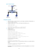
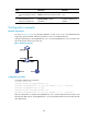
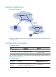
Figure 47 Network diagram
Configuration procedure
1. Add all the interfaces on Switch B to VLAN 10, and configure the IP address of VLAN-interface 10
on Switch A. (Details not shown.)
2. Configure the DHCP server on Switch A and configure DHCP address pool 0.
<SwitchA> system-view
[SwitchA] dhcp enable
[SwitchA] dhcp server ip-pool 0
[SwitchA-dhcp-pool-0] network 10.1.1.0 mask 255.255.255.0
3. Configure Host A (DHCP client) and Host B. (Details not shown.)
4. Configure Switch B:
# Enable DHCP snooping.
<SwitchB> system-view
[SwitchB] dhcp snooping enable
[SwitchB] interface ten-gigabitethernet 1/0/3
[SwitchB-Ten-GigabitEthernet1/0/3] dhcp snooping trust
[SwitchB-Ten-GigabitEthernet1/0/3] quit
[SwitchB] interface ten-gigabitethernet 1/0/1
[SwitchB-Ten-GigabitEthernet1/0/1] dhcp snooping binding record
[SwitchB-Ten-GigabitEthernet1/0/1] quit
# Enable ARP detection for VLAN 10.
[SwitchB] vlan 10
[SwitchB-vlan10] arp detection enable
# Configure the upstream interface as a trusted interface (an interface is an untrusted interface by
default).
[SwitchB-vlan10] interface ten-gigabitethernet 1/0/3
[SwitchB-Ten-GigabitEthernet1/0/3] arp detection trust
[SwitchB-Ten-GigabitEthernet1/0/3] quit
# Configure a static IP source guard binding entry on interface Ten-GigabitEthernet 1/0/2 for user
validity check.
Switch A
Switch B
Host A Host B
XGE1/0/3
Vlan-int10
10.1.1.1/24
Gateway
DHCP server
XGE1/0/1
XGE1/0/3
XGE1/0/2
DHCP client
VLAN 10
DHCP snooping
10.1.1.6
0001-0203-0607