
R21xx-HP FlexFabric 11900 Security Configuration Guide

138
Ste
p
Command
Remarks
2. Enter Layer-2 Ethernet interface
or Layer-2 aggregate interface
view.
interface interface-type interface-number
N/A
3. Enable ARP filtering and
configure a permitted entry.
arp filter binding ip-address
mac-address
By default, ARP filtering is
disabled.
Configuration example
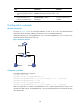
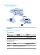
Network requirements
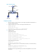
As shown in Figure 49, the IP and MAC addresses of Host A are 10.1.1.2 and 000f-e349-1233
respectively. The IP and MAC addresses of Host B are 10.1.1.3 and 000f-e349-1234.
Configure ARP filtering on Ten-GigabitEthernet 1/0/1 and Ten-GigabitEthernet 1/0/2 of Switch B to
permit ARP packets from the two hosts only.
Figure 49 Network diagram
Configuration procedure
# Configure ARP filtering on Switch B.
<SwitchB> system-view
[SwitchB] interface ten-gigabitethernet 1/0/1
[SwitchB-Ten-GigabitEthernet1/0/1] arp filter binding 10.1.1.2 000f-e349-1233
[SwitchB-Ten-GigabitEthernet1/0/1] quit
[SwitchB] interface ten-gigabitethernet 1/0/2
[SwitchB-Ten-GigabitEthernet1/0/2] arp filter binding 10.1.1.3 000f-e349-1234
After the configuration is complete, Ten-GigabitEthernet 1/0/1 permits ARP packets from Host A, and
discards other ARP packets. Ten-GigabitEthernet 1/0/2 permits ARP packets from Host B and discards
other ARP packets.