HP FlexFabric 11900 Switch Series High Availability Command Reference Part number: 5998-4082 Software version: Release 2105 and later Document version: 6W100-20130515
Legal and notice information © Copyright 2013 Hewlett-Packard Development Company, L.P. No part of this documentation may be reproduced or transmitted in any form or by any means without prior written consent of Hewlett-Packard Development Company, L.P. The information contained herein is subject to change without notice.
Contents Ethernet OAM commands ··········································································································································· 1 display oam ······························································································································································ 1 display oam configuration······································································································································· 5 dis
display cfd service-instance ·································································································································· 48 display cfd status ··················································································································································· 49 DLDP commands ························································································································································· 50 display
display bfd session ················································································································································ 94 reset bfd session statistics ····································································································································· 96 Track commands ························································································································································ 98 displa
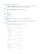
Ethernet OAM commands display oam Use display oam to display the information about an Ethernet OAM connection, including connection status, information contained in Ethernet OAM packet header, and Ethernet OAM packet statistics. Syntax display oam { local | remote } [ interface interface-type interface-number ] Views Any view Predefined user roles network-admin network-operator Parameters local: Displays the Ethernet OAM connection information of the local end.
Par action : FWD Flags Link fault : Not occurred Dying gasp : Not occurred Critical event : Not occurred Local evaluating : COMPLETE Remote evaluating : COMPLETE Packets statistic Packet type Sent Received ----------------------------------------------------------------OAMPDU 100 OAMInformation 80 64 OAMEventNotification 60 36 20 OAMUniqueEventNotification 36 10 OAMDuplicateEventNotification 0 10 Table 1 Command output Field Description Ten-GigabitEthernet1/0/1 Information on
Field Description Critical event Indicates whether a critical error is present. Indicates whether the local-to-remote configuration negotiation is complete: • COMPLETE—The negotiation is completed. • NOTCOMPLETE—The negotiation is uncompleted. Local evaluating Indicates whether the remote-to-local configuration negotiation is complete: • • • • Remote evaluating COMPLETE—The negotiation is completed. NOTCOMPLETE—The negotiation is uncompleted.
Table 2 Command output Field Description Ten-GigabitEthernet1/0/1 Information on Ten-GigabitEthernet 1/0/1. Local Ethernet OAM mode: OAM mode • Active—The port operates in the active Ethernet OAM mode. • Passive—The port operates in the passive Ethernet OAM mode. MAC address MAC address of the remote end. MTU size MTU size, in bytes. Mux action • FWD—The port can send any packets. • DISCARD—The port only sends Ethernet OAMPDUs.
display oam configuration Use display oam configuration to display global Ethernet OAM configuration on the specified port, including the periods and thresholds for Ethernet OAM link error event detection. Syntax display oam configuration [ interface interface-type interface-number ] Views Any view Predefined user roles network-admin network-operator Parameters interface interface-type interface-number: Specifies a port by its type and number.
Threshold : 1 error symbols Errored frame Window : 10 x 100 milliseconds Threshold : 1 error frames Errored frame period Window : 1000 x 10000 frames Threshold : 1 error frames Errored frame seconds Window : 600 x 100 milliseconds Threshold : 1 error seconds Table 3 Command output Field Description Global Global information. Ten-GigabitEthernet1/0/1 Information on Ten-GigabitEthernet 1/0/1. OAM timers Ethernet OAM connection detection timers.
Usage guidelines If you do not specify the interface keyword, this command displays the statistics for the critical Ethernet OAM link events that occurred on all the ports of the switch. Examples # Display the statistics on critical Ethernet OAM link events occurred on all the ports.
Examples # Display the statistics on Ethernet OAM link error events occurred on all the local ports.
Errored frame period : 1 error frames Error running total : 5 error frames Event running total : 5 events OAM remote errored frame seconds summary event Event time stamp : 50022 x 100 milliseconds Errored frame seconds window : 600 x 100 milliseconds Errored frame seconds threshold : 1 error seconds Errored frame seconds : 1 error seconds Error running total : 1 error seconds Event running total : 1 events Table 5 Command output Field Description Ten-GigabitEthernet1 /0/1 Information on T
Field Description Information about local/remote end errored frame seconds events: OAM local/remote errored frame seconds summary event • Event time stamp—Time when an errored frame seconds event occurred. • Errored frame second window—Error frame second detection interval. • Errored Frame seconds threshold—Error threshold that triggers an errored frame seconds event. • Errored frame seconds—Number of detected error frame seconds in the most recent errored frame seconds event.
Default The port uses the global setting. Views Layer 2 Ethernet port view, Layer 3 Ethernet port view Predefined user roles network-admin Parameters threshold-value: Specifies the errored frame event triggering threshold in number of errored frame seconds, in the range of 0 to 4294967295. Usage guidelines The configuration in port view takes effect on the specified port. For a port, the configuration in port view takes precedence. Examples # Set the errored frame event triggering threshold to 100.
Usage guidelines The configuration in port view takes effect on the specified port. For a port, the configuration in port view takes precedence. Examples # Set the errored frame event detection window on Ten-GigabitEthernet 1/0/1 to 2000 milliseconds.
• display oam link-event • oam global errored-frame-period threshold oam errored-frame-period window Use oam errored-frame-period window to set the errored frame period event detection window. Use undo oam errored-frame-period window to restore the default. Syntax oam errored-frame-period window window-value undo oam errored-frame-period window Default The port uses the global setting.
Default The port uses the global setting. Views Layer 2 Ethernet port view, Layer 3 Ethernet port view Predefined user roles network-admin Parameters threshold-value: Specifies the errored frame seconds event triggering threshold in the range of 0 to 900. Usage guidelines The value of the errored frame seconds event triggering threshold cannot be greater than the value of the errored frame seconds event detection window (in seconds). Otherwise, errored frame seconds events cannot be generated.
Parameters window-value: Specifies the errored frame seconds event detection window in the range of 100 to 9000 and in steps of 10 (in 100 milliseconds). Usage guidelines The value of the errored frame seconds event triggering threshold cannot be greater than the value of the errored frame seconds event detection window (in seconds). Otherwise, errored frame seconds events cannot be generated. The configuration in port view takes effect on the specified port.
Examples # Set the errored symbol event triggering threshold to 100. system-view [Sysname] interface ten-gigabitethernet 1/0/1 [Sysname-Ten-GigabitEthernet1/0/1] oam errored-symbol-period threshold 100 Related commands • display oam configuration • display oam link-event • oam global errored-symbol-period threshold oam errored-symbol-period window Use oam errored-symbol-period window to set the errored symbol event detection window.
oam global errored-frame threshold Use oam global errored-frame threshold to set the global errored frame event triggering threshold. Use undo oam global errored-frame threshold to restore the default. Syntax oam global errored-frame threshold threshold-value undo oam global errored-frame threshold Default The errored frame event triggering threshold is 1.
Predefined user roles network-admin Parameters window-value: Specifies the errored frame event detection window in the range of 10 to 600 and in steps of 10 (in 100 milliseconds). Usage guidelines The configuration in system view takes effect on all ports, but has a lower precedence than the configuration in port view. Examples # Set the errored frame event detection window to 2000 milliseconds.
[Sysname] oam global errored-frame-period threshold 100 Related commands • display oam configuration • display oam link-event • oam errored-frame-period threshold oam global errored-frame-period window Use oam global errored-frame-period window to set the global errored frame period event detection window. Use undo oam global errored-frame-period window to restore the default.
Syntax oam global errored-frame-seconds threshold threshold-value undo oam global errored-frame-seconds threshold Default The global errored frame seconds event detection interval is 1. Views System view Predefined user roles network-admin Parameters threshold-value: Specifies the errored frame seconds event triggering threshold in the range of 0 to 900.
Predefined user roles network-admin Parameters window-value: Specifies the errored frame seconds event detection window in the range of 100 to 9000 and in steps of 10 (in 100 milliseconds). Usage guidelines The value of the errored frame seconds event triggering threshold cannot be greater than the value of the errored frame seconds event detection window (in seconds). Otherwise, errored frame seconds events cannot be generated.
Usage guidelines The configuration in system view takes effect on all ports, but has a lower precedence than the configuration in port view. Examples # Set the errored symbol event triggering threshold to 100.
oam global timer hello Use oam global timer hello to configure the global Ethernet OAM handshake packet transmission interval. Use undo oam global timer hello to restore the default. Syntax oam global timer hello interval undo oam global timer hello Default The global Ethernet OAM handshake packet transmission interval is 1000 milliseconds.
Default The global Ethernet OAM connection timeout timer is 5000 milliseconds. Views System view Predefined user roles network-admin Parameters interval: Specifies the Ethernet OAM connection timeout timer, in steps of 100 (in milliseconds). The value range for this argument is 1000 to 25000. Usage guidelines After the timeout timer of an Ethernet OAM connection expires, the local OAM entity ages out its connection with the peer OAM entity, causing the OAM connection to disconnect.
Usage guidelines To change the Ethernet OAM mode of an Ethernet OAM-enabled Ethernet port, first disable Ethernet OAM on the port. Examples # Disable Ethernet OAM on Ten-GigabitEthernet 1/0/1, and then configure Ten-GigabitEthernet 1/0/1 to operate in passive Ethernet OAM mode.
oam timer hello Use oam timer hello to configure the Ethernet OAM handshake packet transmission interval. Use undo oam timer hello to restore the default. Syntax oam timer hello interval undo oam timer hello Default The port uses the global setting. Views Layer 2 Ethernet port view, Layer 3 Ethernet port view Predefined user roles network-admin Parameters interval: Specifies the Ethernet OAM handshake packet transmission interval, in steps of 100 (in milliseconds).
Default The port uses the global setting. Views Layer 2 Ethernet port view, Layer 3 Ethernet port view Predefined user roles network-admin Parameters interval: Specifies the Ethernet OAM connection timeout timer, in steps of 100 (in milliseconds). The value range for this argument is 1000 to 25000. Usage guidelines After the timeout timer of an Ethernet OAM connection expires, the local OAM entity ages out its connection with the peer OAM entity, causing the OAM connection to disconnect.
Examples # Clear the statistics on Ethernet OAM packets and Ethernet OAM link error events of all the ports.
CFD commands cfd cc enable Use cfd cc enable to enable CCM sending on a specified MEP. Use undo cfd cc enable to disable CCM sending on a specified MEP. Syntax cfd cc service-instance instance-id mep mep-id enable undo cfd cc service-instance instance-id mep mep-id enable Default The CCM sending function is disabled.
Default The value of this field is 4 for all CCMs sent. Views System view Predefined user roles network-admin Parameters interval interval-value: Specifies the value of the interval field in CCM messages. The value range for the interval field is 1 to 7. This Switch Series does not support an interval field value in the range of 1 to 3. If you configure the interval field value as 1, 2, or 3, the value 4 takes effect.
Views System view Predefined user roles network-admin Examples # Enable CFD. system-view [Sysname] cfd enable cfd linktrace Use cfd linktrace to find the path between the source MEP and target MP, which is achieved through the transmission of LTMs between the two and detection of the responding LTRs.
Field Description Last MAC MAC address of the last-hop device the LTM passes. Indicates whether the forwarding device found the destination MAC address in its MAC address table. When the standard version (IEEE 802.1ag) of CFD is used: Relay Action • Hit—The current device is the destination device. • FDB—The forwarding device found the destination MAC address. • MPDB—The destination MAC address is not found, or the destination MAC address is found in the MEP or MIP database.
Related commands • cfd linktrace • display cfd linktrace-reply auto-detection cfd loopback Use cfd loopback to enable LB function so that LBMs can be sent from the source MEP to the target MP, and LBR messages can be received. Syntax cfd loopback service-instance instance-id mep mep-id { target-mac mac-address | target-mep target-mep-id } [ number number ] Default LB is not enabled.
Table 8 Command output Field Description Loopback to 0010-FC00-6512 with the sequence number start from 1101-43404 Sends LBMs to 0010-FC00-6512 with the sequence number starting with 1101-43404. Reply from 0010-FC00-6512 Reply from the MP with the MAC address 0010-FC00-6512. sequence number Sequence number in the LBR messages. time=5ms The interval between the sending of LBMs and receiving of LBRs is 5 milliseconds. Send Number of LBMs sent. Received Number of LBR messages received.
mac mac-address subnumber: Specifies an MD name comprising the MAC address and an integer, where mac-address represents the MAC address of the MD, and subnumber is in the range of 0 to 65535. none: Specifies that no MD name is carried in the packets sent by the MEP. Usage guidelines An MD name must be in compliant with the specifications in table 21-19 in IEEE802.1ag-2007. You can create only one MD with a specific level.
outbound: Creates an outward-facing MEP. Usage guidelines In creating a MEP, the service instance you specified defines the MD and MA to which the MEP belongs. You cannot create a MEP if the MEP ID is not included in the MEP list of the relevant service instance.
Examples # Create a MEP list that includes MEP 9 through MEP 15 in service instance 5. system-view [Sysname] cfd md test_md level 3 [Sysname] cfd service-instance 5 ma-id vlan-based md test_md vlan 100 [Sysname] cfd meplist 9 to 15 service-instance 5 Related commands • cfd md • cfd service-instance cfd mip-rule Use cfd mip-rule to configure the rules for generating MIPs. The system automatically generates MIPs on each port according to the rules configured.
Syntax cfd service-instance instance-id ma-id { icc-based icc-name | integer ma-num | string ma-name | vlan-based [ vlan-id ] } [ ma-index index-value ] md md-name vlan vlan-id undo cfd service-instance instance-id Default No service instance exists. Views System view Predefined user roles network-admin Parameters service-instance instance-id: Specifies a service instance ID in the range of 1 to 32767. ma-id: Creates an MA. icc-based icc-name: Specifies that an MA is identified by an ICC.
When you delete a service instance, you are deleting the configurations related to that service instance as well. Deleting a service instance not only breaks up the connection between the service instance and the relevant MA, but also deletes the MA itself. Examples # Create a level-3 MD named test_md and create service instance 5, in which the MA is identified by a VLAN and serves VLAN 100.
Table 9 Command output Field Description Service instance Service instance to which the MEPs that send LTMs belong. MEP ID ID of the MEP that sends LTMs. MAC Address Source MAC address in the LTR message. TTL Hop count when LTM passes the device. Last MAC MAC address of the last-hop device the LTM passes. Indicates whether the forwarding device found the destination MAC address in its MAC address table. When the standard version (IEEE 802.
000F-E269-A852 62 0000-FC00-6505 FDB 0000-FC00-6508 61 000F-E269-A852 Hit Service instance: 2 MEP ID: 1023 Target MEP ID: 2025 TTL: 64 MAC Address TTL Last MAC Relay Action 0000-FC00-6508 61 000F-E269-A852 Hit Time: 2012/05/22 10:44:06 Table 10 Command output Field Description Service instance Service instance to which the MEPs that sent LTM messages belong. MEP ID ID of the MEP that sends LTMs. Time Time of the LTMs automatically sent. Target MEP ID ID of the target MEP.
Maintenance domains configured: 7 in total Level Index Maintenance domain MD format MD ID 0 1 md_0 CHARSTRING md_0 1 2 md_1 DNS dns1 2 3 md_2 MAC 0001-00 md_3 NONE Without 01-0001-1 3 4 ID Table 11 Command output Field Description Maintenance domains configured Number of MDs configured. Level Level of MD. Index MD index. Maintenance domain Name of MD. MD name format: • CHARSTRING—Character string. MD format • DNS—DNS name. • MAC—MAC address and an integer.
Usage guidelines The neighbor of an inward-facing MEP is the neighbor of the service instance corresponding to the MEP. Examples # Display the attribute and operating information of MEP 50 in service instance 1.
Field Description Maintenance domain MD to which a MEP belongs. (If the MD does not have a name, this field is displayed as Without ID.) Maintenance domain index Index of the MD where the MEP resides. Maintenance association MA to which a MEP belongs. Maintenance association index Index of the MA where the MEP resides. Level Level of the MD. VLAN VLAN to which the MA belongs. Direction Direction of the MEPs. Current state State of MEP, either Active or Inactive.
Field Description One or more streams of error CCMs is received. The last-received CCM: Display the content of the last error CCM when one or more error CCMs are received. (This information is displayed only when error CCMs are received.) Maintenance domain Maintenance association MEP Sequence Number MD of the last error CCM message. If this field is not supported, a hyphen (-) is displayed. MA of the last error CCM message. If this field is not supported, a hyphen (-) is displayed.
Syntax display cfd mp [ interface interface-type interface-number ] Views Any view Predefined user roles network-admin network-operator Parameters interface interface-type interface-number: Displays the MP information on a port specified by its port type and port number. If this option is not specified, MP information on all ports is displayed. Usage guidelines The output is arranged by port name. On a port, the output shows MPs that serve VLANs, and then shows MPs that serve no VLANs.
Field Description Service instance Service instance to which the MP belongs. Maintenance domain MD to which an MP belongs. Maintenance domain index Index of the MD to which an MP belongs. Maintenance association MA to which an MP belongs. Maintenance association index Index of the MA to which an MP belongs. Direction Direction of the MEP, inbound or outbound. display cfd remote-mep Use display cfd remote-mep to display information about a remote MEP.
Field Description State of the interface indicated by the last CCM received from the remote MEP: • • • • • MAC Status UP—The interface is ready to pass packets. DOWN—The interface cannot pass packets. TESTING—The interface is in some test mode. UNKNOWN—The interface status cannot be determined. DORMANT—The interface is not in a state to pass packets. Instead, it is in a pending state, waiting for some external event. • NOT-PRESENT—Some component of the interface is missing.
Level: 6 VLAN: 6 MEP ID: 731 MIP rule: NONE CCM interval: 1s Direction: Outbound Interface: Ten-GigabitEthernet1/0/2 Table 15 Command output Field Description Service instances are configured. Number of service instances configured. Service instance Service instance ID. Maintenance domain MD of the service instances. (If the MD does not have a name, this field displays Without ID.) Maintenance domain index Index of the MD to which the service instances belong.
DLDP commands display dldp Use display dldp to display DLDP configuration. Syntax display dldp [ interface interface-type interface-number ] Views Any view Predefined user roles network-admin network-operator Parameters interface interface-type interface-number: Specifies an interface by its type and number. Usage guidelines If no port is specified, this command displays global and port-specific DLDP configuration. If a port is specified, this command displays only the DLDP configuration on the port.
Interface Ethernet1/1 DLDP port state: Bidirectional Number of the port’s neighbors: 1 Neighbor MAC address: 0023-8956-3600 Neighbor port index: 79 Neighbor state: Confirmed Neighbor aged time: 13s Table 16 Command output Field Description DLDP global status Global DLDP state (Enabled or Disabled). DLDP advertisement interval Interval for sending Advertisement packets (in seconds) to maintain neighbor relations. DLDP authentication-mode DLDP authentication mode (None, Simple, or md5).
Views Any view Predefined user roles network-admin network-operator Parameters interface interface-type interface-number: Specifies a port by its type and number. Usage guidelines If no port is specified, this command displays the statistics on the DLDP packets passing through all the DLDP-enabled ports. Examples # Display the statistics on the DLDP packets passing through all the DLDP-enabled ports.
dldp authentication-mode Use dldp authentication-mode to configure DLDP authentication. Use undo dldp authentication-mode to restore the default. Syntax dldp authentication-mode { md5 | none | simple } undo dldp authentication-mode Default DLDP authentication is not performed. Views System view Predefined user roles network-admin Parameters md5: Specifies the MD5 authentication mode. none: Specifies not to perform authentication. simple: Specifies the plain text authentication mode.
Use undo dldp authentication-password to restore the default. Syntax dldp authentication-password { cipher cipher | simple simple } undo dldp authentication-password Default No DLDP authentication password is configured. Views System view Predefined user roles network-admin Parameters cipher cipher: Sets a ciphertext password. The cipher argument is a case-sensitive string of 1 to 53 characters. simple simple: Sets a plaintext password.
Syntax dldp delaydown-timer time undo dldp delaydown-timer Default The setting of the DelayDown timer is 1 second. Views System view Predefined user roles network-admin Parameters time: Specifies the DelayDown timer in the range of 1 to 5 seconds. Usage guidelines The DelayDown timer configured by using this command applies to all DLDP-enabled ports. Examples # Set the DelayDown timer to 2 seconds.
[Sysname] interface ethernet 1/1 [Sysname-Ethernet1/1] dldp enable Related commands • display dldp • dldp global enable dldp global enable Use dldp global enable to enable DLDP globally. Use undo dldp global enable to disable DLDP globally. Syntax dldp global enable undo dldp global enable Default DLDP is disabled globally. Views System view Predefined user roles network-admin Usage guidelines DLDP can take effect only after you enable it globally and on a port. Examples # Enable DLDP globally.
Predefined user roles network-admin Parameters time: Specifies the interval for sending Advertisement packets, in the range of 1 to 100 seconds. Usage guidelines This command applies to all DLDP-enabled ports. To enable DLDP to operate correctly, make sure the intervals for sending Advertisement packets configured on the two ends of a link are the same. Examples # Set the interval for sending Advertisement packets to 20 seconds.
reset dldp statistics Use reset dldp statistics to clear the statistics on DLDP packets passing through a port. Syntax reset dldp statistics [ interface interface-type interface-number ] Views User view Predefined user roles network-admin Parameters interface interface-type interface-number: Clears the statistics on DLDP packets passing through a port. interface-type interface-number represents a port by its type and number.
VRRP commands The term interface in the VRRP feature refers to Layer 3 interfaces, including VLAN interfaces and Layer 3 Ethernet interfaces. You can set an Ethernet port as a Layer 3 interface by using the port link-mode route command (see Layer 2—LAN Switching Configuration Guide). IPv4 VRRP commands display vrrp Use display vrrp to display the states of IPv4 VRRP groups.
Table 18 Command output (in standard mode) Field Description Running Mode VRRP operating mode (standard mode). Total number of virtual routers Total number of VRRP groups. Interface Interface where the VRRP group is configured. VRID Virtual router ID (VRRP group number). Status of the router in the VRRP group: • Master. • Backup. State • Initialize. • Inactive. Current priority of the router.
Field Description Total number of virtual routers Total number of VRRP groups. Interface Interface where the VRRP group is configured. VRID Virtual router ID (VRRP group number). Adver Timer VRRP advertisement sending interval in centiseconds. Admin Status Administrative status: up or down. Status of the router in the VRRP group: • Master. State • Backup. • Initialize. • Inactive. Config Pri Configured priority of the router, which is configured through the vrrp vrid priority command.
Field Description Switchover Switchover mode. When the status of the associated track entry becomes negative, the backup immediately becomes the master. display vrrp statistics Use display vrrp statistics to display statistics for IPv4 VRRP groups.
Table 20 Command output (in standard mode) Field Description Interface Interface where the VRRP group is configured. VRID VRRP group number. CheckSum Errors Number of packets with checksum errors. Version Errors Number of packets with version errors. Invalid Pkts Rcvd Number of received packets of invalid packet types. Unexpected Pkts Rcvd Number of received unexpected packets. Advertisement Interval Errors Number of packets with advertisement interval errors.
Predefined user roles network-admin Parameters interface interface-type interface-number: Specifies an interface by its type and number. vrid virtual-router-id: Specifies an IPv4 VRRP group by its virtual router ID in the range of 1 to 255. Usage guidelines If no interface or VRRP group is specified, this command clears statistics for all IPv4 VRRP groups. If only an interface is specified, this command clears statistics for all IPv4 VRRP groups on the specified interface.
system-view [Sysname] interface vlan-interface 2 [Sysname-Vlan-interface2] undo vrrp check-ttl enable vrrp version Use vrrp version to specify the version of IPv4 VRRP on an interface. Use undo vrrp version to restore the default. Syntax vrrp version version-number undo vrrp version Default VRRPv3 is used. Views Interface view Predefined user roles network-admin Parameters version-number: Specifies a VRRP version.
Predefined user roles network-admin Parameters virtual-router-id: Specifies an IPv4 VRRP group by its virtual router ID in the range of 1 to 255. md5: Specifies the MD5 authentication mode. simple: Specifies the simple authentication mode. cipher: Sets a ciphertext authentication key. plain: Sets a plaintext authentication key. key: Sets the authentication key. This argument is case sensitive.
vrrp vrid preempt-mode Use vrrp vrid preempt-mode to enable the preemptive mode for the device in an IPv4 VRRP group and configure the preemption delay. Use undo vrrp vrid preempt-mode to disable the preemptive mode for the device in an IPv4 VRRP group. Use undo vrrp vrid preempt-mode delay to restore the default preemption delay.
Use undo vrrp vrid priority to restore the default. Syntax vrrp vrid virtual-router-id priority priority-value undo vrrp vrid virtual-router-id priority Default The priority of a device in an IPv4 VRRP group is 100. Views Interface view Predefined user roles network-admin Parameters virtual-router-id: Specifies an IPv4 VRRP group by its virtual router ID in the range of 1 to 255. priority-value: Specifies a priority value in the range of 1 to 254. A higher number indicates a higher priority.
Views Interface view Predefined user roles network-admin Parameters virtual-router-id: Specifies an IPv4 VRRP group by its virtual router ID in the range of 1 to 255. Usage guidelines You can use this command to temporarily disable an IPv4 VRRP group. After this command is configured, the VRRP group stays in initialized state, and its configurations remain unchanged. You can change its configuration and your changes take effect when you enable the VRRP group again. Examples # Disable IPv4 VRRP group 1.
In VRRPv2, all routers in an IPv4 VRRP group must have the same interval for sending VRRP advertisements. In VRRPv3, the routers in an IPv4 VRRP group can have different intervals for sending VRRP advertisements. The master in the VRRP group sends VRRP advertisements at the specified interval and carries the interval attribute in the advertisements. After a backup receives the advertisement, it records the interval in the advertisement.
reduced priority-reduced: Reduces the priority of the router in the VRRP group by a specific value when the state of the specified track entry changes to negative. The value range for the priority-reduced argument is 1 to 255. switchover: Enables the router in backup state to take over as the master immediately after the specified track entry changes to the negative state.
Predefined user roles network-admin Parameters virtual-router-id: Specifies an IPv4 VRRP group by its virtual router ID in the range of 1 to 255. virtual-address: Specifies a virtual IP address, which cannot be an all-zero address (0.0.0.0); a broadcast address (255.255.255.255); a loopback address; an IP address of other than Class A, Class B, and Class C; or an invalid IP address (for example, 0.0.0.1). Usage guidelines You can assign up to 16 virtual IP addresses to an IPv4 VRRP group.
verbose: Displays detailed IPv6 VRRP group information. If the verbose keyword is not specified, this command displays brief IPv6 VRRP group information. Usage guidelines If no interface or VRRP group is specified, this command displays the states of all IPv6 VRRP groups. If only an interface is specified, this command displays the states of all IPv6 VRRP groups on the specified interface.
Total number of virtual routers : 1 Interface Vlan-interface2 VRID : 1 Adver Timer : 100 Admin Status : Up State : Master Config Pri : 150 Running Pri : 150 Preempt Mode : Yes Delay Time : 10 Auth Type : None Virtual IP : FE80::1 Virtual MAC : 0000-5e00-0201 Master IP : FE80::2 VRRP Track Information: Track Object : 1 State : Positive Pri Reduced : 50 Table 22 Command output (in standard mode) Field Description Running Mode VRRP operating mode (standard mode).
Field Description VRRP Track Information Track entry information. This field is displayed only after you have configured the vrrp ipv6 vrid track command. Track Object Track entry which is associated with the VRRP group. Track entry state: State • Negative. • Positive. • NotReady. Pri Reduced Value by which the priority decreases when the status of the associated track entry becomes negative. Switchover Switchover mode.
Invalid Auth Type : 0 Auth Failures : 0 Packet Length Errors : 0 Auth Type Mismatch : 0 Become Master : 1 Address List Errors : 0 Adver Rcvd : 0 Priority Zero Pkts Rcvd : 0 Adver Sent : 425 Priority Zero Pkts Sent : 0 Global statistics CheckSum Errors : 0 Version Errors : 0 VRID Errors : 0 Table 23 Command output (in standard mode) Field Description Interface Interface where the VRRP group is configured. VRID VRRP group number.
reset vrrp ipv6 statistics Use reset vrrp ipv6 statistics to clear statistics for IPv6 VRRP groups. Syntax reset vrrp ipv6 statistics [ interface interface-type interface-number [ vrid virtual-router-id ] ] Views User view Predefined user roles network-admin Parameters interface interface-type interface-number: Specifies an interface by its type and number. vrid virtual-router-id: Specifies an IPv6 VRRP group by its virtual router ID in the range of 1 to 255.
Parameters virtual-router-id: Specifies an IPv6 VRRP group by its virtual router ID in the range of 1 to 255. delay delay-value: Specifies a preemption delay time in the range of 0 to 255, in seconds. The default setting is 0 seconds. Usage guidelines In non-preemptive mode, when a router in the IPv6 VRRP group becomes the master, it acts as the master as long as it operates correctly, even if a backup is assigned a higher priority later.
Usage guidelines VRRP determines the role (master or backup) of each router in a VRRP group by priority. A router with a higher priority is more likely to become the master. The VRRP priority is in the range of 0 to 255. A greater number represents a higher priority. Priorities 1 to 254 are configurable. Priority 0 is reserved for special uses, and priority 255 is for the IP address owner.
vrrp ipv6 vrid timer advertise Use vrrp ipv6 vrid timer advertise to configure the interval at which the master in an IPv6 VRRP group sends VRRP advertisements. Use undo vrrp ipv6 vrid timer advertise to restore the default. Syntax vrrp ipv6 vrid virtual-router-id timer advertise adver-interval undo vrrp ipv6 vrid virtual-router-id timer advertise Default The master in an IPv6 VRRP group sends VRRP advertisements at an interval of 100 centiseconds.
vrrp ipv6 vrid track Use vrrp ipv6 vrid track to associate an IPv6 VRRP group with a track entry and control master switchover in the VRRP group in response to changes (such as uplink state changes) detected by the track entry. Use undo vrrp ipv6 vrid track to remove the association between an IPv6 VRRP group and a track entry. If no track entry is specified, the association between the VRRP group and any track entry is removed.
Examples # Associate IPv6 VRRP group 1 on VLAN-interface 2 with track entry 1 and decrease the priority of the router in the VRRP group by 50 when the state of track entry 1 changes to negative.
Examples # Create IPv6 VRRP group 1 and assign virtual IPv6 address fe80::10 to the VRRP group. Then assign virtual IPv6 address 1::10 to the VRRP group.
BFD commands The term interface in the BFD feature refers to Layer 3 interfaces, including VLAN interfaces and Layer 3 Ethernet interfaces. You can set an Ethernet port as a Layer 3 interface by using the port link-mode route command (see Layer 2—LAN Switching Configuration Guide). bfd authentication-mode Use bfd authentication-mode to configure the BFD authentication mode for single-hop BFD control packets. Use undo bfd authentication-mode to restore the default.
bfd demand enable Use bfd demand enable to enable the Demand BFD session mode. Use undo bfd demand enable to restore the default. Syntax bfd demand enable undo bfd demand enable Default The BFD session is in Asynchronous mode. Views Interface view Predefined user roles network-admin Usage guidelines In demand mode, no BFD control packets are exchanged after the session is established.
Parameters value: Specifies a single-hop detection time multiplier in the range of 3 to 50. Usage guidelines The detection time multiplier determines the maximum number of concurrent BFD packets (including control packets and echo packets) that can be discarded. Table 24 shows the detection interval calculation methods.
[Sysname] interface vlan-interface 11 [Sysname-Vlan-interface11] bfd echo enable bfd echo-source-ip Use bfd echo-source-ip to configure the source IP address of BFD echo packets. Use undo bfd echo-source-ip to remove the configured source IP address of BFD echo packets. Syntax bfd echo-source-ip ip-address undo bfd echo-source-ip Default No source IP address is configured for BFD echo packets.
Parameters ipv6-address: Specifies the source IPv6 address for BFD echo packets. Usage guidelines The source IPv6 address of echo packets can only be a global unicast address. The source IPv6 address cannot be on the same network segment as any local interface's IP address. Otherwise, a large number of ICMP redirect packets may be sent from the peer, resulting in link congestion. Examples # Configure the source IPv6 address of BFD echo packets as 80::2.
Use undo bfd min-receive-interval to restore the default. Syntax bfd min-receive-interval value undo bfd min-receive-interval Default The minimum interval for receiving single-hop BFD control packets is 1000 milliseconds. Views Interface view Predefined user roles network-admin Parameters value: Specifies the minimum interval for receiving single-hop BFD control packets, in milliseconds. The value range for this argument is 100 to 1000.
Parameters value: Specifies the minimum interval for transmitting single-hop BFD control packets, in milliseconds. The value range for this argument is 100 to 1000. Usage guidelines Use this command to make sure that the BFD packet sending rate does not exceed the device capability.
Examples # Configure the simple authentication mode for multi-hop BFD control packets, setting the authentication key ID to 1 and password to 123456. system-view [Sysname] bfd multi-hop authentication-mode simple 1 plain 123456 bfd multi-hop destination-port Use bfd multi-hop destination-port to configure the destination port number for multi-hop BFD control packets. Use undo bfd multi-hop destination-port to restore the default.
Parameters value: Specifies the multi-hop detection time multiplier in the range of 3 to 50. Usage guidelines The detection time multiplier determines the maximum number of concurrent BFD control packets that can be discarded. Table 25 shows the detection interval calculation methods.
Examples # Configure the minimum interval for receiving multi-hop BFD control packets as 500 milliseconds. system-view [Sysname] bfd multi-hop min-receive-interval 500 bfd multi-hop min-transmit-interval Use bfd multi-hop min-transmit-interval to configure the minimum interval for transmitting multi-hop BFD control packets. Use undo bfd multi-hop min-transmit-interval to restore the default.
Views System view Predefined user roles network-admin Parameters active: Uses the active mode. In active mode, BFD actively transmits BFD control packets to the remote device, regardless of whether it receives a BFD control packet from the remote device. passive: Uses the passive mode. In passive mode, BFD does not actively transmit a BFD control packet to the remote end; it transmits a BFD control packet only after receiving a BFD control packet from the remote end.
513/513 1.1.1.1 1.1.1.2 Up 2297ms Vlan11 # Display all IPv6 BFD session information. display bfd session Total Session Num: 1 Up Session Num: 1 Init Mode: Active IPv6 Session Working Under Ctrl Mode: Local Discr: 513 Remote Discr: 513 Source IP: FE80::20C:29FF:FED4:7171 Destination IP: FE80::20C:29FF:FE72:AC4D Session State: Up Interface: Vlan11 # Display detailed IPv4 BFD session information.
Protocol: OSPF6 Diag Info: No Diagnostic Table 26 Command output Field Description Total Session Num Total number of BFD sessions. Up Session Num Total number of active BFD sessions. Init Mode BFD operating mode, active or passive. IPv4/IPv6 BFD session mode: Session Working Under Ctrl Mode • Ctrl—Control packet mode. • Echo—Echo packet mode. Local Discr/LD Local ID of the session. Remote Discr/RD Remote ID of the session. Source IP/SourceAddr Source IP address of the session.
Views User view Predefined user roles network-admin Examples # Clear the BFD session statistics.
Track commands display track Use display track to display track entry information. Syntax display track { track-entry-number | all } Views Any view Predefined user roles network-admin network-operator Parameters track-entry-number: Displays information about the specified track entry. The value range for the track-entry-number argument is 1 to 1024. all: Displays information about all track entries. Examples # Display information about all track entries.
Interface: Vlan-interface3 Protocol: IPv4 Table 27 Command output Field Description Track ID ID of a track entry. States of a track entry: State • Positive—The tracked object functions properly. • NotReady—The tracked object is invalid. • Negative—The tracked object is abnormal. notify 13 seconds later The Track module notifies the application modules of the track entry state change 13 seconds later. The information is not displayed after the Track module notifies the application modules.
track bfd echo Use track bfd echo to create a track entry and associate it with a BFD session. Use undo track to remove the track entry. Syntax track track-entry-number bfd echo interface interface-type interface-number remote ip remote-ip local ip local-ip [ delay { negative negative-time | positive positive-time } * ] undo track track-entry-number Default No track entry exists.
Related commands display track track nqa Use track nqa to create a track entry and associate it with the specified reaction entry of the NQA test group. Use undo track to remove the track entry. Syntax track track-entry-number nqa entry admin-name operation-tag reaction item-number [ delay { negative negative-time | positive positive-time } * ] undo track track-entry-number Default No track entry exists.
Related commands display track track interface Use track interface to create a track entry and associate it with the physical state of a specific interface. Use undo track to remove the track entry. Syntax track track-entry-number interface interface-type interface-number [ delay { negative negative-time | positive positive-time } * ] undo track track-entry-number Default No track entry exists.
Related commands • display track • display ip interface brief (Layer 3—IP Services Command Reference) track interface protocol Use track interface protocol to create a track entry and associate it with the protocol state of a specific interface. Use undo track to remove the track entry.
Examples # Create track entry 1 and associate it with the IPv4 protocol state of VLAN-interface 2.
Support and other resources Contacting HP For worldwide technical support information, see the HP support website: http://www.hp.
Conventions This section describes the conventions used in this documentation set. Command conventions Convention Description Boldface Bold text represents commands and keywords that you enter literally as shown. Italic Italic text represents arguments that you replace with actual values. [] Square brackets enclose syntax choices (keywords or arguments) that are optional. { x | y | ... } Braces enclose a set of required syntax choices separated by vertical bars, from which you select one.
Network topology icons Represents a generic network device, such as a router, switch, or firewall. Represents a routing-capable device, such as a router or Layer 3 switch. Represents a generic switch, such as a Layer 2 or Layer 3 switch, or a router that supports Layer 2 forwarding and other Layer 2 features. Represents an access controller, a unified wired-WLAN module, or the switching engine on a unified wired-WLAN switch. Represents an access point.
Index BCDORSTVW display cfd service-instance,48 B display cfd status,49 bfd authentication-mode,84 display dldp,50 bfd demand enable,85 display dldp statistics,51 bfd detect-multiplier,85 display oam,1 bfd echo enable,86 display oam configuration,5 bfd echo-source-ip,87 display oam critical-event,6 bfd echo-source-ipv6,87 display oam link-event,7 bfd min-echo-receive-interval,88 display track,98 bfd min-receive-interval,88 display vrrp,59 bfd min-transmit-interval,89 display vrrp ipv6,72
oam global errored-symbol-period window,22 track nqa,101 oam global timer hello,23 V oam global timer keepalive,23 vrrp check-ttl enable,64 oam mode,24 vrrp ipv6 vrid preempt-mode,77 oam remote-failure action,25 vrrp ipv6 vrid priority,78 oam timer hello,26 vrrp ipv6 vrid shutdown,79 oam timer keepalive,26 vrrp ipv6 vrid timer advertise,80 R vrrp ipv6 vrid track,81 reset bfd session statistics,96 vrrp ipv6 vrid virtual-ip,82 reset dldp statistics,58 vrrp version,65 reset oam,27 vrrp vri