HP 11900/10500/7500 20G Unified Wired-WLAN Module Basic Configuration Guide Part number: 5998-3914 Software version: 2507P22 (HP 11900/10500/7500 20G Module) Document version: 6W101-20140418
Legal and notice information © Copyright 2014 Hewlett-Packard Development Company, L.P. No part of this documentation may be reproduced or transmitted in any form or by any means without prior written consent of Hewlett-Packard Development Company, L.P. The information contained herein is subject to change without notice.
Contents Configuring basic settings for the HP 11900/10500/7500 20G unified wired-WLAN module ························ 1 Configuring basic settings ················································································································································ 1 Configuring the internal interfaces of the switch ···································································································1 Configuring the 11900/10500/7500 20G unified wired-WLAN module ···
Configuring basic settings for the HP 11900/10500/7500 20G unified wired-WLAN module Support for this feature may vary depending on your device model. For more information, see About the Configuration Guides for HP Unified Wired-WLAN Products. The HP 11900/10500/7500 20G unified wired-WLAN module is only applicable to the HP 7502/7503/7503-S/7506/7506-V/7510, HP 10504/10508/10508-V/10512 switches, and HP FlexFabric 11900 switch series.
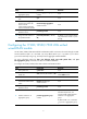
Step Command Remarks 6. Add the interface to an aggregation group. port link-aggregation group number N/A 7. Exit from Ethernet interface view. quit N/A 8. Enter view of the aggregate interface that connects the switch to the HP 11900/10500/7500 20G unified wired-WLAN module. interface bridge-aggregation interface-number N/A Set the link type of the interface to trunk.
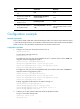
Step Command Remarks 7. Exit from Ethernet interface view. quit N/A 8. Enter view of the aggregate interface that connects the module to the switch. interface bridge-aggregation interface-number N/A Set the link type of the interface to trunk. port link-type trunk N/A port trunk permit vlan { vlan-id-list | all } By default, a trunk interface allows only packets from VLAN 1 to pass through. 9. 10. Assign the trunk interface to the specified VLANs.
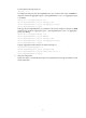
# Create VLAN 8 through VLAN 10. [AC]vlan 8 to 10 # Configure the link type of the Ten-GigabitEthernet1/0/1 interface of the switch as trunk and assign the interface to aggregation group 1 (Ten-GigabitEthernet 1/0/1 is in aggregation group 1 by default).
Support and other resources Contacting HP For worldwide technical support information, see the HP support website: http://www.hp.
Conventions This section describes the conventions used in this documentation set. Command conventions Convention Description Boldface Bold text represents commands and keywords that you enter literally as shown. Italic Italic text represents arguments that you replace with actual values. [] Square brackets enclose syntax choices (keywords or arguments) that are optional. { x | y | ... } Braces enclose a set of required syntax choices separated by vertical bars, from which you select one.
Network topology icons Represents a generic network device, such as a router, switch, or firewall. Represents a routing-capable device, such as a router or Layer 3 switch. Represents a generic switch, such as a Layer 2 or Layer 3 switch, or a router that supports Layer 2 forwarding and other Layer 2 features. Represents an access controller, a unified wired-WLAN module, or the switching engine on a unified wired-WLAN switch. Represents an access point.
Index CR C Conventions,6 Configuration example,3 R Configuring basic settings,1 Related information,5 Contacting HP,5 8