HP FlexFabric 5930 Switch Series Installation Guide 5998-4630 Part number: 5998-4630 Document version: 6W100-20131024
Legal and notice information © Copyright 2013 Hewlett-Packard Development Company, L.P. No part of this documentation may be reproduced or transmitted in any form or by any means without prior written consent of Hewlett-Packard Development Company, L.P. The information contained herein is subject to change without notice.
Contents Preparing for installation ············································································································································· 3 Safety recommendations ·················································································································································· 3 Examining the installation site ································································································································
Accessing the IRF fabric to verify the configuration ··································································································· 33 Maintenance and troubleshooting ···························································································································· 34 Power supply failure ······················································································································································ 34 Fan failure ········
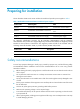
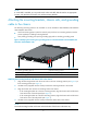
Preparing for installation The HP FlexFabric 5930 Switch Series includes the models and provides power supplies in Table 1.
Examining the installation site The HP FlexFabric 5930 switches must be used indoors. Mount your switch in a rack and make sure: • Adequate clearance is reserved at the air inlet and exhaust vents for ventilation. • The rack has a good ventilation system. • Identify the hot aisle and cold aisle at the installation site, and make sure ambient air flows into the switch from the cold aisle and exhausts to the hot aisle.
Table 3 Harmful gas limits in the equipment room Gas Maximum concentration (mg/m3) SO2 0.2 H2S 0.006 NH3 0.05 Cl2 0.01 EMI All electromagnetic interference (EMI) sources, from outside or inside of the switch and application system, adversely affect the switch in a conduction pattern of capacitance coupling, inductance coupling, electromagnetic wave radiation, or common impedance (including the grounding system) coupling.
Installing the switch CAUTION: Keep the tamper-proof seal on a mounting screw on the chassis cover intact, and if you want to open the chassis, contact HP for permission. Otherwise, HP shall not be liable for any consequence caused thereby.
• To secure the switch to the rack, you must install not only mounting brackets, but also chassis rails and slide rails. Table 4 Distance requirement between the front and rear posts Device model Installation method Minimum distance Maximum distance HP FlexFabric 5930 Using mounting bracket and chassis rails 405 mm (15.94 in) 854 mm (33.
NOTE: If a rack shelf is available, you can put the switch on the rack shelf, slide the switch to an appropriate location, and attach the switch to the rack with the mounting brackets.
Connecting the grounding cable to the chassis CAUTION: The primary grounding point and auxiliary grounding point 1 are located on the left side panel. If you use one of these grounding points, you must connect the grounding cable to the grounding point before you mount the switch in the rack. HP recommends that you use the primary grounding point or auxiliary grounding point 1 because the grounding cable and grounding screw that come with the switch are suitable only for these two grounding points.
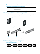
Figure 7 Attaching the front mounting brackets/chassis rails to the chassis Attaching the slide rails to the rack 1. Identify the rack attachment position for the slide rails. 2. Install cage nuts (user-supplied) in the mounting holes in the rack posts. 3. Align the screw holes in one slide rail with the cage nuts in the rack post on one side, and use screws (user-supplied) to attach the slide rail to the rack, as shown in Figure 8. 4.
To mount the switch in the rack: 1. Wear an ESD-preventive wrist strap and make sure it makes good skin contact and is well grounded. 2. Verify that the mounting brackets and chassis rails have been securely attached to the switch chassis. 3. Verify that the slide rails have been correctly attached to the rear rack posts. 4. Install cage nuts (user-supplied) to the front rack posts and make sure they are at the same level as the slide rails. 5.
Figure 10 Mounting the switch in the rack (2) Grounding the switch WARNING! Correctly connecting the switch grounding cable is crucial to lightning protection and EMI protection. The power input end of the switch has a noise filter, whose central ground is directly connected to the chassis to form the chassis ground (commonly known as PGND).
If a grounding strip is available at the installation site, connect the grounding cable to the grounding strip. To connect the grounding cable: 1. Attach the two-hole grounding lug at one end of the grounding cable to a grounding point on the switch chassis (see "Connecting the grounding cable to the chassis"). 2. Remove the hex nut of a grounding post on the grounding strip. 3.
NOTE: If the ground contact in the power outlet is not connected to the ground, report the problem and reconstruct the grounding system. Figure 12 Grounding through the PE wire of the AC power cord (1) Three-wire AC power cable (2) Chassis rear panel NOTE: To guarantee the grounding effect, use the grounding cable provided with the switch to connect to the grounding strip in the equipment room as long as possible.
CAUTION: To prevent damage to the fan tray or the connectors on the backplane, insert the fan tray gently. If you encounter a hard resistance while inserting the fan tray, pull out the fan tray and insert it again. To install a fan tray: 1. Wear an ESD-preventive wrist strap and make sure it makes good skin contact and is well grounded. 2. Unpack the fan tray and check that the fan tray model is correct. 3.
Installing/removing a power supply WARNING! • The switches do not support intermixing of AC and DC power supplies. • In power redundancy mode, you can replace a power supply without powering off the switch but must strictly follow the installation and procedures in Figure 14 and Figure 15 to avoid any bodily injury or damage to the switch. The HP FlexFabric 5930 switches come with both power supply slots empty and the power filler modules as accessories.
The slot is foolproof. If you cannot insert the power supply into the slot, re-orient the power supply rather than use excessive force to push it in. Figure 16 Installing a power supply Figure 17 Installing a power filler module Removing a power supply CAUTION: If the switch has two power supplies, removing one power supply does not affect the operation of the switch. If the switch has only one power supply, removing the power supply powers off the switch.
Figure 18 Removing the DC power cord (1) Press the tabs on the power cord connector with your thumb and forefinger (2) Pull the power cord connector out Figure 19 Removing the power supply (1) Pivot the latch to the right with your thumb (2) Pull the power supply out 18
Connecting the power cord Connecting the 650W AC power supply 1. Insert the female connector of the AC power cord supplied with the power supply into the power receptacle on the power supply. 2. Use a cable tie to secure the power cord to the handle of the power supply, as shown in Figure 20. 3. Connect the other end of the power cord to an AC power outlet.
Verifying the installation After you complete the installation, verify that: • There is enough space for heat dissipation around the switch, and the rack is stable. • The grounding cable is securely connected. • The correct power source is used. • The power cords are correctly connected. • All the interface cables are cabled indoors. If any cable is routed outdoors, verify that the socket strip with lightning protection and lightning arresters for network ports have been correctly connected.
Accessing the switch for the first time Setting up the configuration environment An HP FlexFabric 5930 switch supports the following ways to connect the configuration terminal: • Through the console port by using the serial console cable The switch comes with the serial console cable. This way is preferred. • Through the USB mini console port by using the user-supplied USB mini console cable The example uses a console cable to connect a console terminal (PC) to the serial console port on the switch.
Figure 23 Serial console cable A side Pos.9 Main label 8 A B side B 1 Pos.1 USB mini console cable A USB mini console cable has a USB mini-Type B connector at one end to connect to the USB mini console port of the switch, and a standard USB Type A connector at the other end to connect to the USB port on the configuration terminal. Connection procedure To connect a terminal (for example, a PC) to the switch by using the serial console cable: 1.
Figure 24 Device Driver Installation Wizard 6. Click Continue Anyway if the following dialog box appears. Figure 25 Software Installation 7. Click Finish.
Figure 26 Completing the device driver installation wizard Setting terminal parameters To configure and manage the switch, you must run a terminal emulator program on the console terminal. The following are the required terminal settings: • Bits per second—9600 • Data bits—8 • Parity—None • Stop bits—1 • Flow control—None • Emulation—VT100 To set terminal parameters, for example, on a Windows XP HyperTerminal: 1. Select Start > All Programs > Accessories > Communications > HyperTerminal.
Figure 27 Connection description 3. Select the serial port to be used from the Connect using list, and click OK. Figure 28 Setting the serial port used by the HyperTerminal connection 4. Set Bits per second to 9600, Data bits to 8, Parity to None, Stop bits to 1, and Flow control to None, and click OK.
Figure 29 Setting the serial port parameters 5. Select File > Properties in the HyperTerminal window. Figure 30 HyperTerminal window 6. On the Settings tab, set the emulation to VT100 and click OK.
Figure 31 Setting terminal emulation in Switch Properties dialog box Powering on the switch Before powering on the switch, verify that the following conditions are met: • The power cord is correctly connected. • The input power voltage meets the requirement of the switch. • The console cable is correctly connected. • The configuration terminal (a PC, for example) has started, and its serial port settings are consistent with the console port settings on the switch. Power on the switch.
Setting up an IRF fabric You can use HP IRF technology to connect and virtualize HP FlexFabric 5930 switches into a large virtual switch called an "IRF fabric" for flattened network topology, and high availability, scalability, and manageability. To set up IRF links between multiple switches, use QSFP+ ports.
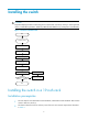
Step Description Plan the installation site and IRF fabric setup parameters: 1. Plan IRF fabric setup. • • • • • Planning IRF fabric size and the installation site Identifying the master switch and planning IRF member IDs Planning IRF topology and connections Identifying physical IRF ports on the member switches Planning the cabling scheme 2. Install IRF member switches. See "Installing the switch in a 19-inch rack". 3. Connect ground wires and power cords.
NOTE: IRF member switches will automatically elect a master. You can affect the election result by assigning a high member priority to the intended master switch. For more information about master election, see HP FlexFabric 5930 Switch Series IRF Configuration Guide. Prepare an IRF member ID assignment scheme. An IRF fabric uses member IDs to uniquely identify and manage its members, and you must assign each IRF member switch a unique member ID.
Figure 34 IRF fabric in ring topology Identifying physical IRF ports on the member switches Identify the QSFP+ ports to be used for IRF connections on the member switches according to your topology and connection scheme. All QSFP+ ports on the HP FlexFabric 5930 switch can be used for IRF connections. Planning the cabling scheme For the HP FlexFabric 5930 switches, use QSFP+ cables, or QSFP+ transceiver modules and fibers to connect the IRF member switches.
Figure 35 Connecting the switches in one rack 1 2 3 4 Figure 36 IRF fabric topology Connecting the IRF member switches in a ToR solution You can install IRF member switches in different racks side by side to deploy a top of rack (ToR) solution. Figure 37 shows an example for connecting four top of rack IRF member switches by using QSFP+ cables, and QSFP+ transceiver modules, and optical fibers. The topology is the same as Figure 36.
For more information about configuring basic IRF settings, see HP FlexFabric 5930 Switch Series IRF Configuration Guide. Connecting the physical IRF ports CAUTION: Wear an ESD-preventive wrist strap when you connect QSFP+ cables or QSFP+ transceiver modules and fibers. For more information, see QSFP+ Transceiver Modules/Cables Installation Guide. Use QSFP+ cables or QSFP+ transceiver modules and fibers to connect the IRF member switches as planned.
Maintenance and troubleshooting Power supply failure You can use the LEDs on the power supply to identify a power supply failure. For more information about the LEDs on a power supply, see HP A58x0AF 650W AC (JC680A) & 650W DC (JC681A) Power Supplies User Guide. The LEDs on the power supply are steady green (active) or flashing green (standby) while the power supply system is correctly operating.
• The power supply is supplying power to the switch. • The console cable is correctly connected. • The console cable has no problem and the terminal settings are correct.
Support and other resources Contacting HP For worldwide technical support information, see the HP support website: http://www.hp.
Conventions This section describes the conventions used in this documentation set. Command conventions Convention Description Boldface Bold text represents commands and keywords that you enter literally as shown. Italic Italic text represents arguments that you replace with actual values. [] Square brackets enclose syntax choices (keywords or arguments) that are optional. { x | y | ... } Braces enclose a set of required syntax choices separated by vertical bars, from which you select one.
Network topology icons Represents a generic network device, such as a router, switch, or firewall. Represents a routing-capable device, such as a router or Layer 3 switch. Represents a generic switch, such as a Layer 2 or Layer 3 switch, or a router that supports Layer 2 forwarding and other Layer 2 features. Port numbering in examples The port numbers in this document are for illustration only and might be unavailable on your device.
Appendix A Chassis views and technical specifications Chassis views Figure 38 HP FlexFabric 5930-32QSFP+/HP FlexFabric 5930-32QSFP+ TAA front panel (1) QSFP+ port (2) QSFP+ port LED (3) System status LED (SYS) Figure 39 HP FlexFabric 5930-32QSFP+/HP FlexFabric 5930-32QSFP+ TAA rear panel (1) Grounding screw (auxiliary grounding point 2) (2) Management Ethernet port (3) Serial console port (4) Fan tray slot 1 (5) Fan tray slot 2 (6) Power supply slot 1 (7) Power supply slot 2 (8) USB port (9) US
Figure 40 HP FlexFabric 5930-32QSFP+/HP FlexFabric 5930-32QSFP+ TAA left side panel (1) Primary grounding point (2) Auxiliary grounding point 1 Technical specifications Table 6 Technical specifications Item HP FlexFabric 5930-32QSFP+/HP FlexFabric 5930-32QSFP+ TAA Dimensions (H × W × D) 43.6 × 440 × 660 mm (1.72 × 17.32 × 25.98 in) Weight ≤ 13 kg (28.
Item HP FlexFabric 5930-32QSFP+/HP FlexFabric 5930-32QSFP+ TAA Operating temperature 0°C to 45°C (32°F to 113°F) Operating humidity 10% to 90%, noncondensing Fire resistance compliance UL60950-1, EN60950-1, IEC60950-1, GB4943 41
Appendix B FRUs and compatibility matrixes This appendix describes the field replaceable units (FRUs) available for the HP FlexFabric 5930 switches and their compatibility. All the FRUs in this appendix are hot swappable.
Item Specifications Fan speed 21000 R.P.M Max airflow 70 CFM Airflow direction Front to back (Fans draw air from the network port side to the power supply side.
Appendix C Ports and LEDs Ports Console port Every HP FlexFabric 5930 switch has two console ports: serial console port and Mini USB console port. Table 7 Console port specifications Item Console port Mini USB console port Connector type RJ-45 USB mini-Type B Compliant standard EIA/TIA-232 USB 2.0 Transmission baud rate 9600 bps (default) to 115200 bps • Provides connection to an ASCII terminal.
USB port Every HP FlexFabric 5930-32QSFP+/HP FlexFabric 5930-32QSFP+ TAA switch has one OHC-compliant USB2.0 port that can upload and download data at a rate up to 480 Mbps. You can use this USB port to access the file system on the Flash of the switch, for example, to upload or download application and configuration files. IMPORTANT: HP cannot make sure all USB devices from other vendors can be used on the switch, because of compatibility and driver differences.
Product code Cable description Cable length JG331A HP X240 40G QSFP+ to 4x10G SFP+ 5m Direct Attach Copper Splitter Cable 5 m (16.40 ft) Figure 41 40G QSFP+ cable 1 2 (1) Connector (2) Pull latch Figure 42 40G QSFP+ to 4x10G SFP+ cable (1) QSFP+ module (2) QSFP+ side pull latch (3) SFP+ side pull latch (4) SFP+ module NOTE: • To guarantee the functionality of the QSFP+ ports, use only HP QSFP+ transceiver modules and cables.
Table 11 System status LED description LED mark SYS Status Description Steady green The switch is operating correctly. Flashing green The switch is performing power-on self test (POST). Steady red The system has failed to pass POST or has problems such as fan failure. Flashing red Some ports have failed to pass POST. Off The switch is powered off or has failed to start up. QSFP+ port LED Each QSFP+ port has a status LED to show port operating status and activities.
Appendix D Cooling system The cooling system of the HP FlexFabric 5930 switches comprises the ventilation holes in the chassis, fan trays, and built-in fans of hot swappable power supplies. To guarantee that this cooling system can effectively work, you must consider the site ventilation design when you plan the installation site for the switches. The fan trays in the HP FlexFabric 5930-32QSFP+/HP FlexFabric 5930-32QSFP+ TAA switch must be the same type: LSWM1HFANSC or LSWM1HFANSCB.
Figure 44 Airflow through the HP FlexFabric 5930-32QSFP+/HP FlexFabric 5930-32QSFP+ TAA chassis (with LSWM1HFANSCB fan trays) (1) Power supply air vents (2) Fan tray air vents (3) Network port-side air vents IMPORTANT: The chassis and the power supplies use separate air aisles. Make sure both aisles are not blocked.
Index ACEFGHILPRSTV Installing the switch in a 19-inch rack,6 A Installing/removing a fan tray,14 Accessing the IRF fabric to verify the configuration,33 Installing/removing a power supply,16 C IRF fabric setup flowchart,28 Chassis views,39 L Configuration terminal problems,34 LEDs,46 Configuring basic IRF settings,32 Connecting the console cable,21 P Connecting the physical IRF ports,33 Planning IRF fabric setup,29 Connecting the power cord,19 Ports,44 Contacting HP,36 Power supply failur