HP FlexFabric 5930 Switch Series Fundamentals Configuration Guide Part number: 5998-4565 Software version: Release 2406 & Release 2407P01 Document version: 6W101-20140404
Legal and notice information © Copyright 2014 Hewlett-Packard Development Company, L.P. No part of this documentation may be reproduced or transmitted in any form or by any means without prior written consent of Hewlett-Packard Development Company, L.P. The information contained herein is subject to change without notice.
Contents Using the CLI ································································································································································ 1 CLI views ············································································································································································ 1 Entering system view from user view ·········································································································
Controlling user access ·············································································································································· 42 Controlling Telnet/SSH logins ······································································································································ 42 Configuration procedures ····································································································································· 42 Configuratio
Changing to another user account ······················································································································ 78 Maintaining and troubleshooting the FTP connection ······················································································· 78 Terminating the FTP connection ··························································································································· 79 Displaying command help information ·····················
Displaying and maintaining configuration files ········································································································ 100 Upgrading software ················································································································································ 101 Overview······································································································································································· 101 Softwar
Using automatic configuration ······························································································································· 127 Understanding automatic configuration ···················································································································· 127 Overall automatic configuration process ·········································································································· 127 Interface selection process·············
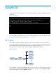
Using the CLI At the command-line interface (CLI), you can enter text commands to configure, manage, and monitor your device. Figure 1 CLI example You can use different methods to log in to the CLI, including through the console port, Telnet, and SSH. For more information about login methods, see "Login overview." CLI views Commands are grouped in different views by function. To use a command, you must enter its view. CLI views are hierarchically organized, as shown in Figure 2.
In user view, you can perform basic operations including display, debug, file management, FTP, Telnet, clock setting, and reboot. From user view, you can enter system view to configure global settings (such as the daylight saving time, banners, and hotkeys) and some functions. The system view prompt is [Device-name]. From system view, you can enter different function views.
• Enter a space and a question mark after a command keyword to display all available, subsequent keywords and arguments. { If the question mark is in the place of a keyword, the CLI displays all possible keywords, each with a brief description.
Table 1 Command line editing keys Keys Function Common keys If the edit buffer is not full, pressing a common key inserts a character at the position of the cursor and moves the cursor to the right. The edit buffer can store up to 511 characters. Unless the buffer is full, all common characters that you enter before pressing Enter are saved in the edit buffer. Backspace Deletes the character to the left of the cursor and moves the cursor back one character.
Usage guidelines • After you successfully execute a command by using a keyword alias, the system saves the keyword, instead of its alias, to the running configuration. • If a string you entered for a command partially matches an alias and a keyword, the command indicated by the alias is executed. To execute the command indicated by the keyword, enter the complete keyword. • If a string you entered for a command partially matches multiple aliases, the system displays an error message.
Step 3. (Optional.) Display hotkeys. Command Remarks display hotkey Available in any view. Table 2 System-reserved hotkeys Hotkey Function Ctrl+A Moves the cursor to the beginning of a line. Ctrl+B Moves the cursor one character to the left. Ctrl+C Stops the current command. Ctrl+D Deletes the character at the cursor. Ctrl+E Moves the cursor to the end of a line. Ctrl+F Moves the cursor one character to the right. Ctrl+H Deletes the character to the left of the cursor.
Step 2. Command Enable redisplaying entered-but-not-submit ted commands. Remarks By default, the system does not redisplay entered-but-not-submitted commands. info-center synchronous For more information about this command, see Network Management and Monitoring Command Reference. Understanding command-line error messages After you press Enter to submit a command, the command line interpreter examines the command syntax. If the command passes syntax check, the CLI executes the command.
Item Command history buffer for a user line Command history buffer for all user lines • In Windows 200x or Windows XP How to call buffered commands? HyperTerminal or Telnet, use the up or down arrow key (↑ or ↓) to navigate to a command in the buffer and press Enter to execute the command again. You cannot call buffered commands. • In Windows 9x HyperTerminal, use Ctrl+P and Ctrl+N to do so.
Keys Function Ctrl+C Stops the display and cancels the command execution. Displays the previous page. Displays the next page. Disabling pausing between screens of output To disable pausing between screens of output, execute the following command in user view: Task Disable pausing between screens of output for the current session. Command Remarks screen-length disable The default for a session depends on the setting of the screen-length command in user line view.
Filtering the output from a display command You can use the | { begin | exclude | include } regular-expression option to filter the display command output: • begin—Displays the first line matching the specified regular expression and all subsequent lines. • exclude—Displays all lines not matching the specified regular expression. • include—Displays all lines matching the specified regular expression.
Characters Meaning Examples {n} Matches the preceding character n times. The number n must be a nonnegative integer. "o{2}" matches "food", but not "Bob". {n,} Matches the preceding character n times or more. The number n must be a nonnegative integer. "o{2,}" matches "foooood", but not "Bob". {n,m} Matches the preceding character n to m times or more. The numbers n and m must be nonnegative integers and n cannot be greater than m. " o{1,3}" matches "fod", "food", and "foooood", but not "fd".
user-role network-admin # line vty 0 63 authentication-mode scheme user-role network-operator # ssh server enable # return # Use | exclude Direct in the display ip routing-table command to filter out direct routes and display only the non-direct routes. display ip routing-table | exclude Direct Destinations : 12 Routes : 12 Destination/Mask Proto Pre Cost NextHop Interface 2.2.2.0/24 OSPF 10 2 1.1.2.
# Verify whether the VLAN 1 settings are saved to file vlan.txt. more vlan.txt VLAN ID: 1 VLAN type: Static Route interface: Not configured Description: VLAN 0001 Name: VLAN 0001 Tagged ports: None Untagged ports: FortyGigE1/0/2 # Append the VLAN 999 settings to the end of file vlan.txt. display vlan 999 >> vlan.txt # Verify whether the VLAN 999 settings are appended to the end of file vlan.txt. more vlan.
Task Command View and manage the output from a display command effectively. display command [ | [ by-linenum ] { begin | exclude | include } regular-expression ] [ > filename | >> filename ] For example: # Save the running configuration to a separate file named test.txt, with each line numbered. display current-configuration | by-linenum > test.txt # Append lines including "snmp" in the running configuration to the file test.txt. display current-configuration | include snmp >> test.
Login overview The first time you access the device, you can log in to the CLI through the console port. After login, you can change console login parameters or configure other access methods, including Telnet, SSH, modem, and SNMP.
Logging in through the console port for the first device access The first time you access the device, you can only log in to the CLI through the console port. To log in through the console port, prepare a console terminal (for example, a PC) and make sure the console terminal has a terminal emulation program, for example, HyperTerminal in Windows XP. To log in through the console port: 1. Connect the DB-9 female connector of the console cable to the serial port of the PC. 2.
e. Select System Tools > Device Manager from the navigation tree. f. Select Ports (COM & LPT) from the right pane.
Figure 6 Setting the properties of the serial port 5. Power on the device and press Enter as prompted. Figure 7 Device CLI 6. At the default user view prompt , enter commands to configure the device or to view the running status of the device. To get help, enter ?.
Logging in to the CLI By default, you can log in to the CLI through the console port. After you log in, you can configure other login methods, including Telnet, SSH, and modem dial-in. To prevent illegal access to the CLI and control user behavior, you can configure login authentication, assign user roles, configure command authorization and command accounting, and use ACLs to filter unauthorized logins.
A relative number uniquely identifies a user line among all user lines that are the same type. The number format is user line type + number. All the types of user lines are numbered starting from 0 and incrementing by 1. For example, the first VTY line is VTY 0. Login authentication modes You can configure login authentication to prevent illegal access to the device CLI. The device supports the following login authentication modes: • None—Disables authentication.
Figure 8 Logging in through the console port By default, console login is enabled and does not require authentication. To improve device security, configure the password or scheme authentication mode and assign user roles immediately after you log in to the device for the first time. To configure console login, complete the following tasks: Task Remarks (Required.
Configuring password authentication for console login Step 1. Enter system view. Command Remarks system-view N/A Use either command. A setting in user line view is applied only to the user line. A setting in user line class view is applied to all user lines of the class. A non-default setting in either view takes precedence over a default setting in the other view. A non-default setting in user line view takes precedence over a non-default setting in user line class view. • To enter AUX line view: 2.
Step Command Remarks Use either command. A setting in user line view is applied only to the user line. A setting in user line class view is applied to all user lines of the class. • To enter AUX line view: Enter AUX line view or class view. 2. line aux first-number [ last-number ] • To enter AUX line class view: line class aux Enable scheme authentication. 3. A non-default setting in either view takes precedence over a default setting in the other view.
Step Command Remarks Use either command. A setting in user line view is applied only to the user line. A setting in user line class view is applied to all user lines of the class. • To enter AUX line view: 2. Enter AUX line view or class view. line aux first-number [ last-number ] • To enter AUX line class view: line class aux A non-default setting in either view takes precedence over a default setting in the other view.
Step Command Remarks By default, the terminal display type is ANSI. 10. Specify the terminal display type. terminal type { ansi | vt100 } 11. Set the maximum number of lines to be displayed on a screen. screen-length screen-length 12. Set the size of the command history buffer. history-command max-size value The device supports two terminal display types: ANSI and VT100. HP recommends that you set the display type to VT100 on both the device and the configuration terminal.
The Telnet login configuration is effective only for users who log in after the configuration is completed. Disabling authentication for Telnet login Step Command Remarks 1. Enter system view. system-view N/A 2. Enable Telnet server. telnet server enable By default, the Telnet server function is disabled. Use either command. A setting in user line view is applied only to the user line. A setting in user line class view is applied to all user lines of the class. • To enter VTY line view: 3.
Figure 9 Telnetting to the device without authentication Configuring password authentication for Telnet login Step Command Remarks 1. Enter system view. system-view N/A 2. Enable Telnet server. telnet server enable By default, the Telnet server function is disabled. Use either command. A setting in user line view is applied only to the user line. A setting in user line class view is applied to all user lines of the class. • To enter VTY line view: 3. Enter VTY line view or class view.
Step Command Remarks By default, password authentication is enabled for VTY lines. In VTY line view, this command is associated with the protocol inbound command: 4. Enable password authentication. authentication-mode password • If the setting of either command is not the default in VTY line view, the setting of the other command in VTY line view takes effect. • If the settings of both commands are the defaults in VTY line view, the settings of the commands in VTY line class view take effect. 5.
Step Command Remarks Use either command. A setting in user line view is applied only to the user line. A setting in user line class view is applied to all user lines of the class. • To enter VTY line view: 3. Enter VTY line view or class view. line vty first-number [ last-number ] • To enter VTY line class view: line class vty A non-default setting in either view takes precedence over a default setting in the other view.
Figure 11 Scheme authentication interface for Telnet login Setting the maximum number of concurrent Telnet users Step 1. Enter system view. Command Remarks system-view N/A By default, the maximum number of concurrent Telnet users is 16. 2. Set the maximum number of concurrent Telnet users. aaa session-limit telnet max-sessions Changing this setting does not affect online users.
Typically, you configure the auto-execute command telnet X.X.X.X command on the device so the device redirects a Telnet user to the host at X.X.X.X. In this case, the connection to the current device is closed when the user terminates the Telnet connection to X.X.X.X. To configure common settings for VTY lines: Step 1. Enter system view. Command Remarks system-view N/A Use either command. • To enter VTY line view: 2. Enter VTY line view or class view.
Step Command Remarks By default, the session idle timeout is 10 minutes for all user lines. 9. Set the session idle timeout. idle-timeout minutes [ seconds ] If there is no interaction between the device and the user within the idle timeout, the system automatically terminates the user connection on the user line. If you set the idle timeout to 0, the session will not be aged out. 10. Specify a command to be automatically executed when users log in to the user lines.
Logging in through SSH SSH offers a secure method to remote login. By providing encryption and strong authentication, it protects devices against attacks such as IP spoofing and plain text password interception. For more information, see Security Configuration Guide. You can use an SSH client to log in to the device for remote management, or use the device as an SSH client to log in to an SSH server. By default, SSH login is disabled on the device.
Step Command Remarks Password authentication is enabled for VTY lines by default. In VTY line view, this command is associated with the protocol inbound command: 6. Enable scheme authentication. • If the setting of either command is not the authentication-mode scheme default in VTY line view, the setting of the other command in VTY line view takes effect. • If the settings of both commands are the defaults in VTY line view, the settings of the commands in VTY line class view take effect.
Figure 13 Logging in to an SSH client from the device Perform the following tasks in user view: Task Command Log in to an IPv4 SSH server. ssh2 server Log in to an IPv6 SSH server. ssh2 ipv6 server To work with the SSH server, you might need to configure the SSH client. For information about configuring the SSH client, see Security Configuration Guide.
NOTE: The configuration commands and output vary by modem. For more information, see the modem user guide. 5. To ensure successful communication and to avoid data loss, verify that the modems use a transmission rate that is higher than the baud rate of the console port. 6. Launch the terminal emulation program on the PC and create a connection using the telephone number of the device-side modem. Figure 15 through Figure 18 show the configuration procedure in Windows XP HyperTerminal.
Figure 16 Configuring the dialing parameters 7. Dial the telephone number to establish a connection to the device. Figure 17 Dialing the number 8. After you hear the dial tone, press Enter as prompted. If the authentication mode is none, the prompt appears. If the authentication mode is password or scheme, you must enter the correct authentication information as prompted.
Figure 18 Login page IMPORTANT: Do not directly close the HyperTerminal. Doing so can cause some modems to stay in use, and your subsequent dial-in attempts will always fail. To disconnect the PC from the device, execute the appropriate ATH command in the HyperTerminal. If the command cannot be entered, type AT+ + + and press Enter, and when the word OK appears, execute the ATH command. The connection is terminated if OK is displayed.
Task Release a user line. Command Remarks free line { num1 | { aux | vty } num2 } Multiple users can log in to the device to simultaneously configure the device. When necessary, you can execute this command to release some connections. You cannot use this command to release the connection you are using. Lock the current user line. lock By default, the system does not lock any user line. Send messages to user lines. send { all | num1 | { aux | vty } num2 } Use this command in user view.
Accessing the device through SNMP You can run SNMP on an NMS to access the device MIB and perform Get and Set operations to manage and monitor the device. Figure 19 SNMP access diagram Get/Set requests NMS Get/Set responses and Traps MIB Agent The device supports SNMPv1, SNMPv2c, and SNMPv3, and can work with various network management software products, including IMC. However, the device and the NMS must use the same SNMP version.
Step 5. Create an SNMPv3 user. Command Remarks snmp-agent usm-user v3 user-name group-name [ remote { ip-address | ipv6 ipv6-address } [ vpn-instance vpn-instance-name ] ] [ { cipher | simple } authentication-mode { md5 | sha } auth-password [ privacy-mode { aes128 | des56 } priv-password ] ] [ acl acl-number | acl ipv6 ipv6-acl-number ] * To send informs to an SNMPv3 NMS, you must use the remote ip-address option to specify the IP address of the NMS.
Controlling user access Use ACLs to prevent unauthorized access and configure command authorization and accounting to monitor and control user behavior. For more information about ACLs, see ACL and QoS Configuration Guide. Controlling Telnet/SSH logins Use basic ACLs (2000 to 2999) to filter Telnet and SSH logins by source IP address. Use advanced ACLs (3000 to 3999) to filter Telnet and SSH logins by source and/or destination IP address.
Figure 20 Network diagram Configuration procedure # Configure an ACL to permit packets sourced from Host A and Host B. system-view [Sysname] acl number 2000 match-order config [Sysname-acl-basic-2000] rule 1 permit source 10.110.100.52 0 [Sysname-acl-basic-2000] rule 2 permit source 10.110.100.46 0 [Sysname-acl-basic-2000] quit # Apply the ACL to filter Telnet logins.
Step Command Remarks • SNMP community: snmp-agent community { read | write } [ simple | cipher ] community-name [ mib-view view-name ] [ acl acl-number | acl ipv6 ipv6-acl-number ] * • SNMPv1/v2c group: snmp-agent group { v1 | v2c } group-name [ read-view view-name ] [ write-view view-name ] [ notify-view view-name ] [ acl acl-number | acl ipv6 ipv6-acl-number ] * • SNMPv3 group: 2. Apply the ACL to an SNMP community, group, or user.
Figure 21 Network diagram Configuration procedure # Create an ACL to permit packets sourced from Host A and Host B. system-view [Sysname] acl number 2000 match-order config [Sysname-acl-basic-2000] rule 1 permit source 10.110.100.52 0 [Sysname-acl-basic-2000] rule 2 permit source 10.110.100.46 0 [Sysname-acl-basic-2000] quit # Associate the ACL with the SNMP community and the SNMP group.
Step Command Remarks Use either command. A setting in user line view is applied only to the user line. A setting in user line class view is applied to all user lines of the class. • To enter user line view: 2. line { first-number1 [ last-number1 ] | { aux | vty } first-number2 [ last-number2 ] } Enter user line view or user line class view. • To enter user line class view: line class { aux | vty } A non-default setting in either view takes precedence over a default setting in the other view.
Figure 22 Network diagram Configuration procedure # Assign IP addresses to relevant interfaces and make sure the device and the HWTACACS server can reach each other and the device and Host A can reach each other. (Details not shown.) # Enable the Telnet server. system-view [Device] telnet server enable # Enable scheme authentication for user lines VTY 0 through VTY 4. [Device] line vty 0 4 [Device-line-vty0-4] authentication-mode scheme # Enable command authorization for the user lines.
[Device-luser-admin] password cipher 123 [Device-luser-admin] service-type telnet [Device-luser-admin] authorization-attribute user-role level-1 Configuring command accounting Command accounting allows the HWTACACS server to record all executed commands that are supported by the device, regardless of the command execution result. This function helps control and monitor user behavior on the device. When command accounting is disabled, the accounting server does not record the commands executed by users.
Step Command Remarks By default, authentication is disabled for AUX lines, and password authentication is enabled for VTY lines. 3. Enable scheme authentication. In VTY line view, this command is associated with the protocol inbound command: authentication-mode scheme • If the setting of either command is not the default in VTY line view, the setting of the other command in VTY line view takes effect.
Figure 23 Network diagram Configuration procedure # Enable the Telnet server. system-view [Device] telnet server enable # Enable command accounting for user line AUX 0. [Device] line aux 0 [Device-line-aux0] command accounting [Device-line-aux0] quit # Enable command accounting for user lines VTY 0 through VTY 63. [Device] line vty 0 63 [Device-line-vty0-63] command accounting [Device-line-vty0-63] quit # Configure an HWTACACS scheme that does the following: • Uses the HWTACACS server at 192.
[Device-isp-system] quit 51
Configuring RBAC Role based access control (RBAC) controls user access to commands and resources based on user role. This chapter describes the basic idea of RBAC and guides you through the RBAC configuration procedure. Overview On devices that support multiple users, RBAC is used to assign command and resource access permissions to user roles that are created for different job functions. Users are given permission to access a set of commands and resources based on their user roles.
A user role can have multiple rules uniquely identified by rule numbers. The set of permitted commands in these rules are accessible to the user role. If two rules conflict, the one with higher number takes effect. For example, if rule 1 permits the ping command, rule 2 permits the tracert command, and rule 3 denies the ping command, the user role can use the tracert command but not the ping command.
User role name Permissions • level-0—Has access to diagnostic commands, including ping, quit, ssh2, super, system-view, telnet, and tracert. Level-0 access rights are configurable. • level-1—Has access to the display commands (except display history-command all) of all features and resources in the system, in addition to all access rights of the user role level-0. Level-1 access rights are configurable. • level-2 to level-8, and level-10 to level-14—Have no access rights by default.
Configuration task list Tasks at a glance (Required.) Creating user roles (Required.) Configuring user role rules (Optional.) Configuring feature groups (Optional.) Changing resource access policies (Optional.) Assigning user roles (Optional.) Configuring temporary user role authorization Creating user roles In addition to the predefined user roles, you can create up to 64 custom user roles for granular access control. To create a user role: Step 1. Enter system view.
Step 2. Enter user role view. Command Remarks role name role-name N/A Configure at least one command. • Configure a command rule: By default, a user-defined user role has no rules or access to any command. rule number { deny | permit } command command-string • Configure a feature rule: 3. Repeat this step to add up to 256 rules to the user role. rule number { deny | permit } { execute | read | write } * feature [ feature-name ] Configure a rule.
Changing the interface policy of a user role Step Command Remarks 1. Enter system view. system-view N/A 2. Enter user role view. role name role-name N/A interface policy deny By default, the interface policies of user roles permit access to all interfaces. 3. 4. Enter user role interface policy view. (Optional.) Specify a list of interfaces accessible to the user role. This command disables the access of the user role to any interface.
Assigning user roles To control user access to the system, you must assign at least one user role. Make sure at least one user role among the user roles assigned by the server exists on the device. User role assignment procedure varies with remote AAA authentication users, local AAA authentication users, and non-AAA authentication users (see "Assigning user roles"). For more information about AAA authentication, see Security Configuration Guide.
Step Create a local user and enter local user view. 2. Authorize the user to have a user role. 3. Command Remarks local-user user-name class { manage | network } N/A authorization-attribute user-role role-name Repeat this step to assign the user to up to 64 user roles. By default, network-operator is assigned to local users created by a network-admin or level-15 user.
Configuration guidelines When you configure temporary user role authorization, follow these guidelines: • To enable users to obtain temporary user role authorization, you must configure user role authentication. Table 10 describes the available authentication modes and configuration requirements. • Local password authentication is available for all user roles, but remote AAA authentication is available only for level-n user roles.
Keywords Authentication mode Description scheme local Remote AAA authentication first, and then local password authentication (remote-then-local) Remote AAA authentication is performed first. If the HWTACACS or RADIUS server does not respond, or the remote AAA configuration on the device is invalid, local password authentication is performed. Configuring user role authentication Step Command Remarks 1. Enter system view. system-view N/A 2. Set an authentication mode.
RBAC configuration examples RBAC configuration example for local AAA authentication users Network requirements The switch in Figure 24 performs local AAA authentication for the Telnet user at 192.168.1.58. This Telnet user has the username user1@bbb and is assigned the user role role1. Configure role1 to have the following permissions: • Executes the read commands of any feature. • Configures no VLANs except VLANs 10 to 20.
[Switch-role-role1-vlanpolicy] permit vlan 10 to 20 [Switch-role-role1-vlanpolicy] quit [Switch-role-role1] quit # Create a management local user named user1 and enter its view. [Switch] local-user user1 class manage # Set a plaintext password aabbcc for the user. [Switch-luser-manage-user1] password simple aabbcc # Set the service type to Telnet. [Switch-luser-manage-user1] service-type telnet # Assign role1 to the user.
• Has no access to read commands of the feature acl. • Configures VLANs 1 to 20 and interfaces FortyGigE 1/0/1 to FortyGigE 1/0/7. The switch and the FreeRADIUS server use the shared key expert and authentication port 1812. The switch delivers usernames with their domain names to the server. Figure 25 Network diagram Configuration procedure Make sure the settings on the switch and the RADIUS server match. 1.
IMPORTANT: Because RADIUS user authorization information is piggybacked in authentication responses, the authentication and authorization methods must use the same RADIUS scheme. [Switch] domain bbb [Switch-isp-bbb] authentication login radius-scheme rad [Switch-isp-bbb] authorization login radius-scheme rad [Switch-isp-bbb] quit # Create the feature group fgroup1. [Switch] role feature-group name fgroup1 # Add the features arp and radius to the feature group.
Verifying the configuration # Telnet to the switch, and enter the username and password to access the switch. (Details not shown.) # Verify that you can use all commands available in ISP view. system-view [Switch] domain abc [Switch-isp-abc] authentication login radius-scheme abc [Switch-isp-abc] quit # Verify that you can use all read and write commands of the features radius and arp. Take radius as an example. [Switch] radius scheme rad [Switch-radius-rad] primary authentication 2.2.2.
Figure 26 Network diagram Configuration procedure 1. Configure the switch: # Assign an IP address to VLAN-interface 2, the interface connected to the Telnet user. system-view [Switch] interface vlan-interface 2 [Switch-Vlan-interface2] ip address 192.168.1.70 255.255.255.0 [Switch-Vlan-interface2] quit # Assign an IP address to VLAN-interface 3, the interface connected to the HWTACACS server. [Switch] interface vlan-interface 3 [Switch-Vlan-interface3] ip address 10.1.1.2 255.255.255.
# Configure ISP domain bbb to use local authorization for login users. [Switch-isp-bbb] authorization login local # Apply the HWTACACS scheme hwtac to the ISP domain. [Switch-isp-bbb] authentication super hwtacacs-scheme hwtac [Switch-isp-bbb] quit # Create a management local user named test and enter its view. Set the service type to Telnet, and set the password to aabbcc.
Figure 27 Configuring advanced TACACS+ settings Verifying the configuration 1. Telnet to the switch, and enter the username test@bbb and password aabbcc to access the switch. Verify that you have access to diagnostic commands. telnet 192.168.1.70 Trying 192.168.1.70 ... Press CTRL+K to abort Connected to 192.168.1.59 ... ****************************************************************************** * Copyright (c) 2010-2013 Hewlett-Packard Development Company, L.P.
ssh2 Establish a secure shell client connection super Switch to a user role system-view Enter the System View telnet Establish a telnet connection tracert Tracert function 2. Obtain the level-3 user role: # Use the super password to obtain the level-3 user role. When the system prompts for a username and password, enter the username test@bbb and password enabpass.
Login attempts by RADIUS users always fail Symptom Attempts by a RADIUS user to log in to the network access device always fail, even though the network access device and the RADIUS server can communicate with one another and all AAA settings are correct. Analysis RBAC requires that a login user have at least one user role. If the RADIUS server does not authorize the login user to use any user role, the user cannot log in to the device.
Configuring FTP File Transfer Protocol (FTP) is an application layer protocol based on the client/server model. It is used to transfer files from one host to another over an IP network. FTP server uses TCP port 20 to transfer data and TCP port 21 to transfer control commands. For more information about FTP, see RFC 959. FTP supports the following transfer modes: • Binary mode—Used to transfer image files, such as .app, .bin, and .btm files. • ASCII mode—Used to transfer text files, such as .txt, .
Step Command Remarks The default idle-timeout interval is 30 minutes. 5. (Optional.) Configure the idle-timeout interval. ftp timeout minutes If no data is transferred between the FTP server and FTP client within the idle-timeout interval, the connection is terminated. • For an FTP server running 6. (Optional.) Set the DSCP value for outgoing FTP packets. IPv4: ftp server dscp dscp-value • For an FTP server running By default, the DSCP value is 0.
Manually releasing FTP connections Task Command • Release the FTP connection established using a specific user Manually release FTP connections. account: free ftp user username • Release the FTP connection to a specific IP address: free ftp user-ip [ ipv6 ] client-address [ port port-num ] Displaying and maintaining the FTP server Execute display commands in any view. Task Command Display FTP server configuration and status information.
[Sysname] ftp server enable [Sysname] quit # Examine the storage space for space insufficiency and delete unused files for more free space. dir Directory of flash: 0 -rw- 0 Sep 27 2010 14:43:34 kernel.bin 1 -rw- 0 Sep 27 2010 14:43:34 base.bin 2 drw- - Jun 29 2011 18:30:38 logfile 3 drw- - Jun 21 2011 14:51:38 diagfile 4 drw- - Jun 21 2011 14:51:38 seclog 5 -rw- 2943 Jul 02 2011 08:03:08 startup.cfg 6 -rw- 63901 Jul 02 2011 08:03:08 startup.
Step Command Remarks system-view N/A 1. Enter system view. 2. (Optional.) Specify a source IP address for outgoing FTP packets. ftp client source { interface interface-type interface-number | ip source-ip-address } By default, no source IP address is specified, and the primary IP address of the output interface is used as the source IP address. 3. Return to user view. quit N/A • (Method 1) Log in to the FTP server 4.
Managing directories on the FTP server Task Command • Display the detailed information of a directory or file Display directory and file information on the FTP server. on the FTP server: dir [ remotefile [ localfile ] ] • Display the name of a directory or file on the FTP server: ls [ remotefile [ localfile ] ] Change the working directory on the FTP server. cd { directory | .. | / } Return to the upper level directory on the FTP server. cdup Display the working directory that is being accessed.
Task Command Remarks Set the FTP operation mode to passive. passive The default mode is passive. Display or change the local working directory of the FTP client. lcd [ directory | / ] N/A Upload a file to the FTP server. put localfile [ remotefile ] N/A Download a file from the FTP server. get remotefile [ localfile ] N/A Add the content of a file on the FTP client to a file on the FTP server. append localfile [ remotefile ] N/A Specify the retransmit marker.
Task Command Remarks Enable or disable FTP operation information display. verbose By default, this function is enabled. Enable or disable FTP client debugging. debug By default, FTP client debugging is disabled. Clear the reply information in the buffer. reset N/A Terminating the FTP connection Task Command Remarks Terminate the connection to the FTP server without exiting FTP client view. • disconnect • close Use either command in FTP client view.
Figure 30 Network diagram Configuration procedure # Configure IP addresses as shown in Figure 30 and make sure the device and PC can reach each other. (Details not shown.) # Examine the storage space of the device. If the free space is insufficient, use the delete/unreserved file-url command to delete unused files. (Details not shown.) # Log in to the FTP server at 10.1.1.1 using the username abc and password 123456. ftp 10.1.1.1 Press CTRL+C to abort. Connected to 10.1.1.1 (10.1.1.1).
Configuring TFTP Trivial File Transfer Protocol (TFTP) is a simplified version of FTP for file transfer over secure reliable networks. TFTP uses UDP port 69 for data transmission. In contrast to TCP-based FTP, TFTP does not require authentication or complex message exchanges, and is easier to deploy. TFTP is suited for reliable network environments. The device can only operate as a TFTP client. You can upload a file from the device to the TFTP server or download a file from the TFTP server to the device.
Step Command Remarks (Optional.) Use an ACL to control the client's access to TFTP servers. tftp-server ipv6 acl acl-number By default, no ACL is used for access control. 3. Specify the source IPv6 address for TFTP packets sent by the TFTP client. tftp client ipv6 source { interface interface-type interface-number | ipv6 source-ip-address } By default, no source IPv6 address is specified. The source address is automatically selected as defined in RFC 3484. 4. Return to user view.
Managing the file system This chapter describes how to manage the device's file system, including the storage media, directories, and files. IMPORTANT: • Before managing storage media, files, and directories, make sure you know the possible impacts. • A file or directory whose name starts with a period (.) is considered a hidden file or directory. Do not give a common file or directory a name that starts with a period. • Some system files and directories are hidden.
Format Description Example Specifies a file in a specific storage medium on the device. drive:/[path]/file-name The drive argument represents the storage medium name. The storage medium on the device is typically flash or usb0. flash:/test/a.cfg indicates a file named a.cfg in the test folder in the root directory of the Flash memory. Managing files CAUTION: To avoid file system corruption, do not install or remove storage media during file operations.
Copying a file Perform this task in user view. Task Command Copy a file. copy fileurl-source fileurl-dest Moving a file Perform this task in user view. Task Command Move a file. move fileurl-source fileurl-dest Compressing/decompressing a file Perform the following tasks in user view: Task Command Compress a file. gzip filename Decompress a file. gunzip filename Deleting/restoring a file You can delete a file permanently or move it to the recycle bin.
A recycle bin is a folder named .trash in the root directory of the storage medium or partition. To view which files or directories are in a recycle bin, use either of the following methods: • Enter the storage medium or partition and execute the dir/all .trash command. • Execute the cd .trash command to enter the recycle bin folder and then execute the dir command. To delete files from a recycle bin, perform the following task in user view: Task Command Delete files from the recycle bin.
Changing the current working directory Perform this task in user view. Task Command Change the current working directory. cd { directory | .. | / } Creating a directory Perform this task in user view. Task Command Create a directory. mkdir directory Removing a directory To remove a directory, you must delete all files and subdirectories in this directory. To delete a file, use the delete command. To delete a subdirectory, use the rmdir command.
Before repairing a storage medium, make sure no other users are accessing the medium. Otherwise, the repair operation fails. Perform this task in user view. Task Command Repair a storage medium. fixdisk medium-name Formatting a storage medium CAUTION: After a storage medium is formatted, all files and directories on it are erased and cannot be restored. To format a storage medium that has been partitioned, you must format all the partitions individually, instead of formatting the medium as a whole.
Task Command Remarks Unmount a storage medium. umount medium-name By default, a storage medium is automatically mounted and in mounted state when connected to the system. Partitioning a USB disk A USB disk can be divided into logical devices called "partitions." Operations on one partition do not affect the other partitions. The following partitioning modes are available for USB disks: • Simple—Specify the number of partitions.
• alert—The system prompts for confirmation when your operation might cause problems such as file corruption and data loss. This mode provides an opportunity to cancel a disruptive operation. • quiet—The system does not prompt for confirmation. To set the operation mode for files and folders: Step Command Remarks 1. Enter system view. system-view N/A 2. Set the operation mode for files and folders. file prompt { alert | quiet } The default mode is alert.
Managing configuration files You can use the CLI or the Boot menu to manage configuration files. This chapter explains how to manage configuration files from the CLI. Overview A configuration file saves a set of commands for configuring software features on the device. You can save any configuration to a configuration file so they can survive a reboot. You can also back up configuration files to a host for future use.
To view the running configuration, use the display current-configuration command. The displayed configuration does not include parameters that use initial settings. Startup configuration loading process Figure 32 shows the configuration loading process during startup. Figure 32 Configuration loading process during startup The device uses the following process to select the startup configuration file to load at startup: 1.
c. If you have not specified a backup startup configuration file, or the specified backup startup configuration file is not available, the device starts up with the default configuration file (factory defaults). If a parameter is not included in the default configuration file, its initial setting is used. Configuration file formats Configuration files you specify for saving configuration must use the .cfg extension. A .cfg configuration file is a human-readable text file. When you save configuration to a .
Enabling configuration encryption Configuration encryption enables the device to encrypt a startup configuration file automatically when it saves the running configuration. This function provides the following methods: • Private key method—Any HP device running Comware V7 software can decrypt the encrypted configuration file. • Public key method—Any HP device can decrypt the encrypted configuration file. To enable configuration encryption: Step Command Remarks 1. Enter system view.
Task Command Remarks For reliable configuration saving, HP recommends that you specify the safely keyword. Save the running configuration to a configuration file and specify the file as a next-startup configuration file. save [ safely ] [ backup | main ] [ force ] If you execute the save [ safely ] command without specifying any other keyword, the command saves the configuration to the main startup configuration file.
Configuring configuration archive parameters Before archiving the running configuration, either manually or automatically, you must configure a file directory and file name prefix for configuration archives. Configuration archives are saved with the file name format prefix_serial number.cfg, for example, 20080620archive_1.cfg and 20080620archive_2.cfg. The serial number is automatically assigned from 1 to 1000, increasing by 1. After the serial number reaches 1000, it restarts from 1.
Step Enter system view. 1. Enable automatic configuration archiving and set the archiving interval. 2. Command Remarks system-view N/A By default, this function is disabled. To view configuration archive names and their archiving time, use the display archive configuration command.
• A command (for example, a hardware-dependent command) cannot be deleted, overwritten, or undone due to system restrictions. • The commands in different views are dependent on each other. • Commands or command settings that the device does not support cannot be added to the running configuration. Specifying a next-startup configuration file You can specify a .
Step Back up the next-startup configuration file to a TFTP server in user view. 2. Command Remarks backup startup-configuration to dest-addr [dest-filename ] N/A Restoring the main next-startup configuration file from a TFTP server To download a configuration file from a TFTP server to the root directory of the device's storage medium, and specify the file as the main next-startup configuration file, perform the task in this section.
Task Command Remarks Delete next-startup configuration files. reset saved-configuration [ backup | main ] If neither backup nor main is specified, this command deletes the main next-startup configuration file. Displaying and maintaining configuration files Execute display commands in any view. Task Command Display information about configuration rollback. display archive configuration Display the running configuration.
Upgrading software This chapter describes types of software and how to upgrade software from the CLI. For a comparison of all software upgrade methods, see "Upgrade methods." Overview Software upgrade enables you to have new features and fix bugs. Before performing an upgrade, use the release notes for the new software version to verify software and hardware compatibility and evaluate upgrade impacts. Software types The following software types are available: • Boot ROM image—A .
Comware image redundancy and loading procedure You can specify two sets of Comware software images: one main and one backup. The system always attempts to start up with the main images. If any main image does not exist or is invalid, the system tries the backup images. Figure 33 shows the entire Comware image loading procedure. This procedure assumes that the main image set and the backup image set have feature packages and patch packages.
Figure 34 System startup process Start Boot ROM runs Press Ctrl+B promptly? Enter Boot menus to upgrade Boot ROM or startup software images Yes No Startup software images run System starts up and CLI appears Finish Upgrade methods Upgrading method Software types Upgrading from the CLI • Boot ROM image • Comware images (excluding patches) Installing hotfixes Upgrading from the Boot menus Comware images • Boot ROM image • Comware software images Remarks This method is disruptive.
Preparing for the upgrade 1. Use the display version command to verify the current Boot ROM image version and startup software version. 2. Use the release notes for the upgrade software version to evaluate the upgrade impact on your network, and verify the following items: { Software and hardware compatibility { Version and size of the upgrade software { Compatibility of the upgrade software with the current Boot ROM image and startup software image 3.
Step Command Remarks Upgrade files must be saved in the root directory of the storage medium on the master device. • Method 1: boot-loader file ipe-filename slot slot-number { backup | main } 1. Specify main or backup startup image files for the master device. • Method 2: boot-loader file boot boot-package system system-package [ feature feature-package&<1-30> ] slot slot-number { backup | main } If the storage medium is partitioned, save the files to the root directory of the first partition.
Step 3. Commit the software change. Command Remarks install commit This command adds the patch image file to the main startup software image list. The committed patches continue to run after a reboot. Uninstalling patches Step 1. 2. Deactivate the patches installed from a patch image file. Commit the software change. Command Remarks install deactivate patch filename slot slot-number This command removes the patch image file from the current software image list.
Task Command Display current software images and startup software images. display boot-loader [ slot slot-number ] Display active software images. display install active [ slot slot-number ] [ verbose ] Display inactive software images. display install inactive [ slot slot-number ] [ verbose ] Display committed software images. display install committed [ slot slot-number ] [ verbose ] Display software image information.
display version Hotfix configuration example Network requirements Install patches to fix software bugs. Figure 36 Network diagram TFTP server TFTP client 1.1.1.1/24 Internet 2.2.2.2/24 Device Configuration procedure # Download the patch image file system-patch.bin from the TFTP server to the root directory of the flash memory. tftp 2.2.2.2 get system-patch.bin File will be transferred in binary mode Downloading file from remote TFTP server, please wait...
Managing the device This chapter describes how to monitor the operating status of the device, configure the running parameters (such as the device name, system time, and the temperature alarm thresholds), and reboot the device. You can perform the configuration tasks in this chapter in any order. Device management task list Tasks at a glance (Required.) Configuring the device name (Required.) Configuring the system time (Optional.) Enabling displaying the copyright statement (Optional.
Configuring the system time Specifying the system time source The device can use one of the following system time sources: • None—Local system time, which is manually configured at the CLI. • NTP—NTP time source. When the device uses the NTP time source, you cannot change the system time manually. For more information about NTP, see Network Management and Monitoring Configuration Guide.
Enabling displaying the copyright statement By default, the device displays the copyright statement when a Telnet or SSH user logs in, or when a console, or modem dial-in user quits user view. You can disable or enable the function as needed. The following is a sample copyright statement: ****************************************************************************** * Copyright (c) 2010-2013 Hewlett-Packard Development Company, L.P.
{ Method 1—Press Enter after the last command keyword. At the system prompt, enter the banner and end the last line with the delimiter character %. For example, you can configure the banner "Have a nice day. Please input the password." as follows: system-view [System] header shell Please input banner content, and quit with the character '%'. Have a nice day. Please input the password.
Setting the device operating mode The device can operate in the following modes: • advance—Advanced mode. • standard—Standard mode. To set the operating mode of the device: Step 1. 2. Command Remarks Enter system view. system-view N/A Set the operating mode. system-working-mode { advance | standard } By default, the device operates in standard mode. Change to the operating mode takes effect after a reboot. Setting the table mode The device supports multiple table modes.
Step 1. Enter system view. Command Remarks system-view N/A By default, the device operates in mode 0: • 288 KB MAC address table. • 16 KB ARP table or 8 KB ND table. • 16 KB IPv4 routing table or 8 KB IPv6 routing table. 2. Set the table mode. switch-mode { 0 | 1 | 2 | 3 | 4 } This command takes effect after a reboot. Before rebooting the device, make sure you know the possible impacts on the network and the required preparations are completed.
Task Command Remarks Reboot the device. reboot [slot slot-number ] [ force ] Use this command in user view Scheduling a device reboot The device supports only one device reboot schedule. If you configure the scheduler reboot at or scheduler reboot delay command multiple times or configure both commands, the most recent configuration takes effect. To schedule a reboot, execute either of the following commands in user view: Task Command Remarks Specify the reboot date and time.
Step Command Remarks By default, no command is assigned to a job. 3. Assign a command to the job. command id command You can assign multiple commands to a job. A command with a smaller ID will be executed first. 4. Exit system view. quit N/A 5. Create a schedule. scheduler schedule schedule-name By default, no schedule exists. 6. Assign a job to a schedule. By default, no job is assigned to a schedule. job job-name You can assign multiple jobs to a schedule.
Step Command Remarks • Execute the schedule at an interval 7. Specify an execution time table for the periodic schedule. from the specified time on: time repeating at time [ month-date [ month-day | last ] | week-day week-day&<1-7> ] • Execute the schedule at the specified time on every specified day in a month or week: time repeating [ at time [date ] ] interval interval-time Configure either command. By default, no execution time is specified for a schedule.
# Configure a job for disabling interface FortyGigE 1/0/2. [Sysname] scheduler job shutdown-FortyGigE1/0/2 [Sysname-job-shutdown-FortyGigE1/0/2] command 1 system-view [Sysname-job-shutdown-FortyGigE1/0/2] command 2 interface fortygige 1/0/2 [Sysname-job-shutdown-FortyGigE1/0/2] command 3 shutdown [Sysname-job-shutdown-FortyGigE1/0/2] quit # Configure a job for enabling interface FortyGigE 1/0/2.
# Display the schedule information.
Schedule name : STOP-pc1/pc2 Execution time : Wed Sep 28 18:00:00 2011 Completion time : Wed Sep 28 18:00:01 2011 --------------------------------- Job output ----------------------------------system-view System View: return to User View with Ctrl+Z.
Select the correct model and configure the preferred airflow direction to be consistent with the airflow direction of the ventilation system in the equipment room. You can configure the preferred airflow direction for the device. If a fan tray is not operating correctly or the device detects that an installed fan tray has a different airflow direction than the configured one, the system sends out logs. You must replace the wrong fan tray with a correct tray.
As shown in Table 14 and Figure 38, the system supports the following thresholds: • Normal state threshold. • Minor alarm threshold. • Severe alarm threshold. • Critical alarm threshold. Table 14 Memory alarm notifications and memory alarm-removed notifications Notification Triggering condition Remarks Minor alarm notification The amount of free memory space decreases to or below the minor alarm threshold for the first time.
To set memory usage thresholds: Step 1. Enter system view. Command Remarks system-view N/A The defaults are as follows: 2. Set memory usage thresholds. memory-threshold [ slot slot-number ] minor minor-value severe severe-value critical critical-value normal normal-value • • • • Minor alarm threshold—96 MB. Severe alarm threshold—64 MB. Critical alarm threshold—48 MB. Normal state threshold—128 MB.
Disabling all USB interfaces You can use USB interfaces to upload or download files. By default, all USB interfaces are enabled. You can disable USB interfaces as needed. To disable all USB interfaces: Step Enter system view. 1. Command Remarks system-view N/A By default, all USB interfaces are enabled. Disable all USB interfaces. 2. Before executing this command, use the umount command to unmount all USB partitions. For more information about this command, see Fundamentals Command Reference.
Task Command Remarks Display transceiver alarms. display transceiver alarm { interface [ interface-type interface-number ] } N/A Display the current values of the digital diagnosis parameters on transceiver modules. display transceiver diagnosis { interface [ interface-type interface-number ] } This command cannot display information about some transceiver modules. Restoring the factory-default settings and states CAUTION: This feature is disruptive.
Task Command Display historical CPU usage statistics in a chart. display cpu-usage history [ job job-id ] [ slot slot-number [ cpu cpu-number ] ] Display hardware information. display device [ usb ] [ slot slot-number [ subslot subslot-number ] | verbose ] Display the electronic label information of the device. display device manuinfo [ slot slot-number ] Display the electronic label information of a fan.
Using automatic configuration With the automatic configuration feature, the device can automatically obtain a set of configuration settings from some servers when it starts up without a configuration file. This feature simplifies network configuration, facilitates centralized management, and reduces maintenance workload.
configuration file, the device deletes its temporary settings, and waits 2 minutes before trying again for automatic configuration by selecting another qualified interface and repeating Step 2 to Step 4. To stop the automatic configuration process, press Ctrl+C at the CLI of the device. IMPORTANT: • To ensure quick and successful automatic configuration of a device, connect only the interface used for automatic configuration to the network. • The device does not save the obtained configuration file.
Figure 40 Automatic configuration workflow Device powered on (no configuration file) Select an interface Enable DHCP client and request parameters N Restore the default for the interface Got parameters? Y Y: HTTP method Got a configuration file name and the name is in the form of an HTTP URL? N: TFTP method N N Got the TFTP server IP address? Got the TFTP server domain name? Y Y Download the configuration file from the HTTP server Y N Resolved the TFTP server domain name? N Got the configura
3. If no Layer 2 Ethernet interface is in up state, the device sorts all Layer 3 Ethernet interfaces in up state first by the dictionary order of the interface types and then in ascending order of interface numbers, and selects the one with the smallest interface number among the interfaces of the first interface type.
• If the device did not get a configuration file name during the automatic-configuration parameter acquisition process, or if the device got a configuration file name that is not in the form of a valid HTTP URL, the device starts to acquire a configuration file from a TFTP server: { If the device has got a TFTP server IP address, it unicasts a request to the TFTP server. { If not, the device broadcasts a request. In this case, the device resolves only the first reply.
Deploying and configuring servers for automatic configuration To implement automatic configuration, you do not need to perform any configuration on the device.
After you complete the static binding configuration, ask the device administrator to power off the device and then power it on so the device gets the IP address and configuration parameters you configured for it. HTTP server configuration guidelines Create configuration files required for device automatic configuration on the HTTP server. For easy file name identification, use configuration file names that do not contain spaces.
Support and other resources Contacting HP For worldwide technical support information, see the HP support website: http://www.hp.
Conventions This section describes the conventions used in this documentation set. Command conventions Convention Description Boldface Bold text represents commands and keywords that you enter literally as shown. Italic Italic text represents arguments that you replace with actual values. [] Square brackets enclose syntax choices (keywords or arguments) that are optional. { x | y | ... } Braces enclose a set of required syntax choices separated by vertical bars, from which you select one.
Network topology icons Represents a generic network device, such as a router, switch, or firewall. Represents a routing-capable device, such as a router or Layer 3 switch. Represents a generic switch, such as a Layer 2 or Layer 3 switch, or a router that supports Layer 2 forwarding and other Layer 2 features. Represents an access controller, a unified wired-WLAN module, or the switching engine on a unified wired-WLAN switch. Represents an access point.
Index assigning A CLI user line assignment, 19 AAA RBAC local AAA authentication user role, 58 RBAC AAA authorization, 54 RBAC non-AAA authentication user role, 59 RBAC default user role function, 58 RBAC local AAA authentication user configuration, 62 RBAC user role local AAA authentication, 58 RBAC remote AAA authentication user role, 58 RBAC user role, 58 authenticating FTP basic server authentication, 73 RBAC user role non-AAA authentication, 59 login management CLI console none authentication
configuration.
string/text type argument value, 4 configuration archiving (automatic), 96 undo command form, 3 configuration rollback, 95, 97 use, 1 content, 93 user lines, 19 device configuration types, 91 user roles, 20 displaying, 100 view hierarchy, 1 encryption, 94 file formats, 93 client FTP client configuration (centralized device), 79 format, 93 IPv4 TFTP client configuration, 81 main next-startup file backup, 98 IPv6 TFTP client configuration, 81 main next-startup file restore, 99 management, 91
login management command authorization, 45, 46 login management common VTY line settings, 30 login management SNMP access control, 44 login management SNMPv1 access, 41 login management SNMPv2 access, 41 login management SNMPv3 access, 40 RBAC configuration, 52, 55 copying file, 85 copyright statement display, 111, 111 CPU device CPU usage monitoring, 121 creating file system directory, 87 login management SSH login, 33 login management SSH login on device, 33 login management Telnet login, 25 RBAC user
return to user view, 2 FTP client configuration (centralized device), 79 FTP client connection establishment, 75 running configuration, 91 FTP configuration, 72 software upgrade, 101 FTP connection termination, 79 startup configuration, 91 FTP connection troubleshooting, 78 startup configuration loading, 92 FTP manual server connection release, 74 storage media CF card partition, 89 FTP server, 72 storage media USB disk partition, 89 FTP server authentication, 73 system startup process, 102 F
device transceiver modules, 124, 124, 124, 124 private key, 94 directory file system current working directory change, 87 public key, 94 entering file system current working directory display, 86 CLI entered-but-not-submitted command redisplay, 6 file system directory creation, 87 command, 3 file system directory information display, 86 string/text type argument value, 4 file system directory management, 86 system view from user view, 2 file system directory removal, 87 error file system manag
directory removal, 87 displaying client, 79 file compression, 85 displaying server, 74 file copy, 85 IPv4 TFTP client configuration, 81 file decompression, 85 IPv6 TFTP client configuration, 81 file deletion, 85 local server authentication, 73 file digest calculation, 86 local server authorization, 73 file information display, 84 manual server connection release, 74 file management, 84 remote server authentication, 73 file move, 85 remote server authorization, 73 file name formats, 83 ser
software hotfix, 105 login management CLI login, 19 software patch, 105 login management CLI login authentication modes, 20 software patches, 105, 108 login management CLI user lines, 19 interface, 15, See also line login management CLI user roles, 20 IP login management console port login, 16 FTP configuration, 72 TFTP configuration, 81 login management modem login, 35 FTP client connection establishment, 75 TFTP client configuration, 81 login management SSH login configuration on device, 33
SNMPv2 access configuration, 41 device system operating mode, 113, 113 SNMPv3 access configuration, 40 device table mode, 113, 113 SSH login, 33 file system file/folder alert operation mode, 89 SSH login control, 42 file system file/folder quiet operation mode, 89 SSH login on device, 33 FTP active (PORT) operating mode, 72 SSH server login, 34 FTP ASCII transfer mode, 72 Telnet login, 25 FTP binary transfer mode, 72 Telnet login control, 42, 42 FTP passive (PASV) operating mode, 72 Telnet l
device banner input modes, 111, 111 login management SNMP access control, 43, 44 device banner types, 111, 111 login management SNMPv1 access configuration, 41 device copyright statement display, 111, 111 login management SNMPv2 access configuration, 41 device CPU usage monitoring, 121, 121 device factory-default settings and states, 125 login management SNMPv3 access configuration, 40 device management task scheduling, 115, 115, 117, 117 login management SSH login control, 42 device memory usage
storage media USB disk, 89 login management SNMP device access, 40 non-AAA authentication (RBAC), 59 passive none login management CLI authentication mode, 20 FTP passive (PASV) operating mode, 72 password login management CLI console none authentication, 21 device password recovery capability disable, 120, 120 login management Telnet login none authentication, 26 login management CLI authentication mode, 20 login management CLI console password authentication, 22 none-AAA authorization (RBAC), 54
configuring login management CLI console scheme authentication, 22 abbreviating CLI command, 4 accessing CLI online help, 2 configuring login management CLI local console port login, 20 assigning RBAC local AAA authentication user role, 58 assigning RBAC non-AAA authentication user role, 59 configuring login management command accounting, 48, 49 assigning RBAC remote AAA authentication user role, 58 configuring login management command authorization, 45, 46 configuring login management SNMP access con
deleting file from recycle bin, 85 maintaining device management configuration, 125, 125 deleting next-startup configuration file, 99 deleting software patch, 106 maintaining FTP connection, 78 diagnosing device transceiver module, 124, 124, 124, 124 managing CLI display command output, 13 disabling device USB interface, 124, 124 managing file system files, 84 disabling CLI console authentication, 21 managing file system storage media, 87 disabling CLI output screen pausing, 9 managing FTP server
setting login management Telnet login max number concurrent users, 30 temporary user role authorization configuration, 59 troubleshooting, 70 specifying device system time source, 110, 110 troubleshooting local user access permissions, 70 specifying next-startup configuration file, 98 specifying startup image file, 104 troubleshooting login attempts by RADIUS users fail, 71 terminating FTP connection, 79 user role assignment, 54, 58 troubleshooting FTP connection, 78 user role authentication, 61 t
FTP configuration, 72 login management user access control, 42 TFTP configuration, 81, 81 RBAC configuration, 52, 55, 62 RBAC default user role function, 58 rule file system storage media naming, 83 RBAC feature group configuration, 56 RBAC command rule, 52 RBAC HWTACACS authentication user configuration, 66 RBAC feature execute rule, 52 RBAC local AAA authentication user configuration, 62 RBAC feature group rule, 52 RBAC feature read rule, 52 RBAC permission assignment, 52 RBAC feature write ru
login management SNMPv3 access configuration, 40 login control, 42 SNMPv1 access configuration, 41 server login, 34 SNMPv2 access configuration, 41 SNMPv1 login management overview, 15 starting up Boot ROM image preload, 104 login management access configuration, 41 software upgrade procedure (CLI), 103 login management SNMP device access, 40 software upgrade with CLI method, 107 SNMPv2 startup image file specification, 104 login management access configuration, 41 login management SNMP device a
CLI command abbreviation, 4 device name configuration, 109, 109 CLI command entry, 3 CLI command history function use, 7 device password recovery capability disable, 120, 120 CLI command hotkey configuration, 5 device port status detection timer, 121, 121 CLI command hotkey use, 5 device reboot, 114, 114 CLI command keyword alias configuration, 4 device reboot (immediate), 114, 114 device reboot (scheduled), 115, 115 CLI command keyword alias use, 4 device system operating mode, 113, 113 CLI com
login management SNMP access control, 43, 44 login, 25 login management SSH login, 33 login device configuration, 25 login control, 42, 42 login management SSH login configuration on device, 33 login management overview, 15 login management SSH login control, 42 login none authentication, 26 login max number concurrent users, 30 login management SSH server login, 34 login password authentication, 27 login management Telnet login, 25 login scheme authentication, 28 login management Telnet login
software patch, 106 using CLI, 1 unmounting command history function, 7 file system storage media, 88 command hotkey, 5 upgrading software.