HP FlexFabric 5930 Switch Series High Availability Configuration Guide Part number: 5998-4567 Software version: Release 2406 & Release 2407P01 Document version: 6W101-20140404
Legal and notice information © Copyright 2014 Hewlett-Packard Development Company, L.P. No part of this documentation may be reproduced or transmitted in any form or by any means without prior written consent of Hewlett-Packard Development Company, L.P. The information contained herein is subject to change without notice.
Contents Configuring DLDP ························································································································································· 1 Overview············································································································································································ 1 Basic concepts ····································································································································
Multiple VRRP groups configuration example ···································································································· 35 IPv6 VRRP configuration examples ······························································································································· 38 Single VRRP group configuration example ········································································································· 38 Multiple VRRP groups configuration example ·········
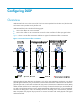
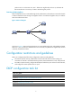
Configuring DLDP Overview Unidirectional links occur when one end of a link can receive packets from the other end, but the other end cannot receive packets sent by the first end. Unidirectional fiber links include the following types: • Occur when fibers are cross-connected. • Occur when a fiber is not connected at one end or when one fiber of a fiber pair gets broken. Figure 1 shows a correct fiber connection and the two types of unidirectional fiber connections.
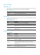
Basic concepts DLDP neighbor states If port A and B are on the same link and port A can receive link-layer packets from port B, port B is a DLDP neighbor of port A. Two ports that can exchange packets are neighbors. Table 1 DLDP neighbor states DLDP timer Description Confirmed The link to a DLDP neighbor is bidirectional. Unconfirmed The state of the link to a newly discovered neighbor is not determined. DLDP port states A DLDP-enabled port is called a "DLDP port.
DLDP timer DelayDown timer RecoverProbe timer Description If a port is physically down, the device triggers the DelayDown timer (the default is 1 second and is configurable), rather than removing the corresponding neighbor entry. When the DelayDown timer expires, the device removes the corresponding DLDP neighbor information if the port is down, and does not perform any operation if the port is up. This timer is set to 2 seconds.
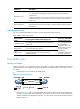
a. Port 1 receives the RecoverProbe packet from Port 4, and returns a RecoverEcho packet. b. Port 4 cannot receive any RecoverEcho packet from Port 1, so Port 4 cannot become the neighbor of Port 1. c. Port 3 can receive the RecoverEcho packet from Port 1, but Port 3 is not the intended destination, so Port 3 cannot become the neighbor of Port 1. The same process occurs on the other three ports. The four ports are all in Unidirectional state. • Unidirectional links occur after you enable DLDP.
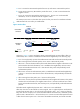
packet to Port 2. At the same time, Port 1 deletes the neighborship with Port 2, and starts the RecoverProbe timer. Port 2 stays in Inactive state during this process. Detecting multiple neighbors When multiple devices are connected through a hub, enable DLDP on all interfaces connected to the hub to detect unidirectional links among the neighbors. When no Confirmed neighbor exists, an interface enters the Unidirectional state.
Enabling DLDP To correctly configure DLDP on the device, you must enable DLDP globally and on each port. To enable DLDP: Step Command Remarks 1. Enter system view. system-view N/A 2. Enable DLDP globally. dldp global enable By default, DLDP is globally disabled. 3. Enter Layer 2 or Layer 3 Ethernet interface view. interface interface-type interface-number N/A 4. Enable DLDP. dldp enable By default, DLDP is disabled on an interface.
Setting the port shutdown mode On detecting a unidirectional link, the ports can be shut down in one of the following modes: • Auto mode—When a unidirectional link is detected, DLDP changes the DLDP port state to Unidirectional. The unidirectional port periodically sends RecoverProbe packets. When a correct RecoverEcho packet is received, the link is restored to a bidirectional link, and the port state changes from Unidirectional to Bidirectional. This process is called "link auto-recovery mechanism.
Task Command Display the DLDP configuration globally and of a port. display dldp [ interface interface-type interface-number ] Display the statistics on DLDP packets passing through a port. display dldp statistics [ interface interface-type interface-number ] Clear the statistics on DLDP packets passing through a port.
[DeviceA-FortyGigE1/0/2] dldp enable [DeviceA-FortyGigE1/0/2] quit # Set the port shutdown mode to auto. [DeviceA] dldp unidirectional-shutdown auto 2. Configure Device B: # Enable DLDP globally. system-view [DeviceB] dldp global enable # Configure FortyGigE 1/0/1 to operate in full duplex mode and at 40000 Mbps, and enable DLDP on it.
Neighbor MAC address: 0023-8956-3600 Neighbor port index: 2 Neighbor state: Confirmed Neighbor aged time: 12s The output shows that both FortyGigE 1/0/1 and FortyGigE 1/0/2 are in Bidirectional state, which means both links are bidirectional. # Enable the monitoring of logs on the current terminal on Device A, and set the lowest level of the logs that can be output to the current terminal to 6.
%Jul 11 17:42:57:709 2012 DeviceA IFNET/3/PHY_UPDOWN: FortyGigE1/0/1 link status is DOWN. %Jul 11 17:42:58:603 2012 DeviceA IFNET/3/PHY_UPDOWN: FortyGigE1/0/2 link status is DOWN. %Jul 11 17:43:02:342 2012 DeviceA IFNET/3/PHY_UPDOWN: FortyGigE1/0/1 link status is UP. %Jul 11 17:43:02:343 2012 DeviceA DLDP/6/DLDP_NEIGHBOR_CONFIRMED: A neighbor was confirmed on interface FortyGigE1/0/1. The neighbor's system MAC is 0023-8956-3600, and the port index is 1.
[DeviceA] interface fortygige 1/0/1 [DeviceA-FortyGigE1/0/1] duplex full [DeviceA-FortyGigE1/0/1] speed 40000 [DeviceA-FortyGigE1/0/1] dldp enable [DeviceA-FortyGigE1/0/1] quit # Configure FortyGigE 1/0/2 to operate in full duplex mode and at 40000 Mbps, and enable DLDP on the port. [DeviceA] interface fortygige 1/0/2 [DeviceA-FortyGigE1/0/2] duplex full [DeviceA-FortyGigE1/0/2] speed 40000 [DeviceA-FortyGigE1/0/2] dldp enable [DeviceA-FortyGigE1/0/2] quit # Set the port shutdown mode to manual.
Interface FortyGigE1/0/1 DLDP port state: Bidirectional Number of the port’s neighbors: 1 Neighbor MAC address: 0023-8956-3600 Neighbor port index: 1 Neighbor state: Confirmed Neighbor aged time: 11s Interface FortyGigE1/0/2 DLDP port state: Bidirectional Number of the port’s neighbors: 1 Neighbor MAC address: 0023-8956-3600 Neighbor port index: 2 Neighbor state: Confirmed Neighbor aged time: 12s The output shows that both FortyGigE 1/0/1 and FortyGigE 1/0/2 are in Bidirectional state, which means both li
Interface FortyGigE1/0/1 DLDP port state: Unidirectional Number of the port’s neighbors: 0 (Maximum number ever detected: 1) Interface FortyGigE1/0/2 DLDP port state: Unidirectional Number of the port’s neighbors: 0 (Maximum number ever detected: 1) The output shows that the DLDP port status of both FortyGigE 1/0/1 and FortyGigE 1/0/2 is unidirectional, which indicates that DLDP detects unidirectional links on them but does not shut down the two ports.
[DeviceA-FortyGigE1/0/2] quit [DeviceA] interface fortygige 1/0/1 [DeviceA-FortyGigE1/0/1] undo shutdown The following log information is displayed on Device A: [DeviceA-FortyGigE1/0/1]%Jul 12 08:48:25:952 2012 DeviceA IFNET/3/PHY_UPDOWN: FortyGigE1/0/1 link status is UP. %Jul 12 08:48:25:952 2012 DeviceA DLDP/6/DLDP_NEIGHBOR_CONFIRMED: A neighbor was confirmed on interface FortyGigE1/0/1. The neighbor's system MAC is 0023-8956-3600, and the port index is 1.
Configuring VRRP The interfaces that VRRP involves can be only Layer 3 Ethernet interfaces, VLAN interfaces, and Layer 3 aggregate interfaces unless otherwise specified. You can set an Ethernet port as a Layer 3 interface by using the port link-mode route command (see Layer 2—LAN Switching Configuration Guide). VRRP cannot be configured on member ports of aggregation groups. Overview Typically, you can configure a default gateway for every host on a LAN.
• Load balancing mode—Extends the VRRP standard mode to distribute load across VRRP group members. For more information, see "VRRP load balancing mode." VRRP has two versions: VRRPv2 and VRRPv3. VRRPv2 supports IPv4 VRRP. VRRPv3 supports IPv4 VRRP and IPv6 VRRP. VRRP standard mode In VRRP standard mode, only the master in the VRRP group can provide gateway service. When the master fails, the backup routers elect a new master to take over for nonstop gateway service.
• Preemptive mode—A backup starts a new master election and takes over as master when it detects that it has a higher priority than the current master. Preemptive mode makes sure the router with the highest priority in a VRRP group always acts as the master. Authentication method To avoid attacks from unauthorized users, VRRP member routers add authentication keys in VRRP packets to authenticate one another.
Master election Routers in a VRRP group determine their roles by priority. When a router joins a VRRP group, it has a backup role. The router role changes according to the following situations: • If the backup does not receive any VRRP advertisement when the timer (3 × advertisement interval + Skew_Time) expires, it becomes the master. • If the backup receives a VRRP advertisement with a greater or the same priority within the timer (3 × advertisement interval + Skew_Time), it remains a backup.
Load sharing A router can join multiple VRRP groups and has different priorities in different VRRP groups, and it can act as the master in one VRRP group and a backup in another. In load sharing mode, multiple VRRP groups provide gateway services. This mode requires at least two VRRP groups, and each group has one master and multiple backups. The master roles in the VRRP groups are assumed by different routers, as shown in Figure 10.
VRRP load balancing mode uses the same master election, and preemption mechanisms as the standard mode, and adds new mechanisms as described in the following sections. Virtual MAC address assignment In load balancing mode, the master assigns virtual MAC addresses to routers in the VRRP group and uses different MAC addresses to respond to ARP requests or ND requests from different hosts. The backup routers, however, do not answer ARP requests or ND requests from hosts.
Figure 12 Answering ARP requests 3. Each host sends packets to the returned MAC address. As shown in Figure 13, Host A sends packets to Router A and Host B sends packets to Router B. Figure 13 Sending packets to different routers for forwarding Virtual forwarder Virtual forwarder creation Virtual MAC addresses enable traffic distribution across routers in a VRRP group. To enable routers in the VRRP group to forward packets, VFs must be created on them.
1. The master assigns virtual MAC addresses to all routers in the VRRP group. Each member router creates a VF for this MAC address and becomes the owner of this VF. 2. Each VF owner advertises its VF information to the other member routers. 3. After receiving the VF advertisement, each of the other routers creates the advertised VF. Eventually, every member router maintains one VF for each virtual MAC address in the VRRP group.
Figure 14 shows the VF table on each router in the VRRP group and how the VFs back up one another. The master, Router A, assigns virtual MAC addresses 000f-e2ff-0011, 000f-e2ff-0012, and 000f-e2ff-0013 to itself, Router B, and Router C; and each router creates VF 1, VF 2, and VF 3, respectively, for the virtual MAC addresses. The VFs for the same virtual MAC address on different routers back up one another. For example, the VF 1 instances on Router A, Router B, and Router C back up one another.
Tasks at a glance Remarks (Required.) Creating a VRRP group and assigning a virtual IP address N/A (Optional.) Configuring the router priority and preemptive mode N/A (Optional.) Configuring IPv4 VRRP packet attributes N/A (Optional.) Enabling SNMP notifications for VRRP N/A (Optional.) Disabling an IPv4 VRRP group N/A Specifying an IPv4 VRRP operating mode A VRRP group can operate in either of the following modes: • Standard mode—Only the master can forward packets.
Configuration guidelines • In VRRP load balancing mode, the device supports a maximum of MaxVRNum/N VRRP groups. MaxVRNum refers to the maximum number of VRRP groups supported by the device in VRRP standard mode, and N refers to the number of devices in the VRRP group. • When VRRP is operating in standard mode, the virtual IP address of a VRRP group can be either an unused IP address on the subnet where the VRRP group resides or the IP address of an interface on a router in the VRRP group.
Step Command Remarks 1. Enter system view. system-view N/A 2. Enter interface view. interface interface-type interface-number N/A 3. Configure the priority of the router in the VRRP group. vrrp vrid virtual-router-id priority priority-value The default setting is 100. 4. Enable the preemptive mode for the router in a VRRP group and configure the preemption delay time.
Step Command Remarks 5. Specify the source interface for receiving and sending VRRP packets. vrrp vrid virtual-router-id source-interface interface-type interface-number By default, the source interface for receiving and sending VRRP packets is not specified. The interface where the VRRP group resides sends and receives VRRP packets. 6. Enable TTL check for IPv4 VRRP packets. vrrp check-ttl enable By default, TTL check for IPv4 VRRP packets is enabled. 7. Return to system view.
Displaying and maintaining IPv4 VRRP Execute display commands in any view and the reset command in user view. Task Command Display states of IPv4 VRRP groups. display vrrp [ interface interface-type interface-number [ vrid virtual-router-id ] ] [ verbose ] Display statistics for IPv4 VRRP groups. display vrrp statistics [ interface interface-type interface-number [ vrid virtual-router-id ] ] Clear statistics for IPv4 VRRP groups.
Step Command Remarks • Specify the standard mode: Specify an IPv6 VRRP operating mode. 2. undo vrrp ipv6 mode • Specify the load balancing mode: vrrp ipv6 mode load-balance Use one of the commands. By default, VRRP operates in standard mode. Creating a VRRP group and assigning a virtual IPv6 address A VRRP group can work correctly after you create it and assign at least one virtual IPv6 address for it.
Configuring the router priority and preemptive mode Configuration guidelines The running priority of an IP address owner is always 255, and you do not need to configure it. An IP address owner always operates in preemptive mode. Configuration procedure To configure the router priority and preemptive mode: Step Command Remarks 1. Enter system view. system-view N/A 2. Enter interface view. interface interface-type interface-number N/A 3. Configure the priority of the router in the VRRP group.
Step Command Remarks The default setting is 100 centiseconds. 3. Configure the IPv6 VRRP advertisement interval. vrrp ipv6 vrid virtual-router-id timer advertise adver-interval To maintain system stability, HP recommends that you set the VRRP advertisement interval to be greater than 100 centiseconds. 4. Return to system view. quit N/A vrrp ipv6 dscp dscp-value The DSCP value identifies the packet priority during transmission. 5. Configure a DSCP value for IPv6 VRRP packets.
Single VRRP group configuration example This section provides an example of configuring a single VRRP group on switches. Network requirements Switch A and Switch B form a VRRP group and use the virtual IP address 10.1.1.111/24 to provide gateway service for the subnet where Host A resides, as shown in Figure 15. Switch A operates as the master to forward packets from Host A to Host B. When Switch A fails, Switch B takes over to forward packets for Host A.
[SwitchB-Vlan2] port fortygige 1/0/5 [SwitchB-vlan2] quit [SwitchB] interface vlan-interface 2 [SwitchB-Vlan-interface2] ip address 10.1.1.2 255.255.255.0 # Create VRRP group 1 on VLAN-interface 2, and set its virtual IP address to 10.1.1.111. [SwitchB-Vlan-interface2] vrrp vrid 1 virtual-ip 10.1.1.111 # Configure the priority of Router B in VRRP group 1 as 100.
IPv4 Virtual Router Information: Running Mode : Standard Total number of virtual routers : 1 Interface Vlan-interface2 VRID : 1 Adver Timer : 100 Admin Status : Up State : Master Config Pri : 100 Running Pri : 100 Preempt Mode : Yes Delay Time : 5 Auth Type : None Virtual IP : 10.1.1.111 Virtual MAC : 0000-5e00-0101 Master IP : 10.1.1.2 The output shows that when Switch A fails, Switch B takes over to forward packets from Host A to Host B.
Figure 16 Network diagram Configuration procedure 1. Configure Switch A: # Configure VLAN 2. system-view [SwitchA] vlan 2 [SwitchA-vlan2] port fortygige 1/0/5 [SwitchA-vlan2] quit [SwitchA] interface vlan-interface 2 [SwitchA-Vlan-interface2] ip address 10.1.1.1 255.255.255.128 # Create VRRP group 1, and set its virtual IP address to 10.1.1.100. [SwitchA-Vlan-interface2] vrrp vrid 1 virtual-ip 10.1.1.
[SwitchB-Vlan-interface2] ip address 10.1.1.2 255.255.255.128 # Create VRRP group 1, and set its virtual IP address to 10.1.1.100. [SwitchB-Vlan-interface2] vrrp vrid 1 virtual-ip 10.1.1.100 [SwitchB-Vlan-interface2] quit # Configure VLAN 3. [SwitchB] vlan 3 [SwitchB-vlan3] port fortygige 1/0/6 [SwitchB-vlan3] quit [SwitchB] interface vlan-interface 3 [SwitchB-Vlan-interface3] ip address 10.1.1.131 255.255.255.128 # Create VRRP group 2, and set its virtual IP address to 10.1.1.200.
Admin Status : Up State : Backup Config Pri : 100 Running Pri : 100 Preempt Mode : Yes Delay Time : 0 Become Master : 211ms left Auth Type : None Virtual IP : 10.1.1.100 Master IP : 10.1.1.1 Interface Vlan-interface3 VRID : 2 Adver Timer : 100 Admin Status : Up State : Master Config Pri : 110 Running Pri : 110 Preempt Mode : Yes Delay Time : 0 Auth Type : None Virtual IP : 10.1.1.200 Virtual MAC : 0000-5e00-0102 Master IP : 10.1.1.
Figure 17 Network diagram Virtual IPv6 address: FE80::10 FGE1/0/5 1::10/64 Vlan-int2 FE80::1 1::1/64 Switch A Gateway: 1::10/64 Host A Internet FGE1/0/5 Vlan-int2 FE80::2 1::2/64 Host B Switch B Configuration procedure 1. Configure Switch A: # Configure VLAN 2.
# Create VRRP group 1 and set its virtual IPv6 addresses to FE80::10 and 1::10. [SwitchB-Vlan-interface2] vrrp ipv6 vrid 1 virtual-ip fe80::10 link-local [SwitchB-Vlan-interface2] vrrp ipv6 vrid 1 virtual-ip 1::10 # Configure Switch B to operate in preemptive mode, and set the preemption delay to 5 seconds. [SwitchB-Vlan-interface2] vrrp ipv6 vrid 1 preempt-mode delay 5 # Enable Switch B to send RA messages, so Host A can learn the default gateway address.
Running Mode : Standard Total number of virtual routers : 1 Interface Vlan-interface2 VRID : 1 Adver Timer : 100 Admin Status : Up State : Master Config Pri : 100 Running Pri : 100 Preempt Mode : Yes Delay Time : 5 Auth Type : None Virtual IP : FE80::10 1::10 Virtual MAC : 0000-5e00-0201 Master IP : FE80::2 The output shows that when Switch A fails, Switch B takes over to forward packets from Host A to Host B.
Figure 18 Network diagram Virtual IPv6 address 1: FE80::10 FGE1/0/5 1::10/64 Vlan-int2 FE80::1 1::1/64 FGE1/0/6 Vlan-int3 FE90::1 2::1/64 VLAN 2 Gateway: 1::10/64 Switch A Internet FGE1/0/5 Vlan-int2 FE80::2 1::2/64 FGE1/0/6 Vlan-int3 FE90::2 2::2/64 VLAN 3 Gateway: 2::10/64 Switch B Virtual IPv6 address 2: FE90::10 2::10/64 Configuration procedure 1. Configure Switch A: # Configure VLAN 2.
[SwitchA-Vlan-interface3] vrrp ipv6 vrid 2 virtual-ip 2::10 # Enable Switch A to send RA messages, so hosts in VLAN 3 can learn the default gateway address. [SwitchA-Vlan-interface3] undo ipv6 nd ra halt 2. Configure Switch B: # Configure VLAN 2.
Auth Type : None Virtual IP : FE80::10 Virtual MAC : 0000-5e00-0201 Master IP : FE80::1 1::10 Interface Vlan-interface3 VRID : 2 Adver Timer : 100 Admin Status : Up State : Backup Config Pri : 100 Running Pri : 100 Preempt Mode : Yes Delay Time : 0 Become Master : 402ms left Auth Type : None Virtual IP : FE90::10 Master IP : FE90::2 2::10 # Display detailed information about the VRRP groups on Switch B.
Troubleshooting VRRP An error prompt is displayed Symptom An error prompt "The virtual router detected a VRRP configuration error." is displayed during configuration. Analysis This symptom is probably caused by the following reasons: • The VRRP advertisement interval in the packet is not the same as that for the current VRRP group. • The number of virtual IP addresses in the packet is not the same as that for the current VRRP group.
Analysis The VRRP advertisement interval is set too short. Solution Increase the interval for sending VRRP advertisements or introduce a preemption delay.
Configuring BFD The term "interface" in this chapter refers to Layer 3 interfaces, including VLAN interfaces and Layer 3 Ethernet interfaces. You can set an Ethernet port as a Layer 3 interface by using the port link-mode route command (see Layer 2—LAN Switching Configuration Guide). Introduction to BFD Bidirectional forwarding detection (BFD) provides a general-purpose, standard, medium- and protocol-independent fast failure detection mechanism.
Echo packet mode The local end of the link sends echo packets to establish BFD sessions and monitor link status. The peer end does not establish BFD sessions and only forwards the packets back to the originating end. In echo packet mode, BFD supports only single-hop detection and the BFD session is independent of the operating mode. Control packet mode Both ends of the link exchange BFD control packets to monitor link status.
Configuring BFD basic functions Before configuring BFD basic functions, configure the network layer addresses of the interfaces so that adjacent nodes are reachable to each other at the network layer. After a BFD session is established, the two ends negotiate BFD parameters, including minimum sending interval, minimum receiving interval, initialization mode, and packet authentication, by exchanging negotiation packets. They use the negotiated parameters without affecting the session status.
Step Command Remarks 4. Configure the authentication mode for single-hop control packets. bfd authentication-mode simple key-id { cipher cipher-string | plain plain-string } By default, single-hop BFD packets are not authenticated. 5. Enable the Demand BFD session mode. bfd demand enable By default, the BFD session is in Asynchronous mode. By default, the echo packet mode is disabled.
Displaying and maintaining BFD Execute the display command in any view and the reset command in user view. Task Command Display BFD session information. display bfd session [ discriminator value | verbose ] Clear BFD session statistics.
Support and other resources Contacting HP For worldwide technical support information, see the HP support website: http://www.hp.
Conventions This section describes the conventions used in this documentation set. Command conventions Convention Description Boldface Bold text represents commands and keywords that you enter literally as shown. Italic Italic text represents arguments that you replace with actual values. [] Square brackets enclose syntax choices (keywords or arguments) that are optional. { x | y | ... } Braces enclose a set of required syntax choices separated by vertical bars, from which you select one.
Network topology icons Represents a generic network device, such as a router, switch, or firewall. Represents a routing-capable device, such as a router or Layer 3 switch. Represents a generic switch, such as a Layer 2 or Layer 3 switch, or a router that supports Layer 2 forwarding and other Layer 2 features. Represents an access controller, a unified wired-WLAN module, or the switching engine on a unified wired-WLAN switch. Represents an access point.
Index AVF A high availability IPv4 VRRP operating mode specification, 25 active virtual forwarder.
high availability IPv6 VRRP multiple groups, 41 high availability IPv4 VRRP router preemptive mode, 26 high availability IPv6 VRRP router preemptive mode, 31 high availability IPv4 VRRP router priority, 26 high availability IPv4 VRRP single group, 33 high availability IPv6 VRRP router priority, 31 high availability IPv6 VRRP, 29, 38 high availability IPv6 VRRP single group, 38 high availability IPv6 VRRP multiple groups, 41 high availability VRRP group router priority, 17 high availability IPv6 VRR
IPv6 VRRP router priority, 31 high availability VRRP SNMP notification, 28 enhanced timer (DLDP), 2 IPv6 VRRP single group, 38 entry timer (DLDP), 2 IPv6 VRRP virtual IP address assignment, 30 establishing maintaining BFD, 51 maintaining IPv4 VRRP, 29 high availability BFD session establishment, 47 maintaining IPv6 VRRP, 32 F troubleshooting VRRP, 45 fast failure detection (BFD), 47 troubleshooting VRRP error prompt displayed, 45 fault detection troubleshooting VRRP fast state flapping, 45 hi
packet attribute configuration, 27 high availability IPv4 VRRP operating mode specification, 25 router preemptive mode configuration, 26 router priority configuration, 26 high availability IPv4 VRRP packet attribute, 27 single group configuration, 33 high availability IPv4 VRRP router preemptive mode, 26 SNMP notification enable, 28 high availability IPv4 VRRP router priority, 26 version specification, 25 high availability IPv4 VRRP version specification, 25 virtual IP address assignment, 25 high
high availability DLDP multiple neighbors detection, 5 MD5 authentication high availability VRRP, 18 high availability DLDP neighbor state, 2 mode high availability BFD control packet active operating mode, 47 high availability DLDP single neighbor detection, 3 network high availability BFD control packet asynchronous operating mode, 47 high availability BFD control packet mode configuration, 49 high availability BFD control packet demand operating mode, 47 high availability BFD echo packet mode con
high availability IPv4 VRRP configuration, 24, 32 high availability IPv4 VRRP multiple groups configuration, 35 high availability VRRP preemption delay timer, 18 high availability VRRP preemptive mode, 17 priority high availability IPv4 VRRP router priority, 26 high availability IPv4 VRRP single group configuration, 33 high availability IPv6 VRRP router priority, 31 high availability VRRP group router priority, 17 high availability IPv6 VRRP configuration, 29, 38 high availability IPv6 VRRP multiple gro
high availability IPv4 VRRP router priority, 26 configuring high availability IPv6 VRRP single group, 38 high availability IPv6 VRRP router preemptive mode, 31 creating high availability IPv4 VRRP group, 25 creating high availability IPv6 VRRP group, 30 high availability IPv6 VRRP router priority, 31 disabling high availability IPv4 VRRP group, 28 high availability VRRP group priority, 17 disabling high availability IPv6 VRRP group, 32 high availability VRRP master election, 19 displaying high avai
high availability DLDP enhanced, 2 single neighbor detection (DLDP), 3 high availability DLDP entry, 2 single-hop high availability BFD control packet mode, 49 high availability DLDP probe, 2 high availability BFD mode, 47 high availability DLDP recoverprobe, 2 single-hop detection (BFD), 49 high availability VRRP advertisement interval, 18 Skew-Time (VRRP), 18 high availability VRRP preemption delay timer, 18 specifying high availability VRRP Skew-Time, 18 high availability IPv4 VRRP operating
operating mode (load-balancing), 16 operating mode (standard), 16, 17 protocols and standards, 24 router preemption, 17 timers, 18 troubleshooting, 45 troubleshooting error prompt displayed, 45 troubleshooting fast state flapping, 45 troubleshooting multiple masters appear in group, 45 virtual forwarder, 22 virtual forwarder backup, 23 virtual forwarder creation, 22 virtual forwarder weight/priority, 23 virtual MAC address assignment, 21 W weight (VRRP virtual forwarder), 23 63