HP FlexFabric 5930 Switch Series Layer 2—LAN Switching Configuration Guide Part number: 5998-4569 Software version: Release 2406 & Release 2407P01 Document version: 6W101-20140404
Legal and notice information © Copyright 2014 Hewlett-Packard Development Company, L.P. No part of this documentation may be reproduced or transmitted in any form or by any means without prior written consent of Hewlett-Packard Development Company, L.P. The information contained herein is subject to change without notice.
Contents Configuring Ethernet interfaces ··································································································································· 1 Configuring a management Ethernet interface ·············································································································· 1 Ethernet interface naming conventions ··························································································································· 1 Configuring comm
Aggregation states of member ports in an aggregation group ······································································· 22 Operational key ···················································································································································· 22 Configuration types ··············································································································································· 22 Link aggregation modes ····················
Configuring the root bridge or a secondary root bridge ·························································································· 63 Configuring the current device as the root bridge of a specific spanning tree ·············································· 63 Configuring the current device as a secondary root bridge of a specific spanning tree ······························ 64 Configuring the device priority ···················································································
Port status auto recovery ······································································································································· 89 Loop detection configuration task list ··························································································································· 90 Enabling loop detection ················································································································································ 90 Enabling
Configuring service loopback groups ··················································································································· 124 Configuration procedure ············································································································································· 124 Displaying and maintaining service loopback groups····························································································· 125 Service loopback group configuration e
Configuring Ethernet interfaces The switch series supports Ethernet interfaces, management Ethernet interfaces, Console interfaces, and USB interfaces. For the interface types and the number of interfaces supported by a switch model, see the installation guide. This document describes how to configure management Ethernet interfaces and Ethernet interfaces. Configuring a management Ethernet interface A management interface uses an RJ-45 connector.
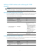
Splitting a 40-GE interface and combining split 10-GE interfaces IMPORTANT: For an HP FF 5930-32QSFP+ Switch (JG726A)/HP FF 5930-32QSFP+ TAA Switch (JG727A), only 40-GE interfaces FortyGigE 1/0/5 through FortyGigE 1/0/28 can be split into 10-GE interfaces. Splitting a 40-GE QSFP+ interface into four 10-GE interfaces You can use a 40-GE QSFP+ interface as a single interface.
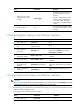
Step 3. 4. Command Remarks By default, a 40-GE interface is not split and operates as a single interface. Combine the four 10-GE interfaces into a 40-GE interface. using fortygige Reboot the device. N/A After you combine the four 10-GE interfaces, replace the dedicated 1-to-4 cable with a dedicated 1-to-1 cable or a 40-GE transceiver module. After creating the 40-GE interface, the system removes the four 10-GE interfaces.
Step Command Remarks 2. Enter Ethernet interface view. interface interface-type interface-number N/A 3. Change the link mode of the Ethernet interface. port link-mode { bridge | route } By default, Ethernet interfaces operate in route mode. Configuring jumbo frame support An Ethernet interface might receive some frames larger than the standard Ethernet frame size (called "jumbo frames") during high-throughput data exchanges, such as file transfers.
Forcibly bringing up a fiber port CAUTION: The following operations on a fiber port will cause link updown events before the port finally stays up: • Configure the port up-mode command and the speed or duplex command at the same time. • Install or remove fiber links or transceiver modules after you forcibly bring up the fiber port. As shown in Figure 1, a fiber port typically uses separate fibers for transmitting and receiving packets.
Step 2. Enter Ethernet interface view. 3. Forcibly bring up the fiber GE, 10-GE, or 40-GE port. Command Remarks interface interface-type interface-number N/A port up-mode By default, a fiber Ethernet port is not forcibly brought up, and the physical state of a fiber port depends on the physical state of the fibers. Displaying and maintaining an Ethernet interface Execute display commands in any view and reset commands in user view. Task Command Display interface traffic statistics.
Configuring loopback, null, and inloopback interfaces This chapter describes how to configure a loopback interface, a null interface, and an inloopback interface. Configuring a loopback interface A loopback interface is a virtual interface. The physical layer state of a loopback interface is always up unless the loopback interface is manually shut down.
Configuring a null interface A null interface is a virtual interface and is always up, but you can neither use it to forward data packets nor can you configure it with an IP address or link layer protocol. The null interface provides a simpler way to filter packets than ACL. You can filter undesired traffic by transmitting it to a null interface instead of applying an ACL.
Task Command Clear the statistics on the inloopback interface.
Bulk configuring interfaces You can enter interface range view to bulk configure multiple interfaces with the same feature instead of configuring them one by one. For example, you can execute the shutdown command in interface range view to shut down a range of interfaces. Failure to apply a command on one member interface does not affect the application of the command on the other member interfaces.
Step Command Remarks • interface range { interface-type 2. 3. 4. 5. interface-number [ to interface-type interface-number ] } &<1-5> Use either command. By using the interface range name command, you assign a name to an interface range and can specify this name rather than the interface range to enter the interface range view. Enter interface range view. • interface range name name (Optional.) Display commands available for the first interface in the interface range.
Configuring the MAC address table Overview An Ethernet device uses a MAC address table to forward frames. A MAC address entry contains a destination MAC address, an outgoing interface, and a VLAN ID. Upon receiving a frame, the device uses the destination MAC address of the frame to look for a match in the MAC address table. If a match is found, the device forwards the frame out of the outgoing interface in the matching entry.
• Static entries—Static entries are manually added in order to forward frames with a specific destination MAC address out of their associated interfaces and never age out. A static entry has higher priority than a dynamically learned one. • Dynamic entries—Dynamic entries can be manually configured or dynamically learned in order to forward frames with a specific destination MAC address out of their associated interfaces and might age out.
Step 2. Command Add or modify a static or dynamic MAC address entry. Remarks mac-address { dynamic | static } mac-address interface interface-type interface-number vlan vlan-id By default, no MAC address entry is configured globally. Make sure you have created the VLAN and assigned the interface to the VLAN. To adding or modifying a static or dynamic MAC address entry on an interface: Step 1. Enter system view. Command Remarks system-view N/A • Enter Layer 2 Ethernet interface 2.
You can reduce floods on a stable network by setting a long aging timer or disabling the aging timer to prevent dynamic entries from unnecessarily aging out. By reducing floods, you improve not only network performance, but also security, because the chances for a data frame to reach unintended destinations are reduced. To configure the aging timer for dynamic MAC address entries: Step 1. Enter system view. 2. Configure the aging timer for dynamic MAC address entries.
• The logging facility name and the severity level specified in the /etc/syslog.conf file must be identical to those configured on the device by using the info-center loghost and info-center source commands. Otherwise, the log information might not be output correctly to the log host. Configuration procedure # Add a static MAC address entry for MAC address 000f-e235-dc71 on FortyGigE 1/0/1 that belongs to VLAN 1.
Configuring MAC Information The MAC Information feature can generate syslog messages or SNMP notifications when MAC address entries are learned or deleted. You can use these messages to monitor users leaving or joining the network and analyze network traffic. The MAC Information feature buffers the MAC change syslog messages or SNMP notifications in a queue.
Step Command Remarks 1. Enter system view. system-view N/A 2. Configure the MAC Information mode. mac-address information mode { syslog | trap } Optional. The default setting is trap. Configuring the MAC change sending interval To prevent syslog messages or SNMP notifications from being sent too frequently, you can set the MAC change sending interval. To set the MAC change sending interval: Step Command Remarks 1. Enter system view. system-view N/A 2. Set the MAC change sending interval.
Figure 2 Network diagram Configuration procedure 1. Configure Device to send syslog messages to Host B: # Enable the information center. system-view [Device] info-center enable # Specify the log host 192.168.1.2/24 and specify local4 as the logging facility. [Device] info-center loghost 192.168.1.2 facility local4 # Disable log output to the log host.
147 # kill -HUP 147 # syslogd -r & Now, the device can output MAC address logs to the log host, which stores the logs to the specified file. 3. Enable MAC Information on Device: # Enable MAC Information globally. [Device] mac-address information enable # Configure the MAC Information mode as syslog.
Configuring Ethernet link aggregation Ethernet link aggregation bundles multiple physical Ethernet links into one logical link, called an aggregate link. Link aggregation has the following benefits: • Increased bandwidth beyond the limits of any single link. In an aggregate link, traffic is distributed across the member ports. • Improved link reliability. The member ports dynamically back up one another. When a member port fails, its traffic is automatically switched to other member ports.
Aggregation states of member ports in an aggregation group A member port in an aggregation group can be in either of the following aggregation states: • Selected—A Selected port can forward traffic. • Unselected—An Unselected port cannot forward traffic. Operational key When aggregating ports, the system automatically assigns each port an operational key based on port information, such as port rate and duplex mode. Any change to this information triggers a recalculation of the operational key.
• Static aggregation mode—Aggregation is stable. The aggregation state of the member ports are not affected by the peer ports. • Dynamic aggregation mode—The peering system automatically maintains the aggregation state of the member ports, thus reducing the workload of administrators. An aggregation group in static mode is called a "static aggregation group" and an aggregation group in dynamic mode is called a "dynamic aggregation group.
Figure 4 Setting the aggregation state of a member port in a static aggregation group The maximum number of Selected ports in a static aggregation group is 16. To ensure stable aggregation state and service continuity, do not change port attributes or class-two configurations on any member port. If you need to make this change, make sure you understand its impact on the live network.
LACP functions LACP offers basic LACP functions and extended LACP functions, as described in Table 2. Table 2 Basic and extended LACP functions Category Description Basic LACP functions Implemented through the basic LACPDU fields, including the system LACP priority, system MAC address, port priority, port number, and operational key. Extended LACP functions Implemented by extending the LACPDU with new TLV fields. The switch series can participate in LACP MAD only as an intermediate device.
Choosing a reference port The system chooses a reference port from the member ports that are in up state and have the same attribute configurations as the aggregate interface. A Selected port must have the same operational key and attribute configurations as the reference port. The local system (the actor) and the remote system (the partner) negotiate a reference port by using the following workflow: 1. Compare the system IDs. (A system ID comprises the system LACP priority and the system MAC address.
Figure 5 Setting the state of a member port in a dynamic aggregation group Meanwhile, the system with the higher system ID, being aware of the aggregation state changes on the remote system, sets the aggregation state of local member ports the same as their peer ports. When you aggregate interfaces in dynamic mode, follow these guidelines: • The maximum number of Selected ports in a dynamic aggregation group is 16.
A port that joins a dynamic aggregation group after the Selected port limit has been reached is placed in Selected state if it is more eligible to be selected than a current member port. • Load sharing criteria for link aggregation groups In a link aggregation group, traffic may be load-shared across the selected member ports based on a set of criteria, depending on your configuration.
• You must configure the same aggregation mode on the two ends of an aggregate link. • This switch series supports up to 128 aggregation groups. To ensure the operation of the service loopback groups, HP recommends configuring no more than 126 aggregation groups. Configuring a static aggregation group To guarantee a successful static aggregation, make sure that the ports at both ends of each link are in the same aggregation state.
Step 4. Command a. Enter Layer 3 Ethernet interface view: interface interface-type interface-number Assign an interface to the specified Layer 3 aggregation group. b. Assign the interface to the specified Layer 3 aggregation group: port link-aggregation group number Remarks Repeat these two sub-steps to assign more Layer 3 Ethernet interfaces to the aggregation group.
Step 9. Configure the short LACP timeout interval (3 seconds) on the interface. Command Remarks lacp period short By default, the long LACP timeout interval (90 seconds) is adopted by the interface. The peer sends LACPDUs slowly. Configuring a Layer 3 dynamic aggregation group Step 1. Enter system view. Command Remarks system-view N/A By default, the system LACP priority is 32768. Changing the system LACP priority might affect the aggregation state of the ports in the dynamic aggregation group.
Configuring an aggregate interface In addition to the configurations in this section, most of the configurations that can be performed on Layer 2 or Layer 3 Ethernet interfaces can also be performed on Layer 2 or Layer 3 aggregate interfaces. Configuring the description of an aggregate interface You can configure the description of an aggregate interface for administration purposes such as describing the purpose of the interface. To configure the description of an aggregate interface: Step 1.
Configuring the MTU of a Layer 3 aggregate interface Maximum transmission unit (MTU) of an interface affects IP packets fragmentation and reassembly on the interface. To change the MTU of a Layer 3 aggregate interface: Step Command Remarks 1. Enter system view. system-view N/A 2. Enter Layer 3 aggregate interface view. interface route-aggregation interface-number N/A 3. Configure the MTU of the Layer 3 aggregate interface. mtu size The default setting is 1500 bytes.
Configuring the expected bandwidth of an aggregate interface Step Enter system view. 1. Command Remarks system-view N/A • Enter Layer 2 aggregate Enter aggregate interface view. 2. interface view: interface bridge-aggregation interface-number • Enter Layer 3 aggregate N/A interface view: interface route-aggregation interface-number Configure the expected bandwidth of the interface. 3.
Step Command • Enter Layer 2 aggregate interface view: 2. Enter aggregate interface view. interface bridge-aggregation interface-number • Enter Layer 3 aggregate interface view: interface route-aggregation interface-number 3. Restore the default settings for the aggregate interface. default Configuring load sharing for link aggregation groups This section explains how to configure load sharing criteria for link aggregation groups and how to enable local-first load sharing for link aggregation.
Enabling link-aggregation traffic redirection Link-aggregation traffic redirection prevents traffic interruption. With this feature, when you shut down a Selected port in an aggregation group, traffic can be redirected to other Selected ports.
Task Command Display summary information about all aggregation groups. display link-aggregation summary Display detailed information about specific or all aggregation groups. display link-aggregation verbose [ { bridge-aggregation | route-aggregation } [ interface-number ] ] Clear LACP statistics for specific or all link aggregation member ports. reset lacp statistics [ interface interface-list ] Clear statistics for specific or all aggregate interfaces.
# Create Layer 2 aggregate interface Bridge-Aggregation 1. [DeviceA] interface bridge-aggregation 1 [DeviceA-Bridge-Aggregation1] quit # Assign ports FortyGigE 1/0/1 through FortyGigE 1/0/3 to link aggregation group 1.
Figure 7 Network diagram Configuration procedure 1. Configure Device A: # Create VLAN 10, and assign the port FortyGigE 1/0/4 to VLAN 10. system-view [DeviceA] vlan 10 [DeviceA-vlan10] port fortygige 1/0/4 [DeviceA-vlan10] quit # Create VLAN 20, and assign the port FortyGigE 1/0/5 to VLAN 20. [DeviceA] vlan 20 [DeviceA-vlan20] port fortygige 1/0/5 [DeviceA-vlan20] quit # Create Layer 2 aggregate interface Bridge-Aggregation 1, and configure the link aggregation mode as dynamic.
2. Configure Device B in the same way Device A is configured. (Details not shown.) Verifying the configuration # Display detailed information about all aggregation groups on Device A.
Figure 8 Network diagram Configuration procedure 1. Configure Device A: # Create VLAN 10, and assign the port FortyGigE 1/0/5 to VLAN 10. system-view [DeviceA] vlan 10 [DeviceA-vlan10] port fortygige 1/0/5 [DeviceA-vlan10] quit # Create VLAN 20, and assign the port FortyGigE 1/0/6 to VLAN 20.
[DeviceA-Bridge-Aggregation2] link-aggregation load-sharing mode destination-mac [DeviceA-Bridge-Aggregation2] quit # Assign ports FortyGigE 1/0/3 and FortyGigE 1/0/4 to link aggregation group 2.
source-mac address Bridge-Aggregation2 Load-Sharing Mode: destination-mac address The output shows that the load sharing criterion for link aggregation group 1 is the source MAC addresses of packets and that for link aggregation group 2 is the destination MAC addresses of packets.
G -- Defaulted, H -- Expired Aggregate Interface: Route-Aggregation1 Aggregation Mode: Static Loadsharing Type: Shar Port Status Priority Oper-Key -------------------------------------------------------------------------------FGE1/0/1 S 32768 1 FGE1/0/2 S 32768 1 FGE1/0/3 S 32768 1 The output shows that link aggregation group 1 is a non-load-shared Layer 3 static aggregation group that contains three Selected ports.
Verifying the configuration # Display detailed information about all aggregation groups on Device A.
Configuring spanning tree protocols Spanning tree protocols eliminate loops in a physical link-redundant network by selectively blocking redundant links and putting them in a standby state. The recent versions of STP include the Rapid Spanning Tree Protocol (RSTP) and the Multiple Spanning Tree Protocol (MSTP). STP STP was developed based on the 802.1d standard of IEEE to eliminate loops at the data link layer in a LAN.
Basic concepts in STP Root bridge A tree network must have a root bridge. The entire network contains only one root bridge, and all the other bridges in the network are called "leaf nodes". The root bridge is not permanent, but can change with changes of the network topology. Upon initialization of a network, each device generates and periodically sends configuration BPDUs, with itself as the root bridge. After network convergence, only the root bridge generates and periodically sends configuration BPDUs.
Calculation process of the STP algorithm The spanning tree calculation process described in the following sections is a simplified process for example only. Calculation process The STP algorithm uses the following calculation process: 1. Initialize the network. Upon initialization of a device, each port generates a BPDU with the port as the designated port, the device as the root bridge, 0 as the root path cost, and the device ID as the designated bridge ID. 2. Select the root bridge.
Step Actions 2 The device compares the configuration BPDUs of all the ports and chooses the optimum configuration BPDU. The following are the principles of configuration BPDU comparison: a. The configuration BPDU with the lowest root bridge ID has the highest priority. b. If configuration BPDUs have the same root bridge ID, their root path costs are compared. For example, the root path cost in a configuration BPDU plus the path cost of a receiving port is S.
Device Device B Device C 2. Port name Configuration BPDU on the port Port B1 {1, 0, 1, Port B1} Port B2 {1, 0, 1, Port B2} Port C1 {2, 0, 2, Port C1} Port C2 {2, 0, 2, Port C2} Compare the configuration BPDUs on each device. In Table 6, each configuration BPDU contains the following fields: root bridge ID, root path cost, designated bridge ID, and designated port ID.
Device Configuration BPDU on ports after comparison Comparison process • Port C1 receives the configuration BPDU of Port A2 {0, 0, 0, Port A2}, finds that the received configuration BPDU is superior to its existing configuration BPDU {2, 0, 2, Port C1}, and updates its configuration BPDU.
Figure 13 The final calculated spanning tree The configuration BPDU forwarding mechanism of STP The configuration BPDUs of STP are forwarded according to these guidelines: • Upon network initiation, every device regards itself as the root bridge, generates configuration BPDUs with itself as the root, and sends the configuration BPDUs at a regular hello interval.
The device uses the max age to determine whether a stored configuration BPDU has expired and discards it if the max age is exceeded. RSTP RSTP achieves rapid network convergence by allowing a newly elected root port or designated port to enter the forwarding state much faster than STP. If the old root port on the device has stopped forwarding data and the upstream designated port has started forwarding data, a newly elected RSTP root port rapidly enters the forwarding state.
Figure 14 Basic concepts in MSTP VLAN 1 MSTI 1 MSTI 2 VLAN 2 MSTI 0 Other VLANs VLAN 1 MSTI 1 MSTI 2 VLAN 2 MSTI 0 Other VLANs MST region 1 MST region 4 MST region 2 MST region 3 VLAN 1 MSTI 1 MSTI 2 VLAN 2 MSTI 0 Other VLANs CST VLAN 1 MSTI 1 MSTI 2 VLAN 2&3 MSTI 0 Other VLANs To MST region 2 Figure 15 Network diagram and topology of MST region 3 MST region A multiple spanning tree region (MST region) consists of multiple devices in a switched network and the network segments among them.
• Same VLAN-to-instance mapping configuration • Same MSTP revision level • Physically linked together Multiple MST regions can exist in a switched network. You can assign multiple devices to the same MST region. In Figure 14, the switched network comprises four MST regions, MST region 1 through MST region 4, and all devices in each MST region have the same MST region configuration.
Port roles A port can play different roles in different MSTIs. As shown in Figure 16, an MST region comprises Device A, Device B, Device C, and Device D. Port A1 and port A2 of Device A connect to the common root bridge. Port B2 and Port B3 of Device B form a loop. Port C3 and Port C4 of Device C connect to other MST regions. Port D3 of Device D directly connects to a host.
• Forwarding—The port receives and sends BPDUs, learns MAC addresses, and forwards user traffic. • Learning—The port receives and sends BPDUs, learns MAC addresses, but does not forward user traffic. Learning is an intermediate port state. • Discarding—The port receives and sends BPDUs, but does not learn MAC addresses or forward user traffic. NOTE: When in different MSTIs, a port can be in different states. A port state is not exclusively associated with a port role.
MSTP implementation on devices MSTP is compatible with STP and RSTP. Devices that are running MSTP and that are used for spanning tree calculation can identify STP and RSTP protocol packets.
STP configuration task list Tasks at a glance Configuring the root bridge: • • • • • • • • • (Required.) Setting the spanning tree mode (Optional.) Configuring the root bridge or a secondary root bridge (Optional.) Configuring the device priority (Optional.) Configuring the network diameter of a switched network (Optional.) Configuring spanning tree timers (Optional.) Configuring the timeout factor (Optional.) Configuring the BPDU transmission rate (Optional.
RSTP configuration task list Tasks at a glance Configuring the root bridge: • • • • • • • • • • • (Required.) Setting the spanning tree mode (Optional.) Configuring the root bridge or a secondary root bridge (Optional.) Configuring the device priority (Optional.) Configuring the network diameter of a switched network (Optional.) Configuring spanning tree timers (Optional.) Configuring the timeout factor (Optional.) Configuring the BPDU transmission rate (Optional.) Configuring edge ports (Optional.
MSTP configuration task list Tasks at a glance Configuring the root bridge: • • • • • • • • • • • • • • (Required.) Setting the spanning tree mode (Required.) Configuring an MST region (Optional.) Configuring the root bridge or a secondary root bridge (Optional.) Configuring the device priority (Optional.) Configuring the maximum hops of an MST region (Optional.) Configuring the network diameter of a switched network (Optional.) Configuring spanning tree timers (Optional.
• RSTP mode—All ports of the device send RSTP BPDUs. A port in this mode automatically transits to the STP mode when it receives STP BPDUs from the peer device, and a port in this mode does not transit to the MSTP mode when it receives MSTP BPDUs from the peer device. • MSTP mode—All ports of the device send MSTP BPDUs.
Step 6. 7. Command Remarks (Optional.) Display the MST region configurations that are not activated yet. check region-configuration N/A Manually activate MST region configuration. active region-configuration N/A Configuring the root bridge or a secondary root bridge You can have the spanning tree protocol determine the root bridge of a spanning tree through MSTP calculation, or you can specify the current device as the root bridge or as a secondary root bridge.
Configuring the current device as a secondary root bridge of a specific spanning tree Step 1. Enter system view. 2. Configure the current device as a secondary root bridge. Command Remarks system-view N/A • In STP/RSTP mode: stp root secondary • In MSTP mode: stp [ instance instance-list ] root secondary By default, a device does not function as a secondary root bridge. Configuring the device priority Device priority is a factor in calculating the spanning tree.
You can configure the maximum hops of an MST region based on the STP network size. HP recommends that you configure the maximum hops to a value that is greater than the maximum hops of each edge device to the root bridge. To configure the maximum number of hops of an MST region: Step Command Remarks 1. Enter system view. system-view N/A 2. Configure the maximum hops of the MST region. stp max-hops hops The default setting is 20.
To ensure a fast topology convergence, make sure the timer settings meet the following formulas: • 2 × (forward delay – 1 second) ≥ max age • Max age ≥ 2 × (hello time + 1 second) HP recommends not manually setting the spanning tree timers. HP recommends specifying the network diameter and letting spanning tree protocols automatically calculate the timers based on the network diameter. If the network diameter uses the default value, the timers also use their default values.
After the network topology is stabilized, each non-root-bridge device forwards configuration BPDUs to the downstream devices at the hello interval to detect link failures. If a device does not receive a BPDU from the upstream device within nine times the hello time, it assumes that the upstream device has failed and starts a new spanning tree calculation process. Sometimes a device might fail to receive a BPDU from the upstream device because the upstream device is busy.
Configuration restrictions and guidelines • If BPDU guard is disabled, a port set as an edge port becomes a non-edge port again if it receives a BPDU from another port. To restore the edge port, re-enable it. • If a port directly connects to a user terminal, configure it as an edge port and enable BPDU guard for it. This enables the port to quickly transit to the forwarding state when ensuring network security. • On a port, the loop guard function and the edge port setting are mutually exclusive.
formula of IEEE 802.1t is: Path cost = 200,000,000/link speed (in 100 kbps), where link speed is the sum of the link speed values of the Selected ports in the aggregation group. IEEE 802.1d-1998 or the private standard always assigns the smallest possible value to a single port or an aggregate interface when the link speed of the port or interface exceeds 10 Gbps. The forwarding path selected based on this criterion might not be the best one.
Path cost Link speed 1000 Mbps 10 Gbps 20 Gbps 40 Gbps Port type IEEE 802.1d-1998 IEEE 802.
Path cost Link speed Port type IEEE 802.1d-1998 IEEE 802.1t Private standard Aggregate interface containing two Selected ports 100 1 Aggregate interface containing three Selected ports 66 1 Aggregate interface containing four Selected ports 50 1 Configuring path costs of ports When the path cost of a port changes, the system re-calculates the role of the port and initiates a state transition. To configure the path cost of a port: Step Command Remarks 1. Enter system view.
On a spanning tree device, a port can have different priorities and play different roles in different spanning trees, so that data of different VLANs can be propagated along different physical paths, implementing per-VLAN load balancing. You can set port priority values based on the actual networking requirements. When the priority of a port changes, the system re-calculates the port role and initiates a state transition. To configure the priority of a port: Step Command Remarks 1. Enter system view.
Configuring the mode a port uses to recognize and send MSTP packets A port can receive and send MSTP packets in the following formats: • dot1s—802.1s-compliant standard format • legacy—Compatible format By default, the packet format recognition mode of a port is auto. The port automatically distinguishes the two MSTP packet formats, and determines the format of packets that it will send based on the recognized format. You can configure the MSTP packet format on a port.
Enabling the spanning tree feature You must enable the spanning tree feature for the device before any other spanning tree related configurations can take effect. Make sure the spanning tree feature is enabled globally and on the desired ports. You can disable the spanning tree feature for certain ports with the undo stp enable command to exclude them from spanning tree calculation and save CPU resources of the device. To enable the spanning tree feature: Step 1. Enter system view.
Configuration restrictions and guidelines The mCheck operation takes effect on devices operating in MSTP or RSTP mode. Configuration procedure Performing mCheck globally Step Command 1. Enter system view. system-view 2. Perform mCheck. stp global mcheck Performing mCheck in interface view Step Command 1. Enter system view. system-view 2. Enter Layer 2 Ethernet or aggregate interface view. interface interface-type interface-number 3. Perform mCheck.
caution. If the local device has different VLAN-to-instance mappings than its neighboring devices, loops or traffic interruption occurs. • To make Digest Snooping take effect, you must enable Digest Snooping both globally and on associated ports. HP recommends that you enable Digest Snooping on all associated ports first and then enable it globally. This will make the configuration take effect on all configured ports and reduce impact on the network.
Figure 17 Network diagram MST region Device C (Root bridge) FGE1/0/1 Root port FGE1/0/2 Designated port Blocked port Normal link FGE1/0/1 FGE1/0/1 FGE1/0/2 Blocked link FGE1/0/2 Device A Device B Configuration procedure # Enable Digest Snooping on FortyGigE 1/0/1 of Device A and enable global Digest Snooping on Device A.
Figure 18 Rapid state transition of an MSTP designated port Figure 19 Rapid state transition of an RSTP designated port If the upstream device is a third-party device, the rapid state transition implementation might be limited.
To configure No Agreement Check: Step Command Remarks 1. Enter system view. system-view N/A 2. Enter Layer 2 Ethernet or aggregate interface view. interface interface-type interface-number N/A 3. Enable No Agreement Check. stp no-agreement-check By default, No Agreement Check is disabled. No Agreement Check configuration example Network requirements As shown in Figure 20: • Device A connects to a third-party device that has a different spanning tree implementation.
Enabling BPDU guard For access layer devices, the access ports can directly connect to the user terminals (such as PCs) or file servers. The access ports are configured as edge ports to allow rapid transition. When these ports receive configuration BPDUs, the system automatically sets the ports as non-edge ports and starts a new spanning tree calculation process. This causes a change of network topology. Under normal conditions, these ports should not receive configuration BPDUs.
Step Command Remarks 2. Enter Layer 2 Ethernet or aggregate interface view. interface interface-type interface-number N/A 3. Enable the root guard function. stp root-protection By default, root guard is disabled. Enabling loop guard By continuing to receive BPDUs from the upstream device, a device can maintain the state of the root port and blocked ports. However, link congestion or unidirectional link failures might cause these ports to fail to receive BPDUs from the upstream devices.
Step Command Remarks 1. Enter system view. system-view N/A 2. Enter Layer 2 Ethernet or aggregate interface view. interface interface-type interface-number N/A 3. Enable port role restriction. stp role-restriction By default, port role restriction is disabled. Configuring TC-BPDU transmission restriction CAUTION: Enabling TC-BPDU transmission restriction on a port might cause the previous forwarding address table to fail to be updated when the topology changes.
Step Command Remarks 2. Enable the TC-BPDU guard function. stp tc-protection 3. (Optional.) Configure the maximum number of forwarding address entry flushes that the device can perform every 10 seconds. stp tc-protection threshold number By default, TC-BPDU guard is enabled. HP recommends not disabling this feature. The default setting is 6.
Task Command Display the spanning tree status and statistics. display stp [ instance instance-list ] [ interface interface-list | slot slot-number ] [ brief ] Display the MST region configuration information that has taken effect. display stp region-configuration Display the root bridge information of all MSTIs. display stp root Clear the spanning tree statistics.
{ 2. Configure the ports on these devices as trunk ports and assign them to related VLANs. Configure Device A: # Enter MST region view, configure the MST region name as example, map VLAN 10, VLAN 30, and VLAN 40 to MSTI 1, MSTI 3, and MSTI 4, respectively, and configure the revision level of the MST region as 0.
[DeviceC-mst-region] instance 4 vlan 40 [DeviceC-mst-region] revision-level 0 # Activate MST region configuration. [DeviceC-mst-region] active region-configuration [DeviceC-mst-region] quit # Specify the current device as the root bridge of MSTI 4. [DeviceC] stp instance 4 root primary # Enable the spanning tree feature globally. [DeviceC] stp global enable 5.
0 FortyGigE1/0/1 DESI FORWARDING NONE 0 FortyGigE1/0/2 DESI FORWARDING NONE 0 FortyGigE1/0/3 DESI FORWARDING NONE 1 FortyGigE1/0/2 DESI FORWARDING NONE 1 FortyGigE1/0/3 ROOT FORWARDING NONE 3 FortyGigE1/0/1 DESI FORWARDING NONE 3 FortyGigE1/0/3 DESI FORWARDING NONE # Display brief spanning tree information on Device C.
Configuring loop detection Overview Incorrect network connections or configurations can create Layer 2 loops, which results in repeated transmission of broadcasts, multicasts, or unknown unicasts, waste network resources, and sometimes even paralyze networks. The loop detection mechanism immediately generates a log when a loop occurs so that you are promptly notified to adjust network connections and configurations. You can even configure loop detection to shut down the looped port.
• Version—Protocol version, which is always 0x0000. • Length—Length of the frame. The value includes the inner header, but excludes the Ethernet header. • Reserved—This field is reserved. Frames for loop detection are encapsulated as TLV triplets. Table 9 TLVs supported by loop detection TLV Description Remarks End of PDU End of a PDU. Optional. Device ID Bridge MAC address of the sending device. Required. Port ID ID of the PDU sending port. Optional.
When the loop protection action shutdown is used, the switch automatically shuts down a port upon detecting a loop on the port. After the detection timer set by using the shutdown-interval command expires, the switch automatically brings up the port. The process is repeated until the loop is removed. NOTE: Incorrect recovery can occur when loop detection frames are discarded to reduce the load. To avoid this problem, use the shutdown action or manually remove the loop.
Configuring the loop protection action You can configure the loop protection action globally or on specific ports. The global configuration applies to all ports. The per-port configuration applies to the individual ports. The per-port configuration takes precedence over the global configuration. Configuring the global loop protection action Step Command Remarks 1. Enter system view. system-view N/A 2. Configure the global loop protection action.
Setting the loop detection interval With loop detection enabled, the switch sends loop detection frames at a specified interval. A shorter interval offers more sensitive detection but consumes more resources. Consider the system performance and loop detection speed when you set the loop detection interval. To set the loop detection interval: Step Command Remarks 1. Enter system view. system-view N/A 2. Set the loop detection interval.
Configuration procedure 1. Configure Device A: # Create VLAN 100, and globally enable loop detection for the VLAN. system-view [DeviceA] vlan 100 [DeviceA-vlan100] quit [DeviceA] loopback-detection global enable vlan 100 # Configure FortyGigE 1/0/1 and FortyGigE 1/0/2 as trunk ports, and assign them to VLAN 100.
[DeviceC-FortyGigE1/0/1] port trunk permit vlan 100 [DeviceC-FortyGigE1/0/1] quit [DeviceC] interface fortygige 1/0/2 [DeviceC-FortyGigE1/0/2] port link-type trunk [DeviceC-FortyGigE1/0/2] port trunk permit vlan 100 [DeviceC-FortyGigE1/0/2] quit Verifying the configuration After the configurations are complete, Device A detects loops on ports FortyGigE 1/0/1 and FortyGigE 1/0/2 within a loop detection interval.
Configuring VLANs This chapter provides an overview of VLANs and explains how to configure them. Overview Ethernet is a family of shared-media LAN technologies based on the CSMA/CD mechanism. An Ethernet LAN is both a collision domain and a broadcast domain. As the medium is shared, collisions and broadcasts are common in an Ethernet LAN.
Figure 27 VLAN tag placement and format A VLAN tag includes the following fields: • TPID—16-bit tag protocol identifier that indicates whether a frame is VLAN-tagged. By default, the TPID value is 0x8100, indicating that the frame is VLAN-tagged. • Priority—3-bit long 802.1p priority of the frame. For more information, see ACL and QoS Configuration Guide.
Step 5. Configure the description of the VLAN. Command Remarks description text The default setting is VLAN vlan-id, which is the ID of the VLAN. For example, the description of VLAN 100 is VLAN 0100 by default. NOTE: • As the default VLAN, VLAN 1 cannot be created or removed. • You cannot use the undo vlan command to delete a dynamic VLAN, a VLAN with a QoS policy applied, or a VLAN locked by an application. To delete such a VLAN, first remove the configuration from the VLAN.
Configuring port-based VLANs Introduction to port-based VLAN Port-based VLANs group VLAN members by port. A port forwards packets from a VLAN only after it is assigned to the VLAN. Port link type You can configure the link type of a port as access, trunk, or hybrid. The link types use the following VLAN tag handling methods: • Access—An access port can forward packets from only one specific VLAN and send these packets untagged.
Actions Access Trunk Hybrid • Removes the tag and sends In the outbound direction Sends the frame if its VLAN is permitted on the port. The frame is sent with the VLAN tag removed or intact depending on your configuration with the port hybrid vlan command. This is true of the PVID. the frame if the frame carries the PVID tag and the port belongs to the PVID. Removes the VLAN tag and sends the frame.
Assigning a trunk port to a VLAN A trunk port can carry multiple VLANs. You can assign it to a VLAN in interface view. When you assign a trunk port to a VLAN, follow these guidelines: • To change the link type of a port from trunk to hybrid or vice versa, set the link type to access first. • You must configure the trunk port to allow packets from the PVID to pass through by using the port trunk permit vlan command. To assign a trunk port to one or multiple VLANs: Step 1. Enter system view.
Step 1. Enter system view. Command Remarks system-view N/A • The configuration made in Layer 2 Ethernet interface view applies only to the port. • The configuration made in • Enter Layer 2 Ethernet interface 2. Enter interface view. view: interface interface-type interface-number • Enter Layer 2 aggregate interface view: interface bridge-aggregation interface-number Layer 2 aggregate interface view applies to the aggregate interface and its aggregation member ports.
To ensure communication security and avoid broadcast storms, VLANs are configured in the enterprise network to isolate Layer 2 packets of different departments. VLAN 100 is assigned to Department A, and VLAN 200 is assigned to Department B. Make sure hosts within the same VLAN can communicate with each other: Host A can communicate with Host C, and Host B can communicate with Host D. Figure 28 Network diagram Configuration procedure 1.
VLAN ID: 100 VLAN type: Static Route interface: Not configured Description: VLAN 0100 Name: VLAN 0100 Tagged ports: FortyGigE1/0/3 Untagged ports: FortyGigE1/0/1 [DeviceA-FortyGigE1/0/3] display vlan 200 VLAN ID: 200 VLAN type: Static Route interface: Not configured Description: VLAN 0200 Name: VLAN 0200 Tagged ports: FortyGigE1/0/3 Untagged ports: FortyGigE1/0/2 103
Configuring LLDP Overview In a heterogeneous network, a standard configuration exchange platform ensures that different types of network devices from different vendors can discover one another and exchange configuration for the sake of interoperability and management. The Link Layer Discovery Protocol (LLDP) is specified in IEEE 802.1AB. The protocol operates on the data link layer to exchange device information between directly connected devices.
LLDPDU formats LLDP sends device information in LLDPDUs. LLDPDUs are encapsulated in Ethernet II or SNAP frames. 1. LLDPDU encapsulated in Ethernet II Figure 30 Ethernet II-encapsulated LLDPDU Table 10 Fields in an Ethernet II-encapsulated LLDPDU Field Description Destination MAC address MAC address to which the LLDPDU is advertised.
Table 11 Fields in a SNAP-encapsulated LLDPDU Field Description Destination MAC address MAC address to which the LLDPDU is advertised. It is the same as that for Ethernet II-encapsulated LLDPDUs. Source MAC address MAC address of the sending port. Type SNAP type for the upper layer protocol. It is 0xAAAA-0300-0000-88CC for LLDP. Data LLDPDU. FCS Frame check sequence, a 32-bit CRC value used to determine the validity of the received Ethernet frame.
Type Description End of LLDPDU Marks the end of the TLV sequence in the LLDPDU. Port Description Specifies the port description of the sending port. System Name Specifies the assigned name of the sending device. System Description Specifies the description of the sending device. System Capabilities Identifies the primary functions of the sending device and the enabled primary functions.
NOTE: The Power Stateful Control TLV is defined in IEEE P802.3at D1.0 and is not supported in later versions. HP devices send this type of TLVs only after receiving them. 4. LLDP-MED TLVs LLDP-MED TLVs provide multiple advanced applications for voice over IP (VoIP), such as basic configuration, network policy configuration, and address and directory management. LLDP-MED TLVs provide a cost-effective and easy-to-use solution for deploying voice devices in Ethernet. LLDP-MED TLVs are shown in Table 15.
Work mechanism LLDP operating modes An LLDP agent can operate in one of the following modes: • TxRx mode—An LLDP agent in this mode can send and receive LLDPDUs. • Tx mode—An LLDP agent in this mode can only send LLDPDUs. • Rx mode—An LLDP agent in this mode can only receive LLDPDUs. • Disable mode—An LLDP agent in this mode cannot send or receive LLDPDUs. Each time the LLDP operating mode of an LLDP agent changes, its LLDP protocol state machine re-initializes.
LLDP configuration task list Tasks at a glance Performing basic LLDP configuration: • • • • • • • • • (Required.) Enabling LLDP (Optional.) Configuring the LLDP bridge mode (Optional.) Setting the LLDP operating mode (Optional.) Setting the LLDP re-initialization delay (Optional.) Enabling LLDP polling (Optional.) Configuring the advertisable TLVs (Optional.) Configuring the management address and its encoding format (Optional.) Setting other LLDP parameters (Optional.
Step 3. 4. Command Remarks Enter Layer 2/Layer 3 Ethernet interface view or Layer 2/Layer 3 aggregate interface view. interface interface-type interface-number N/A (Optional.) Enable LLDP. lldp enable By default, LLDP is enabled on a port. Configuring the LLDP bridge mode The following LLDP bridge modes are available: service bridge mode and customer bridge mode. • In service bridge mode, LLDP supports nearest bridge agents and nearest non-TPMR bridge agents.
Step Command Remarks • In Layer 2 or Layer 3 Ethernet interface 3. Set the LLDP operating mode. view: lldp [ agent { nearest-customer | nearest-nontpmr } ] admin-status { disable | rx | tx | txrx } • In Layer 2 or Layer 3 aggregate interface view: lldp agent { nearest-customer | nearest-nontpmr } admin-status { disable | rx | tx | txrx } By default, the nearest bridge agent operates in txrx mode, and the nearest customer bridge agent and nearest non-TPMR bridge agent operate in disable mode.
Step Command Remarks • In Layer 2 or Layer 3 Ethernet interface 3. Enable LLDP polling and set the polling interval. view: lldp [ agent { nearest-customer | nearest-nontpmr } ] check-change-interval interval • In Layer 2 or Layer 3 aggregate interface By default, LLDP polling is disabled. view: lldp agent { nearest-customer | nearest-nontpmr } check-change-interval interval Configuring the advertisable TLVs Step Command Remarks 1. Enter system view. system-view N/A 2.
Step 4. Configure the advertisable TLVs (in Layer 3 Ethernet interface view).
Configuring the management address and its encoding format LLDP encodes management addresses in numeric or string format in management address TLVs. By default, management addresses are encoded in numeric format. If a neighbor encodes its management address in character string format, you must configure the encoding format of the management address as string on the connecting port to guarantee normal communication with the neighbor.
TTL = Min (65535, (TTL multiplier × LLDPDU transmit interval + 1)) As the expression shows, the TTL can be up to 65535 seconds. TTLs greater than 65535 will be rounded down to 65535 seconds. To change LLDP parameters: Step Command Remarks 1. Enter system view. system-view N/A 2. Set the TTL multiplier. lldp hold-multiplier value The default setting is 4. 3. Set the LLDPDU transmit interval. lldp timer tx-interval interval The default setting is 30 seconds. 4.
Configuring CDP compatibility When the switch is directly connected to a Cisco device that supports only CDP rather than LLDP, you can enable CDP compatibility to enable the switch to exchange information with the directly-connected device. With CDP compatibility enabled on the switch, the switch can use LLDP to receive and recognize the CDP packets received from the directly-connected device and send CDP packets to the directly-connected device.
Configuring LLDP trapping and LLDP-MED trapping LLDP trapping or LLDP-MED trapping notifies the network management system of events such as newly detected neighboring devices and link malfunctions. To prevent excessive LLDP traps from being sent when the topology is unstable, set a trap transmit interval for LLDP. To configure LLDP trapping and LLDP-MED trapping: Step Command Remarks 1. Enter system view. system-view N/A 2.
Task Command Display LLDP status of a port. display lldp status [ interface interface-type interface-number ] [ agent { nearest-bridge | nearest-customer | nearest-nontpmr } ] Display types of advertisable optional LLDP TLVs. display lldp tlv-config [ interface interface-type interface-number ] [ agent { nearest-bridge | nearest-customer | nearest-nontpmr } ] Basic LLDP configuration example Network requirements As shown in Figure 33, the NMS and Switch A are located in the same Ethernet network.
# Enable LLDP on FortyGigE 1/0/1. (You can skip this step because LLDP is enabled on ports by default.) Set the LLDP operating mode to Tx. [SwitchB] interface fortygige 1/0/1 [SwitchB-FortyGigE1/0/1] lldp enable [SwitchB-FortyGigE1/0/1] lldp admin-status tx [SwitchB-FortyGigE1/0/1] quit 3. Verify the configuration: # Display the global LLDP status and port LLDP status on Switch A.
LLDP agent nearest-bridge: Port status of LLDP : Enable Admin status : RX_Only Trap flag : No MED trap flag : No Polling interval : 0s Number of LLDP neighbors : 1 Number of MED neighbors : 0 Number of CDP neighbors : 0 Number of sent optional TLV : 21 Number of received unknown TLV : 3 LLDP agent nearest-nontpmr: Port status of LLDP : Enable Admin status : Disable Trap flag : No MED trap flag : No Polling interval : 0s Number of LLDP neighbors : 0 Number of MED neighbors : 0
Fast transmit interval : 1s Transmit credit max : 5 Hold multiplier : 4 Reinit delay : 2s Trap interval : 30s Fast start times : 4 LLDP status information of port 1 [FortyGigE1/0/1]: LLDP agent nearest-bridge: Port status of LLDP : Enable Admin status : RX_Only Trap flag : No MED trap flag : No Polling interval : 0s Number of LLDP neighbors : 1 Number of MED neighbors : 1 Number of CDP neighbors : 0 Number of sent optional TLV : 0 Number of received unknown TLV : 5 LLDP agent
Trap flag : No MED trap flag : No Polling interval : 0s Number of LLDP neighbors : 0 Number of MED neighbors : 0 Number of CDP neighbors : 0 Number of sent optional TLV : 1 Number of received unknown TLV : 0 LLDP agent nearest-customer: Port status of LLDP : Enable Admin status : Disable Trap flag : No MED trap flag : No Polling interval : 0s Number of LLDP neighbors : 0 Number of MED neighbors : 0 Number of CDP neighbors : 0 Number of sent optional TLV : 16 Number of receive
Configuring service loopback groups A service loopback group contains one or multiple Ethernet ports for looping packets sent out by the device back to the device. This feature must work with other features, such as GRE. A service loopback group provides one of the following services: • Tunnel—Supports unicast tunnel traffic. • Multicast tunnel—Supports multicast tunnel traffic. The device supports only one service loopback group for each service type.
Displaying and maintaining service loopback groups Execute display commands in any view. Task Command Display information about the service loopback group. display service-loopback group [ number ] Service loopback group configuration example Network requirements All Ethernet ports on Device A support the tunnel service. Assign FortyGigE 1/0/1 through FortyGigE 1/0/3 to a service loopback group for looping GRE packets sent out by the device back to the device.
Configuring cut-through Layer 2 forwarding A cut-through forwarding-enabled device forwards a frame after it receives the first 64 bytes of the frame. This feature reduces the transmission time of a frame within the device, and enhances forwarding performance. To configure cut-through forwarding: Step Command Remarks 1. Enter system view. system-view N/A 2. Enable cut-through forwarding. cut-through enable By default, cut-through forwarding is disabled.
Support and other resources Contacting HP For worldwide technical support information, see the HP support website: http://www.hp.
Conventions This section describes the conventions used in this documentation set. Command conventions Convention Description Boldface Bold text represents commands and keywords that you enter literally as shown. Italic Italic text represents arguments that you replace with actual values. [] Square brackets enclose syntax choices (keywords or arguments) that are optional. { x | y | ... } Braces enclose a set of required syntax choices separated by vertical bars, from which you select one.
Network topology icons Represents a generic network device, such as a router, switch, or firewall. Represents a routing-capable device, such as a router or Layer 3 switch. Represents a generic switch, such as a Layer 2 or Layer 3 switch, or a router that supports Layer 2 forwarding and other Layer 2 features. Represents an access controller, a unified wired-WLAN module, or the switching engine on a unified wired-WLAN switch. Represents an access point.
Index Numerics bandwidth Ethernet link aggregate interface (expected bandwidth), 34 10-GE interface combine, 2, 2 40-GE interface split, 2 802.x 802.1 LLDPDU TLV types, 106 802.
MSTP CIST calculation, 57 Layer 2 Ethernet link aggregation load sharing, 40 STP algorithm, 48 Layer 2 Ethernet link dynamic aggregation, 38 STP port path cost calculation standard, 68 STP timeout factor, 66 Layer 2 Ethernet link dynamic aggregation group, 30 LLDP CDP compatibility, 117 Layer 2 Ethernet link static aggregation group, 29 Layer 2 Ethernet link static aggregation, 37 CDP Layer 3 aggregate interface (MTU), 33 changing Layer 3 Ethernet link dynamic aggregation, 44 MAC Information ch
null interface, 7, 8 designated RSTP, 46, 58, 84 MST port, 56 RSTP device priority, 64 STP bridge, 47 RSTP root bridge, 63 STP port, 47 RSTP root bridge device, 63 device RSTP secondary root bridge, 63 Ethernet interface configuration, 1 RSTP secondary root bridge device, 64 Layer 2 cut-through forwarding configuration, 126 service loopback group, 124, 124, 125 LLDP basic configuration, 110, 119 STP, 46, 58, 84 LLDP CDP compatibility, 117 STP BPDU transmission rate, 67 LLDP configuration,
null interface, 8 LLDPDU encapsulated in SNAP format, 105 RSTP, 83 LLDPDU encapsulation format, 116 service loopback group, 125 VLAN frame encapsulation, 95 STP, 83 Ethernet VLAN, 101 interface. See Ethernet interface dot1d-1998 (STP port path cost calculation), 68 link aggregation.
configuration types, 22 LLDP management address encoding format, 115 displaying, 36 LLDPDU encapsulated in Ethernet II, 105 dynamic group configuration, 30 LLDPDU encapsulated in SNAP format, 105 dynamic mode, 24 LLDPDU encapsulation format, 116 dynamic process, 25 forwarding group configuration, 28 Layer 2 cut-through forwarding configuration, 126 group load-sharing criteria, 35 MST forwarding port state, 56 ignored VLAN on Layer 2 aggregate interface, 32 STP BPDU forwarding, 52 interface c
setting Ethernet link aggregate group min/max number Selected ports, 33 Ethernet link aggregation, 24 LAN VLAN basic configuration, 96 H VLAN configuration, 95 hello VLAN port-based configuration, 98, 101 STP timer, 52, 65 hybrid port port-based VLAN assignment, 100 VLAN-interface basic configuration, 97 Layer 2 cut-through forwarding configuration, 126 I Ethernet aggregate interface (description), 32 ignored VLAN Ethernet aggregate interface configuration, 32 Layer 2 aggregate interface, 32 Et
LLDPDU encapsulation format, 116 Ethernet link dynamic aggregation configuration, 44 LLDPDU format, 105 Ethernet link dynamic aggregation group configuration, 30, 31 LLDPDU management address TLV, 108 LLDPDU reception, 109 Ethernet link static aggregation configuration, 43 LLDPDU TLV types, 106 Ethernet link static aggregation group configuration, 29, 29 LLDPDU transmission, 109 LLDPDU TLVs, 106 LLDP-MED trapping configuration, 118 LLDP basic configuration, 119 management address configuration, 1
Ethernet link aggregation per-packet load-sharing, 28 MAC Information change send interval, 18 Layer 2 Ethernet link aggregation configuration, 40 configuration, 17, 18 enable, 17 logging mode configuration, 17 loop detection configuration, 88, 90, 92 loop MSTP configuration, 46, 58, 84 RSTP configuration, 46, 58, 84 queue length configuration, 18 MAC relay (LLDP agent), 104 maintaining Ethernet interface, 6 STP configuration, 46, 58, 84 Ethernet link aggregation, 36 STP loop guard, 81 inloopback
Ethernet 10-GE interfaces into 40-GE interface combine, 2 modifying MAC address table blackhole entry, 14 Ethernet 40-GE interface split, 2 MST Ethernet interface basic settings configuration, 3 CIST, 55 common root bridge, 55 Ethernet interface common settings configuration, 1 CST, 55 Ethernet interface jumbo frame support configuration, 4 IST, 55 Ethernet interface link mode, 3 MSTI, 55 Ethernet interface statistics polling interval, 4 port roles, 56 Ethernet link aggregation configuration t
STP edge port, 67 MSTP configuration, 46, 58, 84 STP loop guard, 81 null interface configuration, 7 STP mode set, 61 RSTP configuration, 46, 58, 84 STP No Agreement Check, 77, 79 service loopback group configuration, 124 STP path cost, 47 STP configuration, 46, 58, 84 STP port link type, 72 VLAN basic configuration, 96 STP port mode, 73 VLAN configuration, 95 STP port path cost, 68, 71 No Agreement Check (STP), 77, 79 STP port priority, 71 no-learning action (loop detection), 89 STP port r
Ethernet link aggregate interface default settings, 34 Layer 3 Ethernet link static aggregation configuration, 43 Ethernet link aggregation configuration, 21, 28, 37 Layer 3 Ethernet static link aggregation group configuration, 29 Ethernet link aggregation configuration types, 22 LLDP basic configuration, 110, 119 LLDP configuration, 104, 110 Ethernet link aggregation dynamic mode, 24 LLDP disable operating mode, 109, 111 Ethernet link aggregation group configuration, 28 LLDP enable, 110 LLDP opera
STP path cost calculation standard, 68 configuring Ethernet link aggregation, 28, 37 STP path cost configuration, 68, 71 configuring Ethernet link aggregation global load-sharing criteria, 35 STP port link type configuration, 72 configuring Ethernet link aggregation group, 28 STP port mode configuration, 73 configuring Ethernet link aggregation group load-sharing criteria, 35 STP port priority configuration, 71 STP port role restriction, 81 configuring Ethernet link aggregation group-specific load-
configuring loop detection protection action (global), 91 configuring STP root bridge, 63 configuring loop detection protection action (Layer 2 aggregate interface), 91 configuring STP secondary root bridge, 63 configuring STP root bridge device, 63 configuring STP secondary root bridge device, 64 configuring loop detection protection action (Layer 2 Ethernet interface), 91 configuring STP switched network diameter, 65 configuring STP TC-BPDU transmission restriction, 82 configuring loopback interfac
maintaining Ethernet link aggregation, 36 Q maintaining inloopback interface, 8 queuing maintaining loopback interface, 8 maintaining MSTP, 83 maintaining null interface, 8 maintaining RSTP, 83 maintaining STP, 83 MAC Information queue length, 18 R rate STP BPDU transmission rate, 67 maintaining VLAN, 101 receiving modifying MAC address table blackhole entry, 14 recovering LLDPDUs, 109 loop detection port status auto recovery, 89 performing STP mCheck, 74 performing STP mCheck globally, 75 refer
STP secondary root bridge configuration, 63 LLDPDU encapsulated in SNAP format, 105 RSTP, 46, See also STP configuration, 46, 58, 60, 84 LLDPDU encapsulation format, 116 SNMP device priority configuration, 64 displaying, 83 MAC Information configuration, 17, 18 snooping maintaining, 83 STP Digest Snooping, 75, 76 mode set, 61 spanning tree.
Digest Snooping configuration restrictions, 75 switched network diameter, 65 displaying, 83 TC-BPDU guard, 82 edge port configuration, 67 TC-BPDU transmission restriction, 82 edge port configuration restrictions, 68 timeout factor configuration, 66 feature enable, 74 timer configuration, 65 IST, 55 timer configuration restrictions, 66 loop detection, 46 timers, 52 loop guard enable, 81 VLAN-to-instance mapping table, 55 maintaining, 83 switching mCheck, 74 Ethernet interface configuration
LLDP parameters, 115 LLDPDU basic management types, 106 PVID, 98 voice traffic LLDPDU LLDP-MED types, 106 LLDP CDP compatibility, 117 LLDPDU management address TLV, 108 LLDPDU organization-specific types, 106 topology STP TCN BPDU protocol packets, 46 traffic Ethernet link aggregation traffic redirection, 36 transmitting LLDPDUs, 109 STP TC-BPDU transmission restriction, 82 trapping LLDP configuration, 118 LLDP-MED configuration, 118 MAC Information configuration, 17, 18 MAC Information mode configurati