HP FlexFabric 5930 Switch Series Layer 3 - IP Services Configuration Guide Part number: 5998-4571 Software version: Release 2406 & Release 2407P01 Document version: 6W101-20140404
Legal and notice information © Copyright 2014 Hewlett-Packard Development Company, L.P. No part of this documentation may be reproduced or transmitted in any form or by any means without prior written consent of Hewlett-Packard Development Company, L.P. The information contained herein is subject to change without notice.
Contents Configuring ARP ··························································································································································· 1 Overview············································································································································································ 1 ARP message format ·······························································································································
Configuring an address pool on the DHCP server ····································································································· 24 Configuration task list ··········································································································································· 24 Creating a DHCP address pool ··························································································································· 25 Specifying IP address ranges for a DH
Symptom ································································································································································· 53 Analysis ·································································································································································· 53 Solution ···························································································································································
Dynamic domain name resolution configuration example ··············································································· 76 Troubleshooting IPv4 DNS configuration ···················································································································· 79 Symptom ································································································································································· 79 Solution ···································
Configuration procedure ···································································································································· 107 Verifying the configuration ································································································································· 108 Troubleshooting IPv6 basics configuration ················································································································ 111 Symptom ······················
Index ········································································································································································ 155 vi
Configuring ARP This chapter describes how to configure the Address Resolution Protocol (ARP). Overview ARP resolves IP addresses into MAC addresses on Ethernet networks. ARP message format ARP uses two types of messages: ARP request and ARP reply. Figure 1 shows the format of ARP request/reply messages. Numbers in the figure refer to field lengths. Figure 1 ARP message format • Hardware type—Hardware address type. The value 1 represents Ethernet.
2. If Host A finds no entry for Host B, Host A buffers the packet and broadcasts an ARP request. The payload of the ARP request comprises the following information: { Sender IP address and sender MAC address—Host A's IP address and MAC address. { Target IP address—Host B's IP address. { Target MAC address—An all-zero MAC address. All hosts on this subnet can receive the broadcast request, but only the requested host (Host B) processes the request. 3.
Static ARP entry A static ARP entry is manually configured and maintained. It does not age out and cannot be overwritten by any dynamic ARP entry. Static ARP entries protect communication between devices because attack packets cannot modify the IP-to-MAC mapping in a static ARP entry. Static ARP entries include long and short ARP entries. • A long static ARP entry comprises the IP address, MAC address, VLAN, and output interface. It is directly used for forwarding packets.
Step Command Remarks • Configure a long static ARP entry: 2. Configure a static ARP entry. arp static ip-address mac-address vlan-id interface-type interface-number [ vpn-instance vpn-instance-name ] • Configure a short static ARP entry: arp static ip-address mac-address [ vpn-instance vpn-instance-name ] Use either command. By default, no static ARP entry is configured. Setting the maximum number of dynamic ARP entries for a device A device can dynamically learn ARP entries.
Step 2. 3. Enter interface view. Set the maximum number of dynamic ARP entries for the interface. Command Remarks interface interface-type interface-number N/A arp max-learning-num number By default, an interface can learn a maximum of 16384 dynamic ARP entries. If the value of the number argument is set to 0, the interface is disabled from learning dynamic ARP entries.
Task Command Display ARP entries. display arp [ [ all | dynamic | static ] [ slot slot-number ] | vlan vlan-id | interface interface-type interface-number ] [ count | verbose ] Display the ARP entry for a specified IP address. display arp ip-address [ slot slot-number ] [ verbose ] Display the ARP entries for a specified VPN instance. display arp vpn-instance vpn-instance-name [ count ] Display the aging timer of dynamic ARP entries. display arp timer aging Clear ARP entries from the ARP table.
[Switch] interface FortyGigE 1/0/1 [Switch-FortyGigE1/0/1] port access vlan 10 [Switch-FortyGigE1/0/1] quit # Create VLAN-interface 10 and configure its IP address. [Switch] interface vlan-interface 10 [Switch-vlan-interface10] ip address 192.168.1.2 8 [Switch-vlan-interface10] quit # Configure a static ARP entry that has IP address 192.168.1.1, MAC address 00e0-fc01-0000, and output interface FortyGigE 1/0/1 in VLAN 10. [Switch] arp static 192.168.1.
Configuring gratuitous ARP Overview In a gratuitous ARP packet, the sender IP address and the target IP address are the IP address of the sending device. A device sends a gratuitous ARP packet for either of the following purposes: • Determine whether its IP address is already used by another device. If the IP address is already used, the device is informed of the conflict by an ARP reply. • Inform other devices of a MAC address change.
{ { If the virtual IP address of the VRRP group is associated with a virtual MAC address, the sender MAC address in the gratuitous ARP packet is the virtual MAC address of the virtual router. If the virtual IP address of the VRRP group is associated with the real MAC address of an interface, the sender MAC address in the gratuitous ARP packet is the MAC address of the interface on the master router in the VRRP group.
Configuring IP addressing The IP addresses in this chapter refer to IPv4 addresses unless otherwise specified. This chapter describes IP addressing basic and manual IP address assignment for interfaces. Dynamic IP address assignment (BOOTP and DHCP) is beyond the scope of this chapter. Overview This section describes the IP addressing basics. IP addressing uses a 32-bit address to identify each host on an IPv4 network.
Class Address range Remarks D 224.0.0.0 to 239.255.255.255 Multicast addresses. E 240.0.0.0 to 255.255.255.255 Reserved for future use, except for the broadcast address 255.255.255.255. Special IP addresses The following IP addresses are for special use and cannot be used as host IP addresses: • IP address with an all-zero net ID—Identifies a host on the local network. For example, IP address 0.0.0.16 indicates the host with a host ID of 16 on the local network.
Assigning an IP address to an interface An interface must have an IP address to communicate with other hosts. You can either manually assign an IP address to an interface, or configure the interface to obtain an IP address through BOOTP or DHCP. If you change the way an interface obtains an IP address, the new IP address will overwrite the previous address. An interface can have one primary address and multiple secondary addresses. Typically, you need to configure a primary IP address for an interface.
IP address configuration example Network requirements As shown in Figure 6, a port in VLAN 1 on a switch is connected to a LAN comprising two segments: 172.16.1.0/24 and 172.16.2.0/24. To enable the hosts on the two network segments to communicate with the external network through the switch, and to enable the hosts on the LAN to communicate with each other: • Assign a primary IP address and a secondary IP address to VLAN-interface 1 on the switch.
Ping 172.16.1.2 (172.16.1.2): 56 data bytes, press CTRL_C to break 56 bytes from 172.16.1.2: icmp_seq=0 ttl=254 time=7.000 ms 56 bytes from 172.16.1.2: icmp_seq=1 ttl=254 time=0.000 ms 56 bytes from 172.16.1.2: icmp_seq=2 ttl=254 time=1.000 ms 56 bytes from 172.16.1.2: icmp_seq=3 ttl=254 time=1.000 ms 56 bytes from 172.16.1.2: icmp_seq=4 ttl=254 time=2.000 ms --- Ping statistics for 172.16.1.2 --5 packet(s) transmitted, 5 packet(s) received, 0.0% packet loss round-trip min/avg/max/std-dev = 0.000/2.200/7.
DHCP overview The Dynamic Host Configuration Protocol (DHCP) provides a framework to assign configuration information to network devices. Figure 7 shows a typical DHCP application scenario where the DHCP clients and the DHCP server reside on the same subnet. The DHCP clients can also obtain configuration parameters from a DHCP server on another subnet through a DHCP relay agent. For more information about the DHCP relay agent, see "Configuring the DHCP relay agent.
IP address allocation process Figure 8 IP address allocation process 1. The client broadcasts a DHCP-DISCOVER message to locate a DHCP server. 2. Each DHCP server offers configuration parameters such as an IP address to the client in a DHCP-OFFER message. The sending mode of the DHCP-OFFER is determined by the flag field in the DHCP-DISCOVER message. For related information, see "DHCP message format." 3.
DHCP message format Figure 9 shows the DHCP message format. DHCP uses some of the fields in significantly different ways. The numbers in parentheses indicate the size of each field in bytes. Figure 9 DHCP message format • op—Message type defined in options field. 1 = REQUEST, 2 = REPLY • htype, hlen—Hardware address type and length of the DHCP client. • hops—Number of relay agents a request message traveled.
DHCP options DHCP uses the same message format as BOOTP, but DHCP uses the options field to carry information for dynamic address allocation and provide additional configuration information to clients. Figure 10 DHCP option format Common DHCP options The following are common DHCP options: • Option 3—Router option. It specifies the gateway address. • Option 6—DNS server option. It specifies the DNS server's IP address. • Option 33—Static route option.
The DHCP client can obtain the following information through Option 43: • ACS parameters, including the ACS URL, username, and password. • Service provider identifier, which is acquired by the CPE from the DHCP server and sent to the ACS for selecting vender-specific configurations and parameters. • PXE server address, which is used to obtain the boot file or other control information from the PXE server. 1.
Relay agent option (Option 82) Option 82 is the relay agent option. It records the location information about the DHCP client. When a DHCP relay agent or DHCP snooping device receives a client's request, it adds Option 82 to the request message and sends it to the server. The administrator can use Option 82 to locate the DHCP client and further implement security control and accounting. The DHCP server can use Option 82 to provide individual configuration policies for the clients.
• RFC 3046, DHCP Relay Agent Information Option • RFC 3442, The Classless Static Route Option for Dynamic Host Configuration Protocol (DHCP) version 4 21
Configuring the DHCP server Overview The DHCP server is well suited to networks where: • Manual configuration and centralized management are difficult to implement. • IP addresses are limited. For example, an ISP limits the number of concurrent online users, and users must acquire IP addresses dynamically. • Most hosts do not need fixed IP addresses. DHCP address pool Each DHCP address pool has a group of assignable IP addresses and network configuration parameters.
NOTE: All address ranges must belong to the primary subnet. If an address range does not reside in the primary subnet, DHCP cannot assign the addresses in the address range. • Method 2—Specify a primary subnet and multiple secondary subnets in an address pool. The DHCP server selects an IP address from the primary subnet first. If there is no assignable IP address in the primary subnet, the DHCP server selects an IP address from secondary subnets in the order they are configured.
1. IP address statically bound to the client's MAC address or ID. 2. IP address that was ever assigned to the client. 3. IP address designated by the Option 50 field in the DHCP-DISCOVER message sent by the client. Option 50 is the Requested IP Address option. The client uses this option to specify the wanted IP address in a DHCP-DISCOVER message. The content of Option 50 is user defined. 4. First assignable IP address found in the way discussed in "DHCP address pool." 5.
Tasks at a glance Perform at least one of the following tasks: • • • • • • • • • • Specifying IP address ranges for a DHCP address pool Specifying gateways for the client Specifying a domain name suffix for the client Specifying DNS servers for the client Specifying WINS servers and NetBIOS node type for the client Specifying BIMS server information for the client Specifying the TFTP server and boot file name for the client Specifying a server for the DHCP client Configuring Option 184 parameters for the
Step 1. Enter system view. 2. Create a DHCP user class and enter DHCP user class view. Command Remarks system-view N/A dhcp class class-name Required for client classification. By default, no DHCP user class exists. Required for client classification. 3. Configure the match rule for the DHCP user class. if-match option option-code [ hex hex-string [ offset offset length length | mask mask ] ] 4. Return to system view. quit N/A 5. Enter address pool view.
Follow these guidelines when you specify a primary subnet and secondary subnets for a DHCP address pool: • You can specify only one primary subnet in each address pool. If you use the network command multiple times, the most recent configuration takes effect. • You can specify a maximum of 32 secondary subnets in each address pool. • IP addresses specified by the forbidden-ip command are not assignable in the current address pool, but are assignable in other address pools.
• One IP address can be bound to only one client MAC or client ID. You cannot modify bindings that have been created. To change the binding for a DHCP client, you must delete the existing binding first. • The IP address of a static binding cannot be the address of the DHCP server interface. Otherwise, an IP address conflict occurs and the bound client cannot obtain an IP address correctly.
Step (Optional.) Specify gateways. 5. Command Remarks gateway-list ip-address&<1-8> By default, no gateway is specified. Specifying a domain name suffix for the client You can specify a domain name suffix in a DHCP address pool on the DHCP server. With this suffix assigned, the client only needs to input part of a domain name, and the system adds the domain name suffix for name resolution. For more information about DNS, see "Configuring DNS".
h (hybrid)-node—An h-node client unicasts the destination name to the WINS server. If it receives no response, it broadcasts the destination name to get the destination IP address. • To configure WINS servers and NetBIOS node type in a DHCP address pool: Step Command Remarks 1. Enter system view. system-view N/A 2. Enter DHCP address pool view. dhcp server ip-pool pool-name N/A 3. Specify WINS servers. nbns-list ip-address&<1-8> By default, no WINS server is specified. 4.
Step Command Remarks 1. Enter system view. system-view N/A 2. Enter DHCP address pool view. dhcp server ip-pool pool-name N/A • Specify the IP address of the TFTP 3. server: tftp-server ip-address ip-address Specify the IP address or the name of a TFTP server. By default, no TFTP server is specified. • Specify the name of the TFTP server: tftp-server domain-name domain-name 4. Specify the boot file name. By default, no boot file name is specified.
Step Command Remarks 4. (Optional.) Specify the IP address for the backup server. voice-config as-ip ip-address By default, no backup network calling processor is specified. 5. (Optional.) Configure the voice VLAN. voice-config voice-vlan vlan-id { disable | enable } By default, no voice VLAN is configured. 6. (Optional.) Specify the failover IP address and dialer string. voice-config fail-over ip-address dialer-string By default, no failover IP address or dialer string is specified.
Option Option name Corresponding command Recommended option command parameters 46 NetBIOS over TCP/IP Node Type Option netbios-type hex 66 TFTP server name tftp-server ascii 67 Boot file name bootfile-name ascii 43 Vendor Specific Information N/A hex Enabling DHCP You must enable DHCP to validate other DHCP configurations. To enable DHCP: Step Command Remarks 1. Enter system view. system-view N/A 2. Enable DHCP. dhcp enable By default, DHCP is disabled.
Step Command Remarks 1. Enter system view. system-view N/A 2. Enter interface view. interface interface-type interface-number N/A Apply an address pool on the interface. 3. dhcp server apply ip-pool pool-name By default, no address pool is applied on an interface. If the applied address pool does not exist, the DHCP server fails to perform dynamic address allocation. Configuring IP address conflict detection Before assigning an IP address, the DHCP server pings that IP address.
Step 2. Enable the server to handle Option 82. Command Remarks dhcp server relay information enable By default, handling of Option 82 is enabled. Configuring DHCP server compatibility Perform this task to enable the DHCP server to support DHCP clients that are incompliant with RFC. Configuring the DHCP server to broadcast all responses Typically, the DHCP server broadcasts a response only when the broadcast flag in the DHCP request is set to 1.
Configuring the DHCP server to send BOOTP responses in RFC 1048 format Not all BOOTP clients can send requests that are compatible with RFC 1048. By default, the DHCP server does not process the Vend field of RFC 1048-incompliant requests but copies the Vend field into responses. This function enables the DHCP server to fill in the Vend field using the RFC 1048-compliant format in DHCP responses to RFC 1048-incompliant requests sent by BOOTP clients that request statically bound addresses.
Task Command Display information about IP address conflicts. display dhcp server conflict [ ip ip-address ] Display information about lease-expired IP addresses. display dhcp server expired [ ip ip-address | pool pool-name ] Display information about assignable IP addresses. display dhcp server free-ip [ pool pool-name ] Display information about assigned IP addresses. display dhcp server ip-in-use [ ip ip-address | pool pool-name ] Display DHCP server statistics.
Figure 14 Network diagram Configuration procedure 1. Specify an IP address for VLAN-interface 2 on Switch A: system-view [SwitchA] interface vlan-interface 2 [SwitchA-Vlan-interface2] ip address 10.1.1.1 25 [SwitchA-Vlan-interface2] quit 2. Configure the DHCP server: # Enable DHCP. [SwitchA] dhcp enable # Enable the DHCP server on VLAN-interface 2. [SwitchA] interface vlan-interface 2 [SwitchA-Vlan-interface2] dhcp select server [SwitchA-Vlan-interface2] quit # Create DHCP address pool 0.
Dynamic IP address assignment configuration example Network requirements As shown in Figure 15, the DHCP server (Switch A) assigns IP addresses to clients on subnet 10.1.1.0/24, which is subnetted into 10.1.1.0/25 and 10.1.1.128/25. Configure address range 10.1.1.0/25 and configuration parameters in DHCP address pool 1 so the DHCP server assigns IP addresses in subnet 10.1.1.
[SwitchA] dhcp server ip-pool 1 [SwitchA-dhcp-pool-1] network 10.1.1.0 mask 255.255.255.128 [SwitchA-dhcp-pool-1] expired day 10 hour 12 [SwitchA-dhcp-pool-1] domain-name aabbcc.com [SwitchA-dhcp-pool-1] dns-list 10.1.1.2 [SwitchA-dhcp-pool-1] gateway-list 10.1.1.126 [SwitchA-dhcp-pool-1] nbns-list 10.1.1.4 [SwitchA-dhcp-pool-1] quit # Configure DHCP address pool 2 to assign IP addresses and other configuration parameters to clients in subnet 10.1.1.128/25.
Configuration procedure 1. Specify IP addresses for interfaces on DHCP server and DHCP relay agent. (Details not shown.) 2. Configure DHCP services: # Enable DHCP and configure the DHCP server to handle Option 82. system-view [SwitchB] dhcp enable [SwitchB] dhcp server relay information enable # Enable DHCP server on VLAN-interface10.
Figure 17 Network diagram Switch A DHCP server Vlan-int10 10.1.1.1/24 10.1.2.1/24 sub ... DHCP client DHCP client DHCP client Gateway Configuration procedure # Enable DHCP system-view [SwitchA] dhcp enable # Configure the primary and secondary IP addresses of VLAN interface 10, enable the DHCP server on the interface. [SwitchA] interface vlan-interface 10 [SwitchA-Vlan-interface10] ip address 10.1.1.1 24 [SwitchA-Vlan-interface10] ip address 10.1.2.
The DHCP server assigns PXE server addresses to DHCP clients through Option 43, a customized option. The format of Option 43 and that of the PXE server address sub-option are shown in Figure 11 and Figure 13. The value of Option 43 configured on the DHCP server in this example is 80 0B 00 00 02 01 02 03 04 02 02 02 02. The number 80 is the value of the sub-option type. The number 0B is the value of the sub-option length. The numbers 00 00 are the value of the PXE server type.
Solution 1. Disable the client's network adapter or disconnect the client's network cable. Ping the IP address of the client from another host to check whether there is a host using the same IP address. 2. If a ping response is received, the IP address has been manually configured on a host. Execute the dhcp server forbidden-ip command on the DHCP server to exclude the IP address from dynamic allocation. 3.
Configuring the DHCP relay agent Overview The DHCP relay agent enables clients to get IP addresses from a DHCP server on another subnet. This feature avoids deploying a DHCP server for each subnet to centralize management and reduce investment. Figure 19 shows a typical application of the DHCP relay agent. Figure 19 DHCP relay agent application Operation The DHCP server and client interact with each other in the same way regardless of whether the relay agent exists.
Figure 20 DHCP relay agent operation DHCP relay agent support for Option 82 Option 82 records the location information about the DHCP client. It enables the administrator to locate the DHCP client for security and accounting purposes, and to assign IP addresses in a specific range to clients. For more information, see "Relay agent option (Option 82)." If the DHCP relay agent supports Option 82, it handles DHCP requests by following the strategies described in Table 3.
Tasks at a glance (Optional.) Configuring the DHCP relay agent to release an IP address (Optional.) Configuring Option 82 (Optional.) Setting the DSCP value for DHCP packets sent by the DHCP relay agent Enabling DHCP You must enable DHCP to validate other DHCP relay agent settings. To enable DHCP: Step Command Remarks 1. Enter system view. system-view N/A 2. Enable DHCP. dhcp enable By default, DHCP is disabled.
To specify a DHCP server address on a relay agent: Step Command Remarks 1. Enter system view. system-view N/A 2. Enter interface view. interface interface-type interface-number N/A 3. Specify a DHCP server address on the relay agent. dhcp relay server-address ip-address By default, no DHCP server address is specified on the relay agent.
Step Command Remarks 2. Enable periodic refresh of dynamic relay entries. dhcp relay client-information refresh enable By default, periodic refresh of dynamic relay entries is enabled. 3. Configure the refresh interval. dhcp relay client-information refresh [ auto | interval interval ] By default, the refresh interval is auto, which is calculated based on the number of total relay entries.
Configuring the DHCP relay agent to release an IP address Configure the relay agent to release the IP address for a relay entry. The relay agent sends a DHCP-RELEASE message to the server and meanwhile deletes the relay entry. Upon receiving the DHCP-RELEASE message, the DHCP server releases the IP address. To configure the DHCP relay agent to release an IP address: Step Command Remarks 1. Enter system view. system-view N/A 2. Configure the DHCP relay agent to release an IP address.
Setting the DSCP value for DHCP packets sent by the DHCP relay agent The DSCP value of a packet specifies the priority level of the packet and affects the transmission priority of the packet. To set the DSCP value for DHCP packets sent by the DHCP relay agent: Step Command Remarks 1. Enter system view. system-view N/A 2. Set the DSCP value for DHCP packets sent by the DHCP relay agent. dhcp dscp dscp-value By default, the DSCP value in DHCP packets sent by the DHCP relay agent is 56.
The DHCP relay agent and server are on different subnets, so configure static or dynamic routing to make them reachable to each other. Perform the configuration on the DHCP server to guarantee the client-server communication. For DHCP server configuration information, see "DHCP server configuration examples." Figure 21 Network diagram DHCP client DHCP client Vlan-int10 10.10.1.1/24 Vlan-int20 10.1.1.2/24 Vlan-int20 10.1.1.
Configuration procedure # Specify IP addresses for the interfaces. (Details not shown.) # Enable DHCP. system-view [SwitchA] dhcp enable # Enable the DHCP relay agent on VLAN-interface 10. [SwitchA] interface vlan-interface 10 [SwitchA-Vlan-interface10] dhcp select relay # Specify the IP address of the DHCP server. [SwitchA-Vlan-interface10] dhcp relay server-address 10.1.1.1 # Configure the handling strategies and padding content of Option 82.
Configuring the DHCP client With DHCP client enabled, an interface uses DHCP to obtain configuration parameters from the DHCP server, for example, an IP address. The DHCP client configuration is supported only on Layer 3 Ethernet interfaces, VLAN interfaces, and Layer 3 aggregate interfaces. When multiple VLAN interfaces with the same MAC address use DHCP for IP address acquisition through a relay agent, the DHCP server cannot be a Windows Server 2000 or Windows Server 2003.
Step Command Remarks 2. Enter interface view. interface interface-type interface-number N/A 3. Configure a DHCP client ID for the interface. dhcp client identifier { ascii string | hex string | mac interface-type interface-number } By default, an interface generates an ASCII character string as the DHCP client ID based on its MAC address and the interface name. DHCP client ID includes ID type and type value. Each ID type has a fixed type value.
Step 2. Set the DSCP value for DHCP packets sent by the DHCP client. Command Remarks dhcp client dscp dscp-value By default, the DSCP value in DHCP packets sent by the DHCP client is 56. Displaying and maintaining the DHCP client Execute display command in any view. Task Command Display DHCP client information.
Configuration procedure 1. Configure Switch A: # Specify the IP address of VLAN-interface 2. system-view [SwitchA] interface vlan-interface 2 [SwitchA-Vlan-interface2] ip address 10.1.1.1 24 [SwitchA-Vlan-interface2] quit # Enable the DHCP service. [SwitchA] dhcp enable # Exclude an IP address from dynamic allocation. [SwitchA] dhcp server forbidden-ip 10.1.1.2 # Configure DHCP address pool 0 and specify the subnet, lease duration, DNS server address, and a static route to subnet 20.1.1.0/24.
T1 will timeout in 3 days 19 hours 48 minutes 43 seconds # Use the display ip routing-table command to display the route information on Switch B. The output shows that a static route to network 20.1.1.0/24 is added to the routing table. [SwitchB] display ip routing-table Destinations : 11 Routes : 11 Destination/Mask Proto 10.1.1.0/24 10.1.1.3/32 Pre Cost NextHop Interface Direct 0 0 10.1.1.3 Vlan2 Direct 0 0 127.0.0.1 InLoop0 20.1.1.0/24 Static 70 0 10.1.1.2 Vlan2 10.1.1.
Configuring DHCP snooping DHCP snooping works between the DHCP client and server, or between the DHCP client and DHCP relay agent. It guarantees that DHCP clients obtain IP addresses from authorized DHCP servers. Also, it records IP-to-MAC bindings of DHCP clients (called DHCP snooping entries) for security purposes. DHCP snooping does not work between the DHCP server and DHCP relay agent.
Figure 24 Trusted and untrusted ports In a cascaded network as shown in Figure 25, configure each DHCP snooping device's ports connected to other DHCP snooping devices as trusted ports. To save system resources, you can disable the untrusted ports that are not directly connected to DHCP clients from generating DHCP snooping entries.
Table 4 Handling strategies If a DHCP request has… Option 82 No Option 82 Handling strategy DHCP snooping… Drop Drops the message. Keep Forwards the message without changing Option 82. Replace Forwards the message after replacing the original Option 82 with the Option 82 padded according to the configured padding format, padding content, and code type. N/A Forwards the message after adding the Option 82 padded according to the configured padding format, padding content, and code type.
Step Command Remarks 1. Enter system view. system-view N/A 2. Enable DHCP snooping. dhcp snooping enable By default, DHCP snooping is disabled. 3. Enter interface view. interface interface-type interface-number This interface must connect to the DHCP server. 4. Specify the port as a trusted port. dhcp snooping trust By default, all ports are untrusted ports after DHCP snooping is enabled. 5. Return to system view. quit N/A 6. Enter interface view.
Step Command Remarks 5. (Optional.) Configure the padding content and code type for the Circuit ID sub-option. dhcp snooping information circuit-id { [ vlan vlan-id ] string circuit-id | { normal | verbose [ node-identifier { mac | sysname | user-defined node-identifier } ] } [ format { ascii | hex } ] } By default, the padding format is normal and the code type is hex for the Circuit ID sub-option. 6. (Optional.) Configure the padding content and code type for the Remote ID sub-option.
Step Command Remarks The default setting is 300 seconds. (Optional.) Set the amount of time to wait after a DHCP snooping entry changes before updating the database file. 4. dhcp snooping binding database update interval seconds When a DHCP snooping entry is learned or removed, the device does not update the database file until after the specified waiting period. All changed entries during that period will be updated.
To prevent such attacks, you can enable DHCP-REQUEST check. This feature uses DHCP snooping entries to check incoming DHCP-REQUEST messages. If a matching entry is found for a message, this feature compares the entry with the message information. If they are consistent, the message is considered as valid and forwarded to the DHCP server. If they are different, the message is considered as a forged message and is discarded.
Step Enter interface view. 2. Command Remarks interface interface-type interface-number N/A By default, incoming DHCP packets are not rate limited. You can configure this command only on Layer 2 Ethernet interfaces and Layer 2 aggregate interfaces. 3. Configure the maximum rate at which the interface can receive DHCP packets.
DHCP snooping configuration examples Basic DHCP snooping configuration example Network requirements As shown in Figure 26, configure the port FortyGigE1/0/1 connected to the DHCP server as a trusted port and configure other ports as untrusted ports. Enable DHCP snooping to record clients' IP-MAC bindings by reading DHCP-ACK messages received from the trusted port and DHCP-REQUEST messages. Figure 26 Network diagram Configuration procedure # Enable DHCP snooping.
• Configure the handling strategy for DHCP requests that contain Option 82 as replace. • On FortyGigE 1/0/2, configure the padding content for the Circuit ID sub-option as company001 and for the Remote ID sub-option as device001. • On FortyGigE 1/0/3, for the Circuit ID sub-option, configure the padding format as verbose, access node identifier as sysname, and code type as ascii. For the Remote ID sub-option, configure the padding content as device001.
Configuring the BOOTP client BOOTP client configuration only applies to Layer 3 Ethernet interfaces, Layer 3 aggregate interfaces and VLAN interfaces. If several VLAN interfaces sharing the same MAC address obtain IP addresses through a BOOTP relay agent, the BOOTP server cannot be a Windows Server 2000 or Windows Server 2003. BOOTP application An interface that acts as a BOOTP client can use BOOTP to obtain information (such as IP address) from the BOOTP server.
Configuring an interface to use BOOTP for IP address acquisition Step Command Remarks 1. Enter system view. system-view N/A 2. Enter interface view. interface interface-type interface-number N/A 3. Configure an interface to use BOOTP for IP address acquisition. ip address bootp-alloc By default, an interface does not use BOOTP for IP address acquisition. Displaying and maintaining BOOTP client Execute display command in any view. Task Command Display BOOTP client information.
Configuring DNS Overview Domain Name System (DNS) is a distributed database used by TCP/IP applications to translate domain names into IP addresses. The domain name-to-IP address mapping is called a DNS entry. DNS services can be static or dynamic. After a user specifies a name, the device checks the static name resolution table for an IP address. If no IP address is available, it contacts the DNS server for dynamic name resolution, which takes more time than static name resolution.
Figure 28 Dynamic domain name resolution User program Request Request Resolver Response Response DNS server Read Save Cache DNS client Dynamic domain name resolution allows the DNS client to store latest DNS entries in the dynamic domain name cache. The DNS client does not need to send a request to the DNS server for a repeated query within the aging time. To make sure the entries from the DNS server are up to date, a DNS entry is removed when its aging timer expires.
Tasks at a glance (Optional.) Configuring the DNS trusted interface (Optional.) Specifying the DSCP value for outgoing DNS packets Configuring the IPv4 DNS client Configuring static domain name resolution Static domain name resolution allows applications such as Telnet to contact hosts by using host names instead of IPv4 addresses. Follow these guidelines when you configure static domain name resolution: • On the public network or a VPN, each host name maps to only one IPv4 address.
You can specify domain name suffixes for the public network and up to 1024 VPNs, and specify a maximum of 16 domain name suffixes for the public network or each VPN. • Configuration procedure To configure dynamic domain name resolution: Step Command Remarks 1. Enter system view. system-view N/A 2. Specify a DNS server IP address. dns server ip-address [ vpn-instance vpn-instance-name ] By default, no DNS server IP address is specified. 3. (Optional.) Configure a DNS suffix.
Configuring the DNS trusted interface By default, an interface obtains DNS suffix and domain name server information from DHCP. The network attacker might act as the DHCP server to assign wrong DNS suffix and domain name server address to the device. As a result, the device fails to get the resolved IP address or might get the wrong IP address.
IPv4 DNS configuration examples Static domain name resolution configuration example Network requirements As shown in Figure 29, the device wants to access the host by using an easy-to-remember domain name rather than an IP address. Configure static domain name resolution on the device so that the device can use the domain name host.com to access the host whose IP address is 10.1.1.2. Figure 29 Network diagram Configuration procedure # Configure a mapping between host name host.com and IP address 10.1.1.2.
Figure 30 Network diagram Configuration procedure Before performing the following configuration, make sure the device and the host can reach each other, and that the IP addresses of the interfaces are configured as shown in Figure 30. 1. Configure the DNS server: The configuration might vary with DNS servers. The following configuration is performed on a PC running Windows Server 2000. a. Select Start > Programs > Administrative Tools > DNS.
Figure 32 Adding a host d. On the page that appears, enter host name host and IP address 3.1.1.1. e. Click Add Host. The mapping between the IP address and host name is created. Figure 33 Adding a mapping between domain name and IP address 2.
# Specify the DNS server 2.1.1.2. system-view [Sysname] dns server 2.1.1.2 # Specify com as the name suffix. [Sysname] dns domain com Verifying the configuration # Use the ping host command on the device to verify that the communication between the device and the host is normal and that the translated destination IP address is 3.1.1.1. [Sysname] ping host Ping host.com (3.1.1.1): 56 data bytes, press CTRL_C to break 56 bytes from 3.1.1.1: icmp_seq=0 ttl=255 time=1.000 ms 56 bytes from 3.1.1.
Basic IP forwarding on the device Upon receiving a packet, the device uses the destination IP address of the packet to find a match from the forwarding information base (FIB) table, and then uses the matching entry to forward the packet. FIB table A device selects optimal routes from the routing table, and puts them into the FIB table. Each FIB entry specifies the next hop IP address and output interface for packets destined for a specific subnet or host.
Task Command Display FIB entries.
Optimizing IP performance A customized configuration can help optimize overall IP performance. This chapter describes various techniques you can use to customize your installation. Enabling an interface to receive and forward directed broadcasts destined for the directly connected network A directed broadcast packet is destined for all hosts on a specific network. In the destination IP address of the directed broadcast, the network ID identifies the target network, and the host ID is made up of all ones.
Figure 34 Network diagram Configuration procedure # Specify an IP address for VLAN-interface 3. system-view [Switch] interface vlan-interface 3 [Switch-Vlan-interface3] ip address 1.1.1.2 24 [Switch-Vlan-interface3] quit # Specify an IP address for VLAN-interface 2, and enable VLAN-interface 2 to forward directed broadcasts destined for the directly connected network. [Switch] interface vlan-interface 2 [Switch-Vlan-interface2] ip address 2.2.2.
Enabling sending ICMP error packets Perform this task to enable sending ICMP error packets, including redirect, time-exceeded, and destination unreachable packets. • ICMP redirect packets A host that has only one default route sends all packets to the default gateway. The default gateway sends an ICMP redirect packet to inform the host of a correct next hop by following these rules: { The receiving and sending interfaces are the same.
Step 1. Enter system view. Command Remarks system-view N/A • Enable sending ICMP redirect packets: ip redirects enable 2. Enable sending ICMP error packets. • Enable sending ICMP time-exceeded packets: ip ttl-expires enable The default settings are disabled. • Enable sending ICMP destination unreachable packets: ip unreachables enable Sending ICMP error packets facilitates network management, but sending excessive ICMP packets increases network traffic.
Step Command Remarks 1. Enter system view. system-view N/A 2. Enter interface view. interface interface-type interface-number N/A 3. Enable IP virtual fragment reassembly. ip virtual-reassembly [ drop-fragments | max-fragments number | max-reassemblies number | timeout seconds ] * By default, the feature is disabled. Displaying and maintaining IP performance optimization Execute display commands in any view and reset commands in user view.
Configuring UDP helper Overview UDP helper enables a device to convert received UDP broadcast packets into unicast packets and forward them to a specific server. UDP helper is suitable for the scenario where hosts cannot obtain configuration information or device names by broadcasting packets because the target server or host resides on another broadcast domain. Upon receiving a UDP broadcast packet (the destination address is 255.255.255.
Displaying and maintaining UDP helper Execute display command in any view and reset command in user view. Task Command Display information about packets forwarded by UDP helper. display udp-helper interface interface-type interface-number Clear UDP helper statistics. reset udp-helper statistics UDP helper configuration example Network requirements As shown in Figure 35, configure UDP helper to forward broadcast packets with UDP destination port number 55 and destination IP address 255.255.255.
Verifying the configuration # Display information about packets forwarded by UDP helper on VLAN-interface 1. [SwitchA-Vlan-interface1] display udp-helper interface vlan-interface 1 Interface Server address Packets sent Vlan-interface1 10.2.1.
Configuring basic IPv6 settings Overview IPv6, also called IP next generation (IPng), was designed by the IETF as the successor to IPv4. One significant difference between IPv6 and IPv4 is that IPv6 increases the IP address size from 32 bits to 128 bits. IPv6 features Simplified header format IPv6 removes several IPv4 header fields or moves them to the IPv6 extension headers to reduce the length of the basic IPv6 packet header.
• Stateful address autoconfiguration enables a host to acquire an IPv6 address and other configuration information from a server (for example, a DHCPv6 server). • Stateless address autoconfiguration enables a host to automatically generate an IPv6 address and other configuration information by using its link-layer address and the prefix information advertised by a router.
An IPv6 address prefix is written in IPv6-address/prefix-length notation, where the prefix-length is a decimal number indicating how many leftmost bits of the IPv6 address includes the address prefix. IPv6 address types IPv6 addresses include the following types: • Unicast address—An identifier for a single interface, similar to an IPv4 unicast address. A packet sent to a unicast address is delivered to the interface identified by that address.
Multicast addresses IPv6 multicast addresses listed in Table 6 are reserved for special purposes. Table 6 Reserved IPv6 multicast addresses Address Application FF01::1 Node-local scope all-nodes multicast address. FF02::1 Link-local scope all-nodes multicast address. FF01::2 Node-local scope all-routers multicast address. FF02::2 Link-local scope all-routers multicast address. Multicast addresses also include solicited-node addresses.
IPv6 ND protocol The IPv6 Neighbor Discovery (ND) protocol uses the following ICMPv6 messages: Table 7 ICMPv6 messages used by ND ICMPv6 message Type Function Acquires the link-layer address of a neighbor. Neighbor Solicitation (NS) 135 Verifies whether a neighbor is reachable. Detects duplicate addresses. Neighbor Advertisement (NA) 136 Router Solicitation (RS) 133 Responds to an NS message. Notifies the neighboring nodes of link layer changes.
Neighbor reachability detection After Host A acquires the link-layer address of its neighbor Host B, Host A can use NS and NA messages to test reachability of Host B as follows: 1. Host A sends an NS message whose destination address is the IPv6 address of Host B. 2. If Host A receives an NA message from Host B, Host A decides that Host B is reachable. Otherwise, Host B is unreachable.
Redirection Upon receiving a packet from a host, the gateway sends an ICMPv6 Redirect message to inform a better next hop to the host when the following conditions are met (similar to the ICMP redirection function in IPv4): • The interface receiving the packet is the same as the interface forwarding the packet. • The selected route is not created or modified by an ICMPv6 Redirect message. • The selected route is not a default route on the device.
layer. Dual stack is suitable for communication between IPv4 nodes or between IPv6 nodes. It is the basis of all transition technologies. However, it does not solve the IPv4 address depletion issue because each dual stack node must have a globally unique IPv4 address. Tunneling Tunneling uses one network protocol to encapsulate the packets of another network protocol and transfers them over the network. For more information about tunneling, see "Configuring tunneling.
Assigning IPv6 addresses to interfaces This section describes how to configure an IPv6 global unicast address, an IPv6 link-local address, and an IPv6 anycast address. Configuring an IPv6 global unicast address Use one of the following methods to configure an IPv6 global unicast address for an interface: • EUI-64 IPv6 address—The IPv6 address prefix of the interface is manually configured, and the interface identifier is generated automatically by the interface.
Step Command Remarks 1. Enter system view. system-view N/A 2. Enter interface view. interface interface-type interface-number N/A By default, no IPv6 global unicast address is configured on an interface. Enable stateless address autoconfiguration. 3. ipv6 address auto Using the undo ipv6 address auto command on an interface removes all IPv6 global unicast addresses automatically generated on the interface.
Step Enable the system to preferentially use the temporary IPv6 address as the source address of the packet. 3. Command Remarks ipv6 prefer temporary-address By default, the system does not preferentially use the temporary IPv6 address as the source address of the packet. To generate a temporary address, an interface must be enabled with stateless address autoconfiguration.
Step Command Manually specify an IPv6 link-local address for the interface. 3. Remarks ipv6 address ipv6-address link-local By default, no link-local address is configured on an interface. After an IPv6 global unicast address is configured on the interface, a link-local address is generated automatically. After you configure an IPv6 global unicast address for an interface, the interface automatically generates a link-local address.
If you use Method 2, make sure the corresponding VLAN interface exists and the Layer 2 port specified by port-type port-number belongs to the VLAN specified by vlan-id. The device associates the VLAN interface with the neighbor IPv6 address to identify the static neighbor entry. To configure a static neighbor entry: Step Command Remarks 1. Enter system view. system-view N/A 2. Configure a static neighbor entry.
Minimizing link-local ND entries Perform this task to minimize link-local ND entries assigned to the driver. Link-local ND entries refer to ND entries comprising link-local addresses. By default, the device assigns all ND entries to the driver. With this feature enabled, the device does not add newly learned link-local ND entries whose link local addresses are not the next hop of any route into the driver to save driver resources.
Parameter Description Reachable Time If the neighbor reachability detection shows that a neighbor is reachable, the device considers the neighbor reachable within the specified reachable time. If the device needs to send a packet to the neighbor after the specified reachable time expires, the device reconfirms whether the neighbor is reachable. Router Preference Specifies the router preference in a RA message. A host selects a router as the default gateway according to the router preference.
Step Command Remarks 3. Configure the prefix information in RA messages. ipv6 nd ra prefix { ipv6-prefix prefix-length | ipv6-prefix/prefix-length } valid-lifetime preferred-lifetime [ no-autoconfig | off-link ] * By default, no prefix information is configured for RA messages, and the IPv6 address of the interface sending RA messages is used as the prefix information.
Step Command Remarks 1. Enter system view. system-view N/A 2. Enter interface view. interface interface-type interface-number N/A 3. Configure the number of attempts to send an NS message for DAD. ipv6 nd dad attempts value The default setting is 1. When the value argument is set to 0, DAD is disabled. Displaying and maintaining IPv6 basics Execute display commands in any view and reset commands in user view. Task Command Display IPv6 FIB entries.
Task Command Display IPv6 UDP traffic statistics. display udp statistics [ slot slot-number ] Clear IPv6 neighbor information. reset ipv6 neighbors { all | dynamic | interface interface-type interface-number | slot slot-number | static } Clear IPv6 and ICMPv6 packet statistics. reset ipv6 statistics [ slot slot-number ] Clear IPv6 TCP traffic statistics. reset tcp statistics Clear IPv6 UDP traffic statistics.
[SwitchB] interface vlan-interface 2 [SwitchB-Vlan-interface2] ipv6 address 3001::2/64 [SwitchB-Vlan-interface2] quit # Configure an IPv6 static route with destination IPv6 address 2001::/64 and next hop address 3001::1. [SwitchB] ipv6 route-static 2001:: 64 3001::1 3. Configure the host: Enable IPv6 for the host to automatically obtain an IPv6 address through IPv6 ND. # Display neighbor information for FortyGigE 1/0/2 on Switch A.
InFragTimeouts: 0 OutFragFails: 0 InUnknownProtos: 0 InDelivers: 47 OutRequests: 89 OutForwDatagrams: 48 InNoRoutes: 0 InTooBigErrors: 0 OutFragOKs: 0 OutFragCreates: 0 InMcastPkts: 6 InMcastNotMembers: 25747 OutMcastPkts: 48 InAddrErrors: 0 InDiscards: 0 OutDiscards: 0 [SwitchA] display ipv6 interface vlan-interface 1 Vlan-interface1 current state: UP Line protocol current state: UP IPv6 is enabled, link-local address is FE80::20F:E2FF:FE00:1C0 Global unicast address(es): 20
OutFragFails: 0 InUnknownProtos: 0 InDelivers: 159 OutRequests: 1012 OutForwDatagrams: 35 InNoRoutes: 0 InTooBigErrors: 0 OutFragOKs: 0 OutFragCreates: 0 InMcastPkts: 79 InMcastNotMembers: 65 OutMcastPkts: 938 InAddrErrors: 0 InDiscards: 0 OutDiscards: 0 # Display the IPv6 interface settings on Switch B. All IPv6 global unicast addresses configured on the interface are displayed.
OutRequests: 83 OutForwDatagrams: 0 InNoRoutes: 0 InTooBigErrors: 0 OutFragOKs: 0 OutFragCreates: 0 InMcastPkts: 28 InMcastNotMembers: 0 OutMcastPkts: 7 InAddrErrors: 0 InDiscards: 0 OutDiscards: 0 # Ping Switch A and Switch B on the host, and ping Switch A and the host on Switch B to verify that they are connected. NOTE: When you ping a link-local address, use the -i parameter to specify an interface for the link-local address.
2. Use the debugging ipv6 packet command in user view to enable the debugging for IPv6 packets to locate the fault.
Configuring tunneling Overview Tunneling is an encapsulation technology. One network protocol encapsulates packets of another network protocol and transfers them over a virtual point-to-point connection. The virtual connection is called a tunnel. Packets are encapsulated at the tunnel source end and de-encapsulated at the tunnel destination end. Tunneling refers to the whole process from data encapsulation to data transfer to data de-encapsulation.
physical interface of the tunnel. In the IPv4 header, the source IPv4 address is the IPv4 address of the tunnel source, and the destination IPv4 address is the IPv4 address of the tunnel destination. 3. Upon receiving the packet, Device B de-encapsulates the packet. 4. If the destination address of the IPv6 packet is itself, Device B forwards it to the upper-layer protocol. If not, Device B forwards it according to the routing table.
• 6to4 tunneling—A point-to-multipoint automatic tunnel. It is used to connect multiple isolated IPv6 networks over an IPv4 network. The destination IPv4 address of a 6to4 tunnel is embedded in the destination 6to4 address of packets. This mechanism enables the device to automatically get the tunnel destination address, simplifying tunnel establishment.
b. The IPv4 protocol stack determines how to forward the packet according to the destination address in the IP header. If the packet is destined for the IPv4 host connected to Device B, Device A delivers the packet to the tunnel interface. c. The tunnel interface adds a new IPv4 header to the IPv4 packet and submits it to the IP protocol stack. In the new header, the source IP address specifies the tunnel source, and the destination IP address specifies the tunnel destination.
f. If the protocol type is IPv4, the IPv6 protocol stack delivers the packet to the tunneling module. g. The tunneling module removes the IPv6 header and delivers the remaining IPv4 packet to the IPv4 protocol stack. h. The IPv4 protocol stack forwards the IPv4 packet. IPv6 over IPv6 tunneling IPv6 over IPv6 tunneling (RFC 2473) enables isolated IPv6 networks to communicate with each other over another IPv6 network.
• RFC 4214, Intra-Site Automatic Tunnel Addressing Protocol (ISATAP) • RFC 6333, Dual-Stack Lite Broadband Deployments Following IPv4 Exhaustion Tunneling configuration task list Tasks at a glance (Required.
Step Command Remarks The default MTU is 64000 bytes. Set the MTU of the tunnel interface. 4. mtu mtu-size Set an appropriate MTU to avoid fragmentation. The MTU for the tunnel interface applies only to unicast packets. An MTU set on any tunnel interface is effective on all existing tunnel interfaces. By default, the expected bandwidth is 64 kbps. The expected bandwidth for the tunnel interface affects the link cost value. For more information, see Layer 3—IP Routing Configuration Guide. 5.
Step 3. 4. Specify an IPv6 address for the tunnel interface. Configure a source address or source interface for the tunnel interface. Command Remarks For configuration details, see “Configuring basic IPv6 settings.” No IPv6 address is configured for the tunnel interface by default. By default, no source address or source interface is configured for the tunnel interface.
# Specify an IPv4 address for VLAN-interface 100. system-view [SwitchA] interface vlan-interface 100 [SwitchA-Vlan-interface100] ip address 192.168.100.1 255.255.255.0 [SwitchA-Vlan-interface100] quit # Specify an IPv6 address for VLAN-interface 101. [SwitchA] interface vlan-interface 101 [SwitchA-Vlan-interface101] ipv6 address 3002::1 64 [SwitchA-Vlan-interface101] quit # Create service loopback group 1 and specify its service type as tunnel.
# Specify the destination address for the tunnel interface as the IP address of VLAN-interface 100 of Switch A. [SwitchB-Tunnel0] destination 192.168.100.1 [SwitchB-Tunnel0] quit # Configure a static route destined for IPv6 network 1 through tunnel 0 on Switch B. [SwitchB] ipv6 route-static 3002:: 64 tunnel 0 Verifying the configuration # Use the display ipv6 interface command to view tunnel interface status on Switch A and Switch B. The output shows that the interface Tunnel 0 is up. (Details not shown.
Step Command Remarks By default, no source address or source interface is configured for the tunnel interface. Configure a source address or source interface for the tunnel interface. source { ip-address | interface-type interface-number } 5. (Optional.) Set the DF bit for tunneled packets. tunnel dfbit enable The DF bit is not set for tunneled packets by default. 6. Return to system view. quit N/A 7. (Optional.) Enable dropping of IPv6 packets using IPv4-compatible IPv6 addresses.
1. Configure Switch A: # Specify an IPv4 address for VLAN-interface 100. system-view [SwitchA] interface vlan-interface 100 [SwitchA-Vlan-interface100] ip address 2.1.1.1 24 [SwitchA-Vlan-interface100] quit # Specify a 6to4 address for VLAN-interface 101. [SwitchA] interface vlan-interface 101 [SwitchA-Vlan-interface101] ipv6 address 2002:0201:0101:1::1/64 [SwitchA-Vlan-interface101] quit # Create service loopback group 1 and specify its service type as tunnel.
# Specify the source interface as VLAN-interface 100 for the tunnel interface. [SwitchB-Tunnel0] source vlan-interface 100 [SwitchB-Tunnel0] quit # Configure a static route destined for 2002::/16 through the tunnel interface. [SwitchB] ipv6 route-static 2002:: 16 tunnel 0 Verifying the configuration # Ping Host B from Host A or ping Host A from Host B. The ping operation succeeds.
Step Command Remarks By default, no source address or source interface is configured for the tunnel interface. Configure a source address or source interface for the tunnel interface. source { ip-address | interface-type interface-number } 5. (Optional.) Set the DF bit for tunneled packets. tunnel dfbit enable The DF bit is not set for tunneled packets by default. 6. Return to system view. quit N/A 7. (Optional.) Enable dropping of IPv6 packets using IPv4-compatible IPv6 addresses.
# Assign FortyGigE 1/0/3 to service loopback group 1. [Switch] interface FortyGigE 1/0/3 [Switch-FortyGigE1/0/3] port service-loopback group 1 [Switch-FortyGigE1/0/3] quit # Configure an ISATAP tunnel interface tunnel 0. [Switch] interface tunnel 0 mode ipv6-ipv4 isatap # Specify an EUI-64 IPv6 address for the tunnel interface tunnel 0. [Switch-Tunnel0] ipv6 address 2001:: 64 eui-64 # Specify VLAN-interface 101 as the source interface of the tunnel interface.
router link-layer address: 1.1.1.1 preferred global 2001::5efe:1.1.1.2, life 29d23h59m46s/6d23h59m46s (public) preferred link-local fe80::5efe:1.1.1.2, life infinite link MTU 1500 (true link MTU 65515) current hop limit 255 reachable time 42500ms (base 30000ms) retransmission interval 1000ms DAD transmits 0 default site prefix length 48 The host has acquired the address prefix 2001::/64 and has automatically generated the global unicast address 2001::5efe:1.1.1.2.
interface or specify the IPv4 address of the peer tunnel interface as the next hop. Alternatively, you can enable a dynamic routing protocol on both tunnel interfaces to achieve the same purpose. For the detailed configuration, see Layer 3—IP Routing Configuration Guide. The destination address of the route passing the tunnel interface must not be on the same subnet as the destination address configured on the tunnel interface. • To configure an IPv4 over IPv4 tunnel: Step Command Remarks 1.
Configuration procedure Make sure Switch A and Switch B have the corresponding VLAN interfaces created and can reach each other through IPv4. 1. Configure Switch A: # Specify an IPv4 address for VLAN-interface 100. system-view [SwitchA] interface vlan-interface 100 [SwitchA-Vlan-interface100] ip address 10.1.1.1 255.255.255.0 [SwitchA-Vlan-interface100] quit # Specify an IPv4 address for VLAN-interface 101, which is the physical interface of the tunnel.
[SwitchB-FortyGigE1/0/3] port service-loopback group 1 [SwitchB-FortyGigE1/0/3] quit # Create an IPv4 over IPv4 tunnel interface tunnel 2. [SwitchB] interface tunnel 2 mode ipv4-ipv4 # Specify an IPv4 address for the tunnel interface. [SwitchB-Tunnel2] ip address 10.1.2.2 255.255.255.0 # Specify the IP address of VLAN-interface 101 as the source address for the tunnel interface. [SwitchB-Tunnel2] source 3.1.1.
Step Command Remarks 1. Enter system view. system-view N/A 2. Enter tunnel interface view. interface tunnel number [ mode ipv6 ] N/A 3. Configure an IPv4 address for the tunnel interface. ip address ip-address { mask | mask-length } [ sub ] By default, no IPv4 address is configured for the tunnel interface. 4. Configure the source address or interface for the tunnel interface. By default, no source address or interface is configured for the tunnel.
# Specify an IPv6 address for VLAN-interface 101, which is the physical interface of the tunnel. [SwitchA] interface vlan-interface 101 [SwitchA-Vlan-interface101] ipv6 address 2001::1:1 64 [SwitchA-Vlan-interface101] quit # Create service loopback group 1 and specify its service type as tunnel. [SwitchA] service-loopback group 1 type tunnel # Assign FortyGigE 1/0/3 to service loopback group 1.
# Specify the IP address of VLAN-interface 101 on Switch A as the destination address for the tunnel interface. [SwitchB-Tunnel2] destination 2001::1:1 [SwitchB-Tunnel2] quit # Configure a static route destined for IPv4 network 1 through the tunnel interface. [SwitchB] ip route-static 30.1.1.0 255.255.255.0 tunnel 2 Verifying the configuration # Use the display interface tunnel command to display the status of the tunnel interfaces on Switch A and Switch B.
Step 3. 4. Configure an IPv6 address for the tunnel interface. Configure the source address or source interface for the tunnel interface. Command Remarks For configuration details, see “Configuring basic IPv6 settings.” No IPv6 address is configured for the tunnel interface by default. By default, no source address or interface is configured for the tunnel.
[SwitchA] interface vlan-interface 100 [SwitchA-Vlan-interface100] ipv6 address 2002:1::1 64 [SwitchA-Vlan-interface100] quit # Specify an IPv6 address for VLAN-interface 101, which is the physical interface of the tunnel. [SwitchA] interface vlan-interface 101 [SwitchA-Vlan-interface101] ipv6 address 2001::11:1 64 [SwitchA-Vlan-interface101] quit # Create service loopback group 1 and specify its service type as tunnel.
# Specify the IP address of VLAN-interface 101 as the source address for the tunnel interface. [SwitchB-Tunnel2] source 2002::22:1 # Specify the IP address of VLAN-interface 101 on Switch A as the destination address for the tunnel interface. [SwitchB-Tunnel2] destination 2001::11:1 [SwitchB-Tunnel2] quit # Configure a static route destined for the IPv6 network group 1 through the tunnel interface.
Analysis The physical interface of the tunnel does not go up, or the tunnel destination is unreachable. Solution 1. Use the display interface or display ipv6 interface commands to check whether the physical interface of the tunnel is up. If the physical interface is down, check the network connection. 2. Use the display ipv6 routing-table or display ip routing-table command to check whether the tunnel destination is reachable.
Configuring GRE Overview Generic Routing Encapsulation (GRE) is a tunneling protocol that can encapsulate any network layer protocol (such as IPv6) into a virtual point-to-point tunnel over an IP network (such as an IPv4 network). Packets are encapsulated at one tunnel end and de-encapsulated at the other tunnel end. The network layer protocol of the packets before encapsulation and after encapsulation can be the same or different.
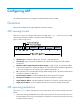
GRE tunnel operating principle Figure 54 IPv6 networks interconnected through a GRE tunnel As shown in Figure 54, an IPv6 protocol packet traverses an IPv4 network through a GRE tunnel as follows: 1. After receiving an IPv6 packet from the interface connected to IPv6 network 1, Device A looks up the routing table to determine that the outgoing interface is a GRE tunnel interface (Tunnel 0 in this example), and then submits the IPv6 packet to the tunnel interface Tunnel 0. 2.
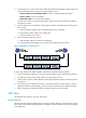
• You must configure the tunnel source address and destination address at both ends of a tunnel, and the tunnel source or destination address at one end must be the tunnel destination or source address at the other end. • HP recommends not configuring the same tunnel source and destination addresses for local tunnel interfaces that use the same GRE encapsulation protocol.
Step Command Remarks By default, no source address or interface is configured for a tunnel interface. 4. Configure a source address or source interface for the tunnel interface. source { ip-address | interface-type interface-number } If you configure a source address for a tunnel interface, the tunnel interface uses the source address as the source address of the encapsulated packets.
• You must configure the tunnel source address and destination address at both ends of a tunnel, and the tunnel source or destination address at one end must be the tunnel destination or source address at the other end. • HP recommends not configuring the same tunnel source and destination addresses for local tunnel interfaces that use the same GRE encapsulation protocol.
Step Command Remarks By default, no source IPv6 address or interface is configured for a tunnel interface. 4. Configure a source IPv6 address or source interface for the tunnel interface. source { ipv6-address | interface-type interface-number } If you configure a source IPv6 address for a tunnel interface, the tunnel interface uses the source IPv6 address as the source IPv6 address of the encapsulated packets.
Task Command Remarks Display IPv6 information about tunnel interface. display ipv6 interface [ tunnel [ number ] ] [ brief ] For more information about this command, see Layer 3—IP Services Command Reference. Clear tunnel interface statistics. reset counters interface [ tunnel [ number ] ] For more information about this command, see Layer 3—IP Services Command Reference.
# Configure the source address of tunnel interface as the IP address of VLAN-interface 101 on Switch A. [SwitchA-Tunnel1] source vlan-interface 101 # Configure the destination address of the tunnel interface as the IP address of VLAN-interface 101 on Switch B. [SwitchA-Tunnel1] destination 2.2.2.2 [SwitchA-Tunnel1] quit # Configure a static route from Switch A through the tunnel interface to Group 2. [SwitchA] ip route-static 10.1.3.0 255.255.255.0 tunnel 1 2.
Last clearing of counters: Never Last 300 seconds input rate: 0 bytes/sec, 0 bits/sec, 0 packets/sec Last 300 seconds output rate: 0 bytes/sec, 0 bits/sec, 0 packets/sec Input: 0 packets, 0 bytes, 0 drops Output: 0 packets, 0 bytes, 0 drops # Display tunnel interface information on Switch B. [SwitchB] display interface tunnel 1 Tunnel1 Current state: UP Line protocol state: UP Description: Tunnel1 Interface Bandwidth: 64kbps Maximum Transmit Unit: 1476 Internet Address is 10.1.2.
Figure 56 Network diagram Configuration procedure Before the following configurations, configure an IP address for each interface, and make sure Switch A and Switch B can reach each other. 1. Configure Switch A: # Create service loopback group 1, and configure the service type as tunnel. system-view [SwitchA] service-loopback group 1 type tunnel # Add port FortyGigE1/0/3 to service loopback group 1.
# Configure an IP address for the tunnel interface. [SwitchB-Tunnel0] ip address 10.1.2.2 255.255.255.0 # Configure the source address of tunnel interface as the IPv6 address of VLAN-interface 101 on Switch B. [SwitchB-Tunnel0] source 2001::2:1 # Configure the destination address of the tunnel interface as the IPv6 address of VLAN-interface 101 on Switch A. [SwitchB-Tunnel0] destination 2002::1:1 [SwitchB-Tunnel0] quit # Configure a static route from Switch B through the tunnel interface to Group 1.
Last 300 seconds output rate: 0 bytes/sec, 0 bits/sec, 0 packets/sec Input: 0 packets, 0 bytes, 0 drops Output: 0 packets, 0 bytes, 0 drops # From Switch B, ping the IP address of VLAN-interface 100 on Switch A. [SwitchB] ping -a 10.1.3.1 10.1.1.1 Ping 10.1.1.1 (10.1.1.1) from 10.1.3.1: 56 data bytes, press CTRL_C to break 56 bytes from 10.1.1.1: icmp_seq=0 ttl=255 time=2.000 ms 56 bytes from 10.1.1.1: icmp_seq=1 ttl=255 time=1.000 ms 56 bytes from 10.1.1.1: icmp_seq=2 ttl=255 time=1.
Solution 1. Execute the display ip routing-table command on Device A and Device C to view whether Device A has a route over tunnel 0 to 10.2.0.0/16 and whether Device C has a route over tunnel 0 to 10.1.0.0/16. 2. If such a route does not exist, execute the ip route-static command in system view to add the route. Take Device A as an example: [DeviceA] ip route-static 10.2.0.0 255.255.0.
Support and other resources Contacting HP For worldwide technical support information, see the HP support website: http://www.hp.
Conventions This section describes the conventions used in this documentation set. Command conventions Convention Description Boldface Bold text represents commands and keywords that you enter literally as shown. Italic Italic text represents arguments that you replace with actual values. [] Square brackets enclose syntax choices (keywords or arguments) that are optional. { x | y | ... } Braces enclose a set of required syntax choices separated by vertical bars, from which you select one.
Network topology icons Represents a generic network device, such as a router, switch, or firewall. Represents a routing-capable device, such as a router or Layer 3 switch. Represents a generic switch, such as a Layer 2 or Layer 3 switch, or a router that supports Layer 2 forwarding and other Layer 2 features. Represents an access controller, a unified wired-WLAN module, or the switching engine on a unified wired-WLAN switch. Represents an access point.
Index Numerics 6to4 tunnel, 114 applying DHCP address pool on interface, 33 ARP configuration, 1 tunnel configuration, 122, 123 displaying, 5 A dynamic entry aging timer configuration, 5 address dynamic entry max number max number (for device), 4 BOOTP client address acquisition (on interface), 70 dynamic entry max number max number (for interface), 4 DHCP address assignment, 22 DHCP address pool, 22 dynamic table entry, 2 DHCP address pool application on interface, 33 gratuitous ARP configurat
DHCP voice client Option 184 parameters, 31 B BIMS server information (DHCP client), 30 binding DHCP address pool static binding, 27 common DHCP options, 18 configuring ARP, 1 booting ARP (static), 6 DHCP client boot file name, 30 ARP dynamic entry aging timer, 5 BOOTP ARP static entry, 3 client address acquisition (on interface), 70 BOOTP client, 69, 70 client configuration, 69, 70 BOOTP client address acquisition (on interface), 70 client dynamic IP address acquisition, 69 DHCP address pool
IP services GRE/IPv4, 145 detecting IP services GRE/IPv4 tunnel, 140 DHCP client duplicated address detection, 55 IP services GRE/IPv6, 147 DHCP IP address conflict detection, 34 IP services GRE/IPv6 tunnel, 142 IPv6 ND duplicate address detection, 95 IP services ISATAP tunnel, 125, 126 IPv6 ND neighbor reachability detection, 95 IP services tunneling, 113, 118 IPv6 ND redirection, 96 IP services tunneling Layer 3 virtual interface, 118 IP services UDP helper, 87, 87, 88 IPv6 ND router/prefix d
TCP buffer size, 83 maintaining snooping, 66 TCP timer, 83 message format, 17 Option #, 18, See also Option # DHCP address assignment, 22 Option 121, 18 address pool, 22 Option 150, 18 address pool application on interface, 33 Option 184 (reserved), 18, 20 address pool selection, 23 Option 3;Option 003, 18 address pool static binding, 27 Option 33;Option 033, 18 BOOTP application, 69 Option 43 (vendor-specific);Option 043 (vendor-specific), 18, 18 BOOTP client address acquisition (on interfa
server configuration, 22, 24, 37 DHCP client configuration, 29 server enable on interface, 33 displaying IPv4 DNS, 75 server IP address dynamic assignment, 39 dynamic domain name resolution, 71 server IP address static assignment, 37 IPv4 client configuration, 73 server option customization configuration, 42 IPv4 client dynamic domain name resolution, 73, 76 server packet DSCP value, 36 IPv4 client static domain name resolution, 73, 76 server primary and secondary subnets configuration, 41 main
DHCP relay agent on interface, 47 F DHCP relay agent relay entry periodic refresh, 48 FIB displaying table entries, 80 DHCP relay agent relay entry recording, 48 DHCP relay agent starvation attack protection, 49 DHCP server on interface, 33 DHCP snooping starvation attack protection, 64 DHCP-REQUEST message attack protection, 64 directed broadcast receive/forward, 82 IP forwarding, 80 IP routing table, 80 file DHCP client boot file name, 30 FIN wait timer, 83 format ARP message format, 1 ICMP error pa
DHCP server address pool IP address range (primary subnet/multiple secondary subnets), 26 IPv6 ND protocol address resolution, 94 IPv6 ND redirection, 96 IPv6 ND router/prefix discovery, 95 DHCP server configuration, 37 IPv6 ND stateless address autoconfiguration, 95 DHCP server IP address dynamic assignment, 39 IP address class Host ID, 10 DHCP server option customization configuration, 42 DHCP server IP address static assignment, 37 ID DHCP server primary and secondary subnets configuration, 41
IPv6 ND stateless address autoconfiguration, 95 DHCP overview, 15 IPv6 ND static neighbor entry configuration, 101 DHCP relay agent configuration, 45, 46, 51 IPv6 path MTU discovery, 96 DHCP relay agent IP address release, 50 DHCP relay agent enable on interface, 47 IPv6 RA message parameter configuration, 103 DHCP relay agent Option 82 configuration, 50, 52 IPv6 transition technologies, 96 DHCP relay agent Option 82 support, 46 IPv6 tunneling technology, 97 DHCP relay agent relay entry periodic
IPv4/IPv4 tunnel configuration, 128, 129 IP-to-MAC IPv4/IPv4 tunneling, 115 IPv4/IPv6 tunnel configuration, 131, 132 DHCP snooping configuration, 59, 61 IPv4 IPv4/IPv6 tunneling, 116 6to4 tunnel configuration, 122, 123 IPv6 addresses, 91 DNS client configuration, 73 IPv6 anycast address configuration, 101 DNS configuration, 76 IPv6 basic settings configuration, 90, 97, 107 GRE encapsulation format, 139 IPv6 interface address assignment, 98 GRE/IPv4 configuration, 145 IPv6 link-local address co
interface link-local address automatic generation configuration, 100 IP services tunneling configuration, 113 IPv4/IPv6 de-encapsulation, 116 IPv4/IPv6 tunnel configuration, 131, 132 IPv4/IPv6 tunneling, 116 IPv6/IPv4 manual tunnel configuration, 119, 120 IPv6 tunneling, 114 ISATAP tunnel configuration, 125, 126 L LAN IP performance optimization, 82 Layer 3 BOOTP client configuration, 69, 70 IPv6/IPv4 tunnel types, 114 DHCP client configuration, 54, 56 IPv6/IPv4 tunneling, 113 DHCP overview, 15 IPv6/I
ARP, 5 neighbor discovery BOOTP client, 70 IPv6 duplicate address detection, 95 DHCP relay agent, 51 IPv6 ND address resolution, 94 DHCP server, 36 IPv6 ND configuration, 101 DHCP snooping, 66 IPv6 ND link-local entry minimization, 103 IP performance optimization, 86 IPv6 ND max number dynamic neighbor entries, 102 IP services tunneling configuration, 137 IPv6 ND protocol, 94 IP services UDP helper, 88 IPv6 ND stale state entry aging timer configuration, 102 IPv4 DNS, 75 IPv6 basics, 106 IP
IPv6 ND neighbor reachability detection, 95 DHCP server compatibility configuration, 35 DHCP server packet DSCP value, 36 IPv6 ND protocol, 94 DHCP server response broadcast, 35 IPv6 ND protocol address resolution, 94 DHCP server specification on relay agent, 47 IPv6 ND redirection, 96 DHCP snooping basic configuration, 61 IPv6 ND router/prefix discovery, 95 DHCP snooping trusted port, 59 IPv6 ND stale state entry aging timer configuration, 102 DHCP snooping untrusted port, 59 IPv6 ND stateless
IP services GRE/IPv6 configuration, 147 relay agent configuration, 50, 52 IP services tunneling configuration, 113, 118 relay agent support, 46 IP services UDP helper configuration, 87, 87, 88 snooping configuration, 62, 67 IPv4 DNS configuration, 76 snooping support, 60 IPv6 basic settings configuration, 90, 97, 107 node DHCP client NetBIOS node b (broadcast) type, 29 overlapping fragment attack, 85 P packet DHCP client packet DSCP value, 55 DHCP client NetBIOS node h (hybrid) type, 29 DHCP serv
IPv6 RA message parameter configuration, 103 configuring DHCP server IP address dynamic assignment, 39 IPv6 transition technologies, 96 configuring DHCP server IP address static assignment, 37 IPv6 tunneling technology, 97 IPv6/IPv4 tunneling, 113 configuring DHCP server option customization, 42 IPv6/IPv6 tunneling, 117 configuring DHCP server primary and secondary subnets, 41 parameter IPv6 RA message parameter, 104 configuring DHCP server response broadcast, 35 IPv6 RA message parameter configur
configuring IPv4/IPv6 tunnel, 131, 132 enabling DHCP relay agent on interface, 47 configuring IPv6 anycast address, 101 enabling DHCP relay agent relay entry periodic refresh, 48 configuring IPv6 basic settings, 97 enabling DHCP relay agent relay entry recording, 48 configuring IPv6 basic settings), 107 configuring IPv6 EUI-64 address, 98 enabling DHCP relay agent starvation attack protection, 49 configuring IPv6 global unicast address, 98 configuring IPv6 interface link-local address automatic gene
specifying DHCP server address pool IP address range (primary subnet/multiple ranges), 25 DHCP Option 82 support, 46 DHCP overview, 15 specifying DHCP server address pool IP address range (primary subnet/multiple secondary subnets), 26 DHCP relay agent packet DSCP value, 51 DHCP security functions, 48 DHCP server specification on relay agent, 47 specifying DHCP server on relay agent, 47 DHCP snooping configuration, 59, 61 specifying DNS interface, 75 displaying, 51 specifying DNS outgoing packet DSC
DHCP address pool IP address range (primary subnet/multiple ranges), 25 IP addressing subnetting, 11 IP forwarding, 80 DHCP address pool IP address range (primary subnet/multiple secondary subnets), 26 IP forwarding optimal route selection, 80 IP performance optimization, 82 DHCP client BIMS server information, 30 IP services GRE configuration, 139, 145 DHCP client gateway specification, 28 IP services GRE/IPv4 configuration, 145 DHCP client NetBIOS node type, 29 IP services GRE/IPv4 tunnel configu
displaying FIB table entries, 80 DHCP client domain name suffix, 29 DHCP client gateway, 28 TCP DHCP client server, 31 buffer size, 83 DHCP client TFTP server, 30 TCP timer configuration, 83 DHCP server address pool IP address range, 25 TCP/IP DHCP server address pool IP address range (primary subnet/multiple ranges), 25 DHCP server address pool IP address range (primary subnet/multiple secondary subnets), 26 DHCP server on relay agent, 47 DNS configuration, 71, 72 IPv4 DNS configuration, 76 TFTP
IPv4/IPv6 encapsulation, 116 DHCP server option customization configuration, 42 IPv4/IPv6 tunnel configuration, 131, 132 DHCP server user class configuration, 40 IPv4/IPv6 tunneling, 116 DHCP snooping basic configuration, 67 IPv6 tunneling technology, 97 DHCP snooping configuration, 67 IPv6/IPv4 manual tunnel configuration, 119, 120 IP services UDP helper configuration, 87, 87, 88 IPv6/IPv4 tunneling, 113 IPv6/IPv6 tunnel configuration, 134, 135 IPv6/IPv6 tunneling, 117 ISATAP tunnel configuration