HP FlexFabric 5930 Switch Series MCE Configuration Guide Part number: 5998-4625 Software version: Release 2406 & Release 2407P01 Document version: 6W101-20140404
Legal and notice information © Copyright 2014 Hewlett-Packard Development Company, L.P. No part of this documentation may be reproduced or transmitted in any form or by any means without prior written consent of Hewlett-Packard Development Company, L.P. The information contained herein is subject to change without notice.
Contents Configuring MCE ························································································································································· 1 MPLS L3VPN overview ····················································································································································· 1 Basic MPLS L3VPN architecture ······························································································································ 1
Configuring MCE This chapter describes MCE configuration. For information about the related routing protocols, see Layer 3—IP Routing Configuration Guide. MPLS L3VPN overview MPLS L3VPN is a L3VPN technology used to interconnect geographically dispersed VPN sites. MPLS L3VPN uses BGP to advertise VPN routes and uses MPLS to forward VPN packets over a service provider backbone. MPLS L3VPN provides flexible networking modes, excellent scalability, and convenient support for MPLS QoS and MPLS TE.
MPLS L3VPN concepts Site A site has the following features: • A site is a group of IP systems with IP connectivity that does not rely on any service provider network. • The classification of a site depends on the topology relationship of the devices, rather than the geographical positions, though the devices at a site are, in most cases, adjacent to each other geographically. • The devices at a site can belong to multiple VPNs, which means that a site can belong to multiple VPNs.
As shown in Figure 2, a VPN-IPv4 address consists of 12 bytes. The first eight bytes represent the RD, followed by a four-byte IPv4 prefix. The RD and the IPv4 prefix form a unique VPN-IPv4 prefix. An RD can be in one of the following formats: • When the Type field is 0, the Administrator subfield occupies two bytes, the Assigned number subfield occupies four bytes, and the RD format is 16-bit AS number:32-bit user-defined number. For example, 100:1.
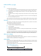
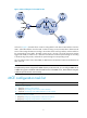
Figure 3 Network diagram for the MCE function As shown in Figure 3, the MCE device creates a routing table for each VPN. VLAN interface 2 binds to VPN 1 and VLAN-interface 3 binds to VPN 2. When receiving a route, the MCE device determines the source of the routing information according to the number of the receiving interface, and then adds it to the corresponding routing table. The MCE connects to PE 1 through a trunk link that permits packets tagged with VLAN 2 or VLAN 3.
Configuring VPN instances VPN instances isolate VPN routes from public network routes and routes among VPNs. You must configure VPN instances for an MCE network. Creating a VPN instance A VPN instance is a collection of the VPN membership and routing rules of its associated site. A VPN instance may not correspond to one VPN. To create and configure a VPN instance: Step Command Remarks 1. Enter system view. system-view N/A 2. Create a VPN instance and enter VPN instance view.
Configuring route related attributes for a VPN instance VPN routes are controlled and advertised on a PE by using the following process: 1. When a VPN route learned from a site gets redistributed into BGP, BGP associates it with a route target extended community attribute list, which is usually the export target attribute of the VPN instance associated with the site. 2. The VPN instance determines which routes it can accept and redistribute according to the import-extcommunity in the route target. 3.
Configuring routing on an MCE MCE implements service isolation through route isolation. MCE routing configuration includes the following: • MCE-VPN site routing configuration • MCE-PE routing configuration On the PE, disable routing loop detection to avoid route loss during route calculation, and disable route redistribution between routing protocols to save system resources.
Step 1. Enter system view. Command Remarks system-view N/A Perform this configuration on the MCE. On a VPN site, create a common OSPF process. 2. Create an OSPF process for a VPN instance and enter OSPF view. ospf [ process-id | router-id router-id | vpn-instance vpn-instance-name ] * An OSPF process bound to a VPN instance does not use the public network router ID configured in system view. Therefore, configure a router ID for the OSPF process.
Step Command Remarks By default, OSPF does not redistribute the default route. 7. (Optional.) Configure OSPF to redistribute the default route. default-route-advertise summary cost cost 8. Create an OSPF area and enter OSPF area view. area area-id By default, no OSPF area is created. 9. Enable OSPF on the interface attached to the specified network in the area. network ip-address wildcard-mask By default, an interface neither belongs to any area nor runs OSPF.
Step Command Remarks By default, BGP discards incoming route updates that contain the local AS number. Allow the local AS number to appear in the AS_PATH attribute of routes received from the peer, and set the maximum number of repetitions. peer { group-name | ip-address } allow-as-loop [ number ] 8. Redistribute remote site routes advertised by the PE into BGP.
1. Configure the MCE: Step Command Remarks 1. Enter system view. system-view N/A 2. Enter BGP view. bgp as-number N/A 3. Enter BGP-VPN instance view. ip vpn-instance vpn-instance-name N/A 4. Configure an IBGP peer. peer { group-name | ip-address } as-number as-number N/A 5. Enter BGP-VPN IPv4 unicast address family view. address-family ipv4 [ unicast ] N/A 6. Enable BGP to exchange IPv4 unicast routes with the peer.
Step 5. 6. Command Remarks Enable BGP to exchange IPv4 unicast routes with the peer. peer { group-name | ip-address } enable By default, BGP does not exchange IPv4 unicast routes with any peer. Redistribute the IGP routes of the VPN into BGP. import-route protocol [ { process-id | all-processes } [ allow-direct | med med-value | route-policy route-policy-name ] *] By default, no routes are redistributed into BGP. A VPN site must advertise VPN network addresses to the connected MCE.
Step Command Remarks By default, routing loop detection is enabled. 3. Disable routing loop detection. vpn-instance-capability simple 4. (Optional.) Configure the OSPF domain ID. domain-id domain-id [ secondary ] 5. (Optional.) Configure the type codes of OSPF extended community attributes. ext-community-type { domain-id type-code1 | router-id type-code2 | route-type type-code3 } You must disable routing loop detection for a VPN OSPF process on the MCE.
Step Command Remarks 12. Enable OSPF on the interface attached to the specified network in the area. network ip-address wildcard-mask By default, an interface neither belongs to any area nor runs OSPF. Configuring EBGP between an MCE and a PE Step Command Remarks 1. Enter system view. system-view N/A 2. Enter BGP view. bgp as-number N/A 3. Enter BGP-VPN instance view. ip vpn-instance vpn-instance-name N/A 4. Configure the PE as an EBGP peer.
For other MCE related displaying and maintaining commands, such as displaying routing table information for a VPN instance and maintaining routing sessions for a VPN instance, see Layer 3—IP Routing Command Reference. MCE configuration examples Configuring the MCE that uses OSPF to advertise VPN routes to the PE Network requirements As shown in Figure 4, the MCE device is connected to VPN 1 through VLAN-interface 10 and is connected to VPN 2 through VLAN-interface 20. OSPF runs in VPN 2.
system-view [MCE] ip vpn-instance vpn1 [MCE-vpn-instance-vpn1] route-distinguisher 10:1 [MCE-vpn-instance-vpn1] vpn-target 10:1 [MCE-vpn-instance-vpn1] quit [MCE] ip vpn-instance vpn2 [MCE-vpn-instance-vpn2] route-distinguisher 20:1 [MCE-vpn-instance-vpn2] vpn-target 20:1 [MCE-vpn-instance-vpn2] quit # Create VLAN 10, add port FortyGigE 1/0/1 to VLAN 10, and create VLAN-interface 10.
[VR1] ip route-static 0.0.0.0 0.0.0.0 10.214.10.3 # On the MCE, configure a static route to 192.168.0.0/24, specify the next hop as 10.214.10.2, and bind the static route with VPN instance vpn1. [MCE] ip route-static vpn-instance vpn1 192.168.0.0 24 10.214.10.2 # On the MCE, display the routing information maintained for VPN instance vpn1. [MCE] display ip routing-table vpn-instance vpn1 Destinations : 13 Routes : 13 Destination/Mask Proto 0.0.0.0/32 10.214.10.
Destination/Mask Proto 0.0.0.0/32 10.214.20.0/24 Pre Cost NextHop Interface Direct 0 0 127.0.0.1 InLoop0 Direct 0 0 10.214.20.3 Vlan20 10.214.20.0/32 Direct 0 0 10.214.20.3 Vlan20 10.214.20.3/32 Direct 0 0 127.0.0.1 InLoop0 10.214.20.255/32 Direct 0 0 10.214.20.3 Vlan20 127.0.0.0/8 Direct 0 0 127.0.0.1 InLoop0 127.0.0.0/32 Direct 0 0 127.0.0.1 InLoop0 127.0.0.1/32 Direct 0 0 127.0.0.1 InLoop0 127.255.255.255/32 Direct 0 0 127.0.0.1 InLoop0 192.168.10.
# On PE 1, create VLAN 30 and VLAN-interface 30, bind the VLAN interface with VPN instance vpn1, and configure an IP address for the VLAN interface. [PE1] vlan 30 [PE1-vlan30] quit [PE1] interface vlan-interface 30 [PE1-Vlan-interface30] ip binding vpn-instance vpn1 [PE1-Vlan-interface30] ip address 30.1.1.2 24 [PE1-Vlan-interface30] quit # On PE 1, create VLAN 40 and VLAN-interface 40, bind the VLAN interface with VPN instance vpn2, and configure an IP address for the VLAN interface.
0.0.0.0/32 Direct 0 0 127.0.0.1 InLoop0 30.1.1.0/24 Direct 0 0 30.1.1.2 Vlan30 30.1.1.0/32 Direct 0 0 30.1.1.2 Vlan30 30.1.1.2/32 Direct 0 0 127.0.0.1 InLoop0 30.1.1.255/32 Direct 0 0 30.1.1.2 Vlan30 127.0.0.0/8 Direct 0 0 127.0.0.1 InLoop0 127.0.0.0/32 Direct 0 0 127.0.0.1 InLoop0 127.0.0.1/32 Direct 0 0 127.0.0.1 InLoop0 127.255.255.255/32 Direct 0 0 127.0.0.1 InLoop0 192.168.0.0/24 OSPF 1 30.1.1.1 Vlan30 224.0.0.0/4 Direct 0 0 0.0.0.0 NULL0 224.0.0.
Figure 5 Network diagram Configuration procedure 1. Create VPN instances on the MCE and PE 1, and bind the VPN instances with VLAN interfaces. For the configuration procedure, see "Configure the VPN instances on the MCE and PE 1:." 2. Configure routing between the MCE and VPN sites: # Enable an OSPF process on the devices in the two VPNs, and advertise the subnets. (Details not shown.) # Configure OSPF on the MCE, and bind OSPF process 10 with VPN instance vpn1 to learn the routes of VPN 1.
10.214.10.0/32 Direct 0 0 10.214.10.3 Vlan10 10.214.10.3/32 Direct 0 0 127.0.0.1 InLoop0 10.214.10.255/32 Direct 0 0 10.214.10.3 Vlan10 127.0.0.0/8 Direct 0 0 127.0.0.1 InLoop0 127.0.0.0/32 Direct 0 0 127.0.0.1 InLoop0 127.0.0.1/32 Direct 0 0 127.0.0.1 InLoop0 127.255.255.255/32 Direct 0 0 127.0.0.1 InLoop0 192.168.0.0/24 OSPF 2 10.214.10.2 Vlan10 224.0.0.0/4 Direct 0 0 0.0.0.0 NULL0 224.0.0.0/24 Direct 0 0 0.0.0.0 NULL0 255.255.255.255/32 Direct 0 0 127.
[PE1] bgp 200 [PE1-bgp] ip vpn-instance vpn1 [PE1-bgp-vpn1] peer 30.1.1.1 as-number 100 [PE1-bgp-vpn1] address-family ipv4 [PE1-bgp-ipv4-vpn1] peer 30.1.1.1 enable [PE1-bgp-ipv4-vpn1] quit [PE1-bgp-vpn1] quit [PE1-bgp] quit # Use similar procedures to configure VPN 2 settings on MCE and PE 1. (Details not shown.) Verifying the configuration # Display the routing information for VPN 1 on PE 1.
255.255.255.255/32 Direct 0 0 127.0.0.1 InLoop0 Now, the MCE has redistributed the OSPF routes of the two VPN instances into the EBGP routing tables of PE 1.
Configuring IPv6 MCE This chapter describes IPv6 MCE configuration. Overview In MPLS L3VPN networks, MCE uses static routes or dynamic routing protocols to advertise IPv4 routes between internal networks and PEs and forwards IPv4 packets. In IPv6 MPLS L3VPN networks, IPv6 MCE uses IPv6 static routes and dynamic routing protocols to advertise IPv6 routes between internal networks and PEs and forwards IPv6 packets. The fundamentals of IPv6 MCE are the same as those of MCE.
Step 4. 5. Command Remarks By default, no description is configured for a VPN instance. (Optional.) Configure a description for the VPN instance. description text (Optional.) Configure an ID for the VPN instance. vpn-id vpn-id The description should contain the VPN instance's related information, such as its relationship with a certain VPN. By default, no ID is configured for a VPN instance.
Step 2. Enter VPN instance view or IPv6 VPN view. Command Remarks • Enter VPN instance view: Configurations made in VPN instance view apply to both IPv4 VPN and IPv6 VPN. ip vpn-instance vpn-instance-name • Enter IPv6 VPN view: address-family ipv6 3. 4. Configure route targets. Set the maximum number of active routes supported.
• On the MCE, configure VPN instances, and bind the VPN instances with the interfaces connected to the VPN sites and those connected to the PE. • Configure the link layer and network layer protocols on related interfaces to ensure IP connectivity. Configuring routing between an MCE and a VPN site You can configure static routing, OSPFv3, EBGP, or IBGP between an MCE and a VPN site. Configuring static routing between an MCE and a VPN site An MCE can reach a VPN site through an IPv6 static route.
Step Command Remarks By default, no routes are redistributed into OSPFv3. 4. Redistribute remote site routes advertised by the PE. import-route protocol [ process-id | all-processes | allow-ibgp ] [ allow-direct | cost cost | route-policy route-policy-name | type type ] * 5. Return to system view. quit N/A 6. Enter interface view. interface interface-type interface-number N/A 7. Enable OSPFv3 on the interface.
Step Command Remarks 2. Enter BGP view. bgp as-number N/A 3. Configure the MCE as an EBGP peer. peer { group-name | ipv6-address } as-number as-number By default, no BGP peer is configured. 4. Enter BGP IPv6 unicast address family view. address-family ipv6 [ unicast ] N/A 5. Enable BGP to exchange IPv6 unicast routes with the specified peer. peer { group-name | ip-address } enable By default, BGP does not exchange IPv6 unicast routes with any peer. Redistribute the IGP routes of the VPN.
Step Remarks 8. Redistribute remote site routes advertised by the PE into BGP. import-route protocol [ process-id [ allow-direct | med med-value | route-policy route-policy-name ] * ] By default, no routes are redistributed into BGP. 9. (Optional.) Configure filtering of advertised routes. filter-policy { acl6-number | prefix-list ipv6-prefix-name } export [ protocol process-id ] By default, BGP does not filter advertised routes.
Step Command Remarks By default, no IPv6 static route is configured. The default value is 60. 2. Configure an IPv6 static route for an IPv6 VPN instance. ipv6 route-static vpn-instance s-vpn-instance-name ipv6-address prefix-length { interface-type interface-number [ next-hop-address ] | nexthop-address [ public ] | vpn-instance d-vpn-instance-name nexthop-address } [ permanent ] [ preference preference-value ] [ tag tag-value ] [ description description-text ] 3. (Optional.
Step Command Remarks 6. Enable BGP to exchange IPv6 unicast routes with the specified peer. peer { group-name | ip-address } enable By default, BGP does not exchange IPv6 unicast routes with any peer. 7. Redistribute VPN routes. import-route protocol [ process-id [ allow-direct | med med-value | route-policy route-policy-name ] * ] By default, no routes are redistributed into BGP. 8. (Optional.) Configure filtering of advertised routes.
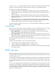
Figure 6 Network diagram VPN 2 Site 1 CE PE 2 PE 1 FGE1/0/1 Vlan-int30: 30::2/64 Vlan-int40: 40::2/64 VPN 1 2012:1::/64 Vlan-int11 2012:1::2/64 VR 1 Vlan-int10 2001:1::2/64 FGE1/0/1 Vlan-int10 2001:1::1/64 MCE FGE1/0/3 Vlan-int30: 30::1/64 Vlan-int40: 40::1/64 FGE1/0/2 Vlan-int20 2002:1::1/64 PE 3 CE VPN 1 Site 2 Vlan-int20 2002:1::2/64 VR 2 Vlan-int21 2012::2/64 VPN 2 2012::/64 Configuration procedure Assume that the system name of the MCE device is MCE, the system names of the edge devices of
# Bind VLAN-interface 10 with VPN instance vpn1, and configure an IPv6 address for the VLAN interface. [MCE] interface vlan-interface 10 [MCE-Vlan-interface10] ip binding vpn-instance vpn1 [MCE-Vlan-interface10] ipv6 address 2001:1::1 64 [MCE-Vlan-interface10] quit # Configure VLAN 20, add port FortyGigE 1/0/2 to VLAN 20, bind VLAN-interface 20 with VPN instance vpn2, and assign an IPv6 address to VLAN-interface 20.
[MCE-Vlan-interface20] ospfv3 30 area 0.0.0.0 [MCE-Vlan-interface20] quit # On VR 2, assign IPv6 address 2002:1::2/64 to the interface connected to the MCE, 2012::2/64 to the interface connected to VPN 2, and 102.102.10.1 to Loopback 0. (Details not shown.) # Enable OSPFv3 process 30, and enable OSPFv3 on VLAN-interface 20 and VLAN-interface 21. system-view [VR2] ospfv3 30 [MCE-ospfv3-30] router-id 102.102.10.
Destination: ::1/128 Protocol : Direct NextHop : ::1 Preference: 0 Interface : InLoop0 Cost : 0 Destination: 2002:1::/64 Protocol : Direct NextHop : :: Preference: 0 Interface : Vlan20 Cost : 0 Destination: 2002:1::1/128 Protocol : Direct NextHop : ::1 Preference: 0 Interface : InLoop0 Cost : 0 Destination: 2012::/64 Protocol : OSPFv3 NextHop : FE80::20C:29FF:FE40:701 Preference: 150 Interface : Vlan20 Cost : 1 Destination: FE80::/10 Protocol : Direct NextHop : ::
# On the MCE, create VLAN 40 and VLAN-interface 40, bind VLAN-interface 40 with VPN instance vpn2, and configure an IPv6 address for the VLAN-interface 40. [MCE] vlan 40 [MCE-vlan40] quit [MCE] interface vlan-interface 40 [MCE-Vlan-interface40] ip binding vpn-instance vpn2 [MCE-Vlan-interface40] ipv6 address 40::1 64 [MCE-Vlan-interface40] quit # On PE 1, create VLAN 30 and VLAN-interface 30, bind VLAN-interface 30 with VPN instance vpn1, and configure an IPv6 address for the VLAN-interface 30.
Verifying the configuration # Display the routing table for VPN instance vpn1. The output shows that PE 1 has learned the private route of VPN 1 through OSPFv3.
Destination: 2012::/64 Protocol NextHop : FE80::200:FF:FE0F:5 Preference: 150 : OSPFv3 Interface : Vlan40 Cost : 1 Destination: FE80::/10 Protocol : Direct NextHop : :: Preference: 0 Interface : NULL0 Cost : 0 Destination: FF00::/8 Protocol : Direct NextHop : :: Preference: 0 Interface : NULL0 Cost : 0 Now, the routing information for the two VPNs has been added into the routing tables on PE 1.
Support and other resources Contacting HP For worldwide technical support information, see the HP support website: http://www.hp.
Conventions This section describes the conventions used in this documentation set. Command conventions Convention Description Boldface Bold text represents commands and keywords that you enter literally as shown. Italic Italic text represents arguments that you replace with actual values. [] Square brackets enclose syntax choices (keywords or arguments) that are optional. { x | y | ... } Braces enclose a set of required syntax choices separated by vertical bars, from which you select one.
Network topology icons Represents a generic network device, such as a router, switch, or firewall. Represents a routing-capable device, such as a router or Layer 3 switch. Represents a generic switch, such as a Layer 2 or Layer 3 switch, or a router that supports Layer 2 forwarding and other Layer 2 features. Represents an access controller, a unified wired-WLAN module, or the switching engine on a unified wired-WLAN switch. Represents an access point.
Index A IPv6 MPLS L3VPN MCE-VPN site routing, 28 address IPv6 MPLS L3VPN MCE-VPN site static routing, 28 IPv6 MPLS L3VPN VPN instance, 25 MPLS L3VPN address space overlapping, 2 IPv6 MPLS L3VPN VPN instance route related attributes, 26 architecture MPLS L3VPN, 1 MCE, 15 associating MPLS L3VPN MCE, 1 IPv6 MPLS L3VPN VPN instance with interface, 26 MPLS L3VPN MCE routing, 7 MPLS L3VPN MCE-PE, 20 MPLS L3VPN VPN instance with interface, 5 MPLS L3VPN MCE-PE EBGP, 14 attribute MPLS L3VPN MCE-PE OSP
MPLS L3VPN MCE-VPN site configuration, 15 MCE-PE configuration, 31 provider device. See MCE-PE EBGP configuration, 32 provider edge device.
IPv6 MPLS L3VPN MCE-VPN site EBGP configuration, 29 MCE-VPN site routing configuration, 7 MCE-VPN site static routing configuration, 7 IPv6 MPLS L3VPN MCE-VPN site IBGP configuration, 30 MPLS L3VPN MCE-PE configuration, 20 MPLS L3VPN MCE-VPN site configuration, 15 IPv6 MPLS L3VPN MCE-VPN site OSPFv3 configuration, 28 multi-VPN instance, 1, 3 routing configuration, 7 IPv6 MPLS L3VPN MCE-VPN site routing configuration, 28 MPLS L3VPN address space overlapping, 2 IPv6 MPLS L3VPN MCE-VPN site static rout
associating IPv6 MPLS L3VPN VPN instance with interface, 26 MPLS L3VPN MCE-PE configuration, 20 MPLS L3VPN MCE-VPN site configuration, 15 associating MPLS L3VPN VPN instance with interface, 5 O OSPF configuring IPv6 MCE, 33 MPLS L3VPN MCE-PE OSPF configuration, 12 configuring IPv6 MPLS L3VPN MCE routing, 27 MPLS L3VPN MCE-VPN site configuration, 15 configuring IPv6 MPLS L3VPN MCE-PE, 31 MPLS L3VPN MCE-VPN site OSPF configuration, 7 configuring IPv6 MPLS L3VPN MCE-PE EBGP, 32 configuring IPv6 MPLS
IPv6 MPLS L3VPN VPN instance route related attributes, 26 maintaining MCE, 14 provider device. See MCE configuration, 15 edge device.