HP FlexFabric 5930 Switch Series Network Management and Monitoring Configuration Guide Part number: 5998-4627 Software version: Release 2406 & Release 2407P01 Document version: 6W101-20140404
Legal and notice information © Copyright 2014 Hewlett-Packard Development Company, L.P. No part of this documentation may be reproduced or transmitted in any form or by any means without prior written consent of Hewlett-Packard Development Company, L.P. The information contained herein is subject to change without notice.
Contents Using ping, tracert, and system debugging ··············································································································· 1 Ping ····················································································································································································· 1 Using a ping command to test network connectivity ···························································································· 1 Ping example
Configuration example for NTP broadcast mode with authentication ····································································· 45 Configuration example for MPLS VPN time synchronization in client/server mode ·············································· 48 Configuration example for MPLS VPN time synchronization in symmetric active/passive mode ························· 49 Configuring SNTP ··············································································································
Configuring port mirroring ········································································································································ 84 Overview········································································································································································· 84 Terminology ························································································································································
Subscription service ············································································································································ 109 Related information ······················································································································································ 109 Documents ···························································································································································· 109
Using ping, tracert, and system debugging This chapter covers ping, tracert, and information about debugging the system. Ping Use the ping utility to determine if a specific address is reachable. Ping sends ICMP echo requests (ECHO-REQUEST) to the destination device. Upon receiving the requests, the destination device responds with ICMP echo replies (ECHO-REPLY) to the source device.
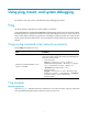
Figure 1 Network diagram Configuration procedure # Use the ping command on Device A to test connectivity to Device C. Ping 1.1.2.2 (1.1.2.2): 56 data bytes, press CTRL_C to break 56 bytes from 1.1.2.2: icmp_seq=0 ttl=254 time=2.137 ms 56 bytes from 1.1.2.2: icmp_seq=1 ttl=254 time=2.051 ms 56 bytes from 1.1.2.2: icmp_seq=2 ttl=254 time=1.996 ms 56 bytes from 1.1.2.2: icmp_seq=3 ttl=254 time=1.963 ms 56 bytes from 1.1.2.2: icmp_seq=4 ttl=254 time=1.991 ms --- Ping statistics for 1.1.2.
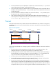
2. The intermediate device (Device B) adds the IP address of its outbound interface (1.1.2.1) to the RR option of the ICMP echo request, and forwards the packet. 3. Upon receiving the request, the destination device copies the RR option in the request and adds the IP address of its outbound interface (1.1.2.2) to the RR option. Then the destination device sends an ICMP echo reply. 4. The intermediate device adds the IP address of its outbound interface (1.1.1.
6. The source device thinks that the packet has reached the destination device after receiving the port-unreachable ICMP message, and the path to the destination device is 1.1.1.2 to 1.1.2.2 to 1.1.3.2. Prerequisites Before you use a tracert command, perform the tasks in this section. For an IPv4 network: • Enable sending of ICMP timeout packets on the intermediate devices (devices between the source and destination devices).
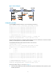
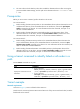
Figure 3 Network diagram 1.1.1.1/24 1.1.1.2/24 Device A 1.1.2.1/24 1.1.2.2/24 Device B Device C Configuration procedure 1. Configure the IP addresses for devices as shown in Figure 3. 2. Configure a static route on Device A. system-view [DeviceA] ip route-static 0.0.0.0 0.0.0.0 1.1.1.2 [DeviceA] quit 3. Use the ping command to test connectivity between Device A and Device C. ping 1.1.2.2 Ping 1.1.2.2(1.1.2.
System debugging The device supports debugging for the majority of protocols and features and provides debugging information to help users diagnose errors. Debugging information control switches The following switches control the display of debugging information: • Module debugging switch—Controls whether to generate the module-specific debugging information. • Screen output switch—Controls whether to display the debugging information on a certain screen.
Step Command Remarks 1. Enable debugging for a specified module in user view. debugging { all [ timeout time ] | module-name [ option ] } By default, all debugging functions are disabled. 2. (Optional.) Display the enabled debugging in any view.
Configuring NTP Synchronize your device with a trusted time source by using the Network Time Protocol (NTP) or changing the system time before you run it on a live network. Various tasks, including network management, charging, auditing, and distributed computing depend on an accurate system time setting, because the timestamps of system messages and logs use the system time. Overview NTP is typically used in large networks to dynamically synchronize time among network devices.
The synchronization process is as follows: 1. Device A sends Device B an NTP message, which is timestamped when it leaves Device A. The time stamp is 10:00:00 am (T1). 2. When this NTP message arrives at Device B, Device B adds a timestamp showing the time when the message arrived at Device B. The timestamp is 11:00:01 am (T2). 3. When the NTP message leaves Device B, Device B adds a timestamp showing the time when the message left Device B. The timestamp is 11:00:02 am (T3). 4.
To ensure time accuracy and availability, you can specify multiple NTP servers for a device. The device selects an optimal NTP server as the clock source based on parameters such as stratum. The clock that the device selects is called the reference source. For more information about clock selection, see the related protocols and standards.
Mode Working process Principle Application scenario A symmetric active peer and a symmetric passive peer can be synchronized to each other. If both of them are synchronized, the peer with a higher stratum is synchronized to the peer with a lower stratum. As Figure 6 shows, this mode is most often used between two or more servers with the same stratum to operate as a backup for one another.
NTP security To improve time synchronization security, NTP provides the access control and authentication functions. NTP access control You can control NTP access by using an ACL. The access rights are in the following order, from least restrictive to most restrictive: • Peer—Allows time requests and NTP control queries (such as alarms, authentication status, and time server information) and allows the local device to synchronize itself to a peer device.
in the NTP message. If they are the same, the receiver accepts the message. Otherwise, it discards the message. NTP for MPLS VPNs The device supports multiple VPN instances when it functions as an NTP client or a symmetric active peer to realize time synchronization with the NTP server or symmetric passive peer in an MPLS VPN network. Only the client/server and symmetric active/passive modes support VPN instances.
Configuration task list Tasks at a glance (Required.) Enabling the NTP service (Required.) Perform at least one of the following tasks: • Configuring NTP association modes • Configuring the local clock as a reference source (Optional.) Configuring access control rights (Optional.) Configuring NTP authentication (Optional.) Configuring NTP optional parameters Enabling the NTP service Step Command Remarks 1. Enter system view. system-view N/A 2. Enable the NTP service.
Step Command Remarks • Specify an NTP server for the Specify an NTP server for the device. 2. device: ntp-service unicast-server { server-name | ip-address } [ vpn-instance vpn-instance-name ] [ authentication-keyid keyid | priority | source interface-type interface-number | version number ] * • Specify an IPv6 NTP server for By default, no NTP server is specified for the device.
Step Command Remarks • Specify a symmetric-passive 2. Specify a symmetric-passive peer for the device. peer: ntp-service unicast-peer { peer-name | ip-address } [ vpn-instance vpn-instance-name ] [ authentication-keyid keyid | priority | source interface-type interface-number | version number ] * • Specify an IPv6 By default, no symmetric-passive peer is specified.
Step 3. Command Configure the device to operate in NTP broadcast server mode. ntp-service broadcast-server [ authentication-keyid keyid | version number ] * Remarks By default, the device does not operate in broadcast server mode. After you execute the command, the device receives NTP broadcast messages from the specified interface.
Step Command Remarks • Configure the device to operate 3. Configure the device to operate in multicast server mode. in multicast server mode: ntp-service multicast-server [ ip-address ] [ authentication-keyid keyid | ttl ttl-number | version number ] * • Configure the device to operate in multicast server mode: ntp-service ipv6 multicast-server ipv6-multicast-address [ authentication-keyid keyid | ttl ttl-number ] * By default, the device does not operate in multicast server mode.
NTP server on the client. The key IDs and key values configured on the server and client must be the same. Otherwise, NTP authentication fails. To configure NTP authentication for a client: Step Command Remarks 1. Enter system view. system-view N/A 2. Enable NTP authentication. ntp-service authentication enable By default, NTP authentication is disabled. 3. Configure an NTP authentication key.
Table 2 NTP authentication results Client Enable NTP authenticati on Yes Yes Yes Yes Yes No Server Configure a key and configure it as a trusted key Yes Yes Yes No N/A N/A Associate the key with an NTP server Yes Enable NTP authenticati on Yes Yes Yes Yes No Yes N/A No N/A N/A N/A Configure a key and configure it as a trusted key Authentication result Yes Succeeded. NTP messages can be sent and received correctly. No Failed. NTP messages cannot be sent and received correctly.
Step Command Remarks 3. Configure an NTP authentication key. ntp-service authentication-keyid keyid authentication-mode md5 { cipher | simple } value By default, no NTP authentication key is configured. 4. Configure the key as a trusted key. ntp-service reliable authentication-keyid keyid By default, no authentication key is configured as a trusted key. • Associate the specified key with 5. Associate the specified key with a passive peer.
Active peer Passive peer Enable NTP authentic ation Configure a key and configure it as a trusted key Associate the key with an passive peer Enable NTP authentication Configure a key and configure it as a trusted key Yes Yes Yes Yes No Failed. NTP messages cannot be sent and received correctly. Yes Yes Yes No N/A Failed. NTP messages cannot be sent and received correctly. Yes N/A No Yes N/A Failed. NTP messages cannot be sent and received correctly.
Step Command Remarks 1. Enter system view. system-view N/A 2. Enable NTP authentication. ntp-service authentication enable By default, NTP authentication is disabled. 3. Configure an NTP authentication key. ntp-service authentication-keyid keyid authentication-mode md5 { cipher | simple } value By default, no NTP authentication key is configured. 4. Configure the key as a trusted key.
Broadcast server Broadcast client Enable NTP authentic ation Configure a key and configure it as a trusted key Associate the key with a broadcast server Enable NTP authenticati on Configure a key and configure it as a trusted key Yes No Yes No N/A No authentication. NTP messages can be sent and received correctly. Yes N/A No Yes N/A Failed. NTP messages cannot be sent and received correctly. Yes N/A No No N/A No authentication. NTP messages can be sent and received correctly.
Step Command Remarks 3. Configure an NTP authentication key. ntp-service authentication-keyid keyid authentication-mode md5 { cipher | simple } value By default, no NTP authentication key is configured. 4. Configure the key as a trusted key. ntp-service reliable authentication-keyid keyid By default, no authentication key is configured as a trusted key. 5. Enter interface view. interface interface-type interface-number N/A • Associate the specified key with 6.
Multicast server Enable NTP authentic ation Yes Yes Yes No No Configure a key and configure it as a trusted key No N/A N/A N/A N/A Multicast client Associate the key with a multicast server Yes Enable NTP authenticatio n No No Yes No No N/A Yes N/A No Configure a key and configure it as a trusted key Authentication result N/A No authentication. NTP messages can be sent and received correctly. N/A Failed. NTP messages cannot be sent and received correctly. N/A No authentication.
To specify the source interface for NTP messages: Step Enter system view. 1. Command Remarks system-view N/A • Specify the source interface for Specify the source interface for NTP messages. 2. NTP messages: ntp-service source-interface interface-type interface-number • Specify the source interface for By default, no source interface is specified for NTP messages.
A single device can have a maximum of 128 concurrent associations, including static associations and dynamic associations. Perform this task to restrict the number of dynamic associations to prevent dynamic associations from occupying too many system resources. To configure the maximum number of dynamic associations: Step Command Remarks 1. Enter system view. system-view N/A 2. Configure the maximum number of dynamic sessions allowed to be established.
Displaying and maintaining NTP Execute display commands in any view. Task Command Display information about NTP service status. display ntp-service status Display information about IPv4 NTP associations. display ntp-service sessions [ verbose ] Display information about IPv6 NTP associations. display ntp-service ipv6 sessions [ verbose ] Display brief information about the NTP servers from the local device back to the primary reference source.
System peer: 1.0.1.11 Local mode: client Reference clock ID: 1.0.1.11 Leap indicator: 00 Clock jitter: 0.000977 s Stability: 0.000 pps Clock precision: 2^-10 Root delay: 0.00383 ms Root dispersion: 16.26572 ms Reference time: d0c6033f.b9923965 Wed, Dec 29 2010 18:58:07.724 The output shows that Device B has been synchronized to Device A, the clock stratum level of Device B is 3, and that of Device A is 2. # Display IPv4 NTP association information for Device B.
# Enable the NTP service. system-view [DeviceB] ntp-service enable # Specify Device A as the IPv6 NTP server of Device B so that Device B is synchronized to Device A. [DeviceB] ntp-service ipv6 unicast-server 3000::34 4. Verify the configuration: # Display the NTP status of Device B after clock synchronization. [DeviceB] display ntp-service status Clock status: synchronized Clock stratum: 3 System peer: 3000::34 Local mode: client Reference clock ID: 163.29.247.
• Configure Device C to operate in symmetric-active mode and specify Device B as the passive peer of Device C. Figure 11 Network diagram Configuration procedure 1. Set the IP address for each interface as shown in Figure 11. (Details not shown.) 2. Configure Device A: # Enable the NTP service. system-view [DeviceA] ntp-service enable # Specify the local clock as the reference source, with the stratum level 3. [DeviceA] ntp-service refclock-master 3 3.
Clock status: synchronized Clock stratum: 3 System peer: 3.0.1.33 Local mode: sym_passive Reference clock ID: 3.0.1.33 Leap indicator: 00 Clock jitter: 0.000916 s Stability: 0.000 pps Clock precision: 2^-17 Root delay: 0.00609 ms Root dispersion: 1.95859 ms Reference time: 83aec681.deb6d3e5 Sun, Jan 4 1970 5:56:17.869 # Display IPv4 NTP association information for Device B.
Figure 12 Network diagram Configuration procedure 1. Set the IP address for each interface as shown in Figure 12. (Details not shown.) 2. Configure Device A: # Enable the NTP service. system-view [DeviceA] ntp-service enable # Specify the local clock as the reference source, with the stratum level 3. [DeviceA] ntp-service refclock-master 3 3. Configure Device B: # Enable the NTP service.
Clock stratum: 3 System peer: 3000::36 Local mode: sym_passive Reference clock ID: 163.29.247.19 Leap indicator: 11 Clock jitter: 0.000977 s Stability: 0.000 pps Clock precision: 2^-10 Root delay: 0.01855 ms Root dispersion: 9.23483 ms Reference time: d0c6047c.97199f9f Wed, Dec 29 2010 19:03:24.590 # Display IPv6 NTP association information for Device B. [DeviceB] display ntp-service ipv6 sessions Notes: 1 source(master), 2 source(peer), 3 selected, 4 candidate, 5 configured.
Figure 13 Network diagram Configuration procedure 1. Set the IP address for each interface as shown in Figure 13. (Details not shown.) 2. Configure Switch C: # Enable the NTP service. system-view [SwitchC] ntp-service enable # Specify the local clock as the reference source, with the stratum level 2. [SwitchC] ntp-service refclock-master 2 # Configure Switch C to operate in broadcast server mode and send broadcast messages through VLAN-interface 2.
# Switch A and Switch B get synchronized upon receiving a broadcast message from Switch C. Display the NTP status of Switch A after clock synchronization. [SwitchA-Vlan-interface2] display ntp-service status Clock status: synchronized Clock stratum: 3 System peer: 3.0.1.31 Local mode: bclient Reference clock ID: 3.0.1.31 Leap indicator: 00 Clock jitter: 0.044281 s Stability: 0.000 pps Clock precision: 2^-10 Root delay: 0.00229 ms Root dispersion: 4.12572 ms Reference time: d0d289fe.
Figure 14 Network diagram Vlan-int2 3.0.1.31/24 Switch C NTP multicast server Vlan-int3 1.0.1.11/24 Vlan-int3 1.0.1.10/24 Switch A NTP multicast client Vlan-int2 3.0.1.30/24 Switch B Vlan-int2 3.0.1.32/24 Switch D NTP multicast client Configuration procedure 1. Set the IP address for each interface as shown in Figure 14. (Details not shown.) 2. Configure Switch C: # Enable the NTP service.
Leap indicator: 00 Clock jitter: 0.044281 s Stability: 0.000 pps Clock precision: 2^-10 Root delay: 0.00229 ms Root dispersion: 4.12572 ms Reference time: d0d289fe.ec43c720 Sat, Jan 8 2011 7:00:14.922 The output shows that Switch D has been synchronized to Switch C, the clock stratum level of Switch D is 3, and that of Switch C is 2. # Display IPv4 NTP association information for Switch D.
7. Verify the configuration: # Display the NTP status of Switch A after clock synchronization. [SwitchA-Vlan-interface3] display ntp-service status Clock status: synchronized Clock stratum: 3 System peer: 3.0.1.31 Local mode: bclient Reference clock ID: 3.0.1.31 Leap indicator: 00 Clock jitter: 0.165741 s Stability: 0.000 pps Clock precision: 2^-10 Root delay: 0.00534 ms Root dispersion: 4.51282 ms Reference time: d0c61289.10b1193f Wed, Dec 29 2010 20:03:21.
Figure 15 Network diagram Configuration procedure 1. Set the IP address for each interface as shown in Figure 15. (Details not shown.) 2. Configure Switch C: # Enable the NTP service. system-view [SwitchC] ntp-service enable # Specify the local clock as the reference source, with the stratum level 2. [SwitchC] ntp-service refclock-master 2 # Configure Switch C to operate in IPv6 multicast server mode and send multicast messages through VLAN-interface 2.
Leap indicator: 00 Clock jitter: 0.000977 s Stability: 0.000 pps Clock precision: 2^-10 Root delay: 0.00000 ms Root dispersion: 8.00578 ms Reference time: d0c60680.9754fb17 Wed, Dec 29 2010 19:12:00.591 The output shows that Switch D has been synchronized to Switch C, the clock stratum level of Switch D is 3, and that of Switch C is 2. # Display NTP association information for Switch D.
# Configure Switch A to operate in IPv6 multicast client mode and receive IPv6 multicast messages on VLAN-interface 3. [SwitchA] interface vlan-interface 3 [SwitchA-Vlan-interface3] ntp-service ipv6 multicast-client ff24::1 7. Verify the configuration: # Display the NTP status of Switch A after clock synchronization. [SwitchA-Vlan-interface3] display ntp-service status Clock status: synchronized Clock stratum: 3 System peer: 3000::2 Local mode: bclient Reference clock ID: 165.84.121.
Figure 16 Network diagram Configuration procedure 1. Set the IP address for each interface as shown in Figure 16. (Details not shown.) 2. Configure Device A: # Enable the NTP service. system-view [DeviceA] ntp-service enable # Specify the local clock as the reference source, with the stratum level 2. [DeviceA] ntp-service refclock-master 2 3. Configure Device B: # Enable the NTP service. system-view [DeviceB] ntp-service enable # Enable NTP authentication on Device B.
Reference clock ID: 1.0.1.11 Leap indicator: 00 Clock jitter: 0.005096 s Stability: 0.000 pps Clock precision: 2^-10 Root delay: 0.00655 ms Root dispersion: 1.15869 ms Reference time: d0c62687.ab1bba7d Wed, Dec 29 2010 21:28:39.668 The output shows that Device B has been synchronized to Device A, the clock stratum level of Device B is 3, and that of Device A is 2. # Display IPv4 NTP association information for Device B.
Figure 17 Network diagram Vlan-int2 3.0.1.31/24 Switch C NTP broadcast server Vlan-int2 3.0.1.30/24 Switch A NTP broadcast client Vlan-int2 3.0.1.32/24 Switch B NTP broadcast client Configuration procedure 1. Set the IP address for each interface as shown in Figure 17. (Details not shown.) 2. Configure Switch A: # Enable the NTP service. system-view [SwitchA] ntp-service enable # Enable NTP authentication on Switch A.
system-view [SwitchC] ntp-service enable # Specify the local clock as the reference source, with the stratum level 3. [SwitchC] ntp-service refclock-master 3 # Configure Switch C to operate in NTP broadcast server mode and use VLAN-interface 2 to send NTP broadcast packets. [SwitchC] interface vlan-interface 2 [SwitchC-Vlan-interface2] ntp-service broadcast-server [SwitchC-Vlan-interface2] quit 5.
source reference stra reach poll now offset delay disper ******************************************************************************** [1245]3.0.1.31 127.127.1.0 3 3 64 68 -0.0 0.0000 0.0 Notes: 1 source(master),2 source(peer),3 selected,4 candidate,5 configured. Total sessions : 1 The output shows that an association has been set up between Switch B and Switch C.
# Enable the NTP service. system-view [PE2] ntp-service enable # Specify CE 1 in VPN 1 as the NTP server of PE 2. [PE2] ntp-service unicast-server 10.1.1.1 vpn-instance vpn1 4. Verify the configuration: # Display the IPv4 NTP association information and status on PE 2 a certain period of time later. [PE2] display ntp-service status Clock status: synchronized Clock stratum: 3 System peer: 10.1.1.1 Local mode: client Reference clock ID: 10.1.1.1 Leap indicator: 00 Clock jitter: 0.
Figure 19 Network diagram Configuration procedure 1. Set the IP address for each interface as shown in Figure 19. (Details not shown.) 2. Configure CE 1: # Enable the NTP service. system-view [CE1] ntp-service enable # Specify the local clock as the reference source, with the stratum level 2. [CE1] ntp-service refclock-master 2 3. Configure PE 1: # Enable the NTP service. system-view [PE1] ntp-service enable # Specify CE 1 in VPN 1 as the symmetric-passive peer of PE 1.
[PE1] display ntp-service sessions source reference stra reach poll now offset delay disper ******************************************************************************** [1245]10.1.1.1 127.127.1.0 2 1 64 519 -0.0 0.0000 Notes: 1 source(master),2 source(peer),3 selected,4 candidate,5 configured. Total sessions : 1 [PE1] display ntp-service trace Server 127.0.0.1 Stratum 3 , jitter Server 10.1.1.1 Stratum 2 , jitter 939.00, synch distance 0.0000. RefID 127.127.1.0 0.
Configuring SNTP SNTP is a simplified, client-only version of NTP specified in RFC 4330. SNTP supports only the client/server mode. An SNTP-enabled device can receive time from NTP servers, but cannot provide time services to other devices. SNTP uses the same packet format and packet exchange procedure as NTP, but provides faster synchronization at the price of time accuracy. If you specify multiple NTP servers for an SNTP client, the server with the best stratum is selected.
Step Command Remarks • For IPv4: Specify an NTP server for the device. 2. sntp unicast-server { server-name | ip-address } [ vpn-instance vpn-instance-name ] [ authentication-keyid keyid | source interface-type interface-number | version number ] * • For IPv6: sntp ipv6 unicast-server { server-name | ipv6-address } [ vpn-instance vpn-instance-name ] [ authentication-keyid keyid | source interface-type interface-number ] * By default, no NTP server is specified for the device.
Step Command Remarks • For IPv4: Associate the SNTP authentication key with the specific NTP server. 5. sntp unicast-server { ip-address | server-name } [ vpn-instance vpn-instance-name ] authentication-keyid keyid • For IPv6: sntp ipv6 unicast-server { ipv6-address | server-name } [ vpn-instance vpn-instance-name ] authentication-keyid keyid By default, no NTP server is specified. Displaying and maintaining SNTP Execute display commands in any view.
# Configure an NTP authentication key, with the key ID of 10 and key value of aNiceKey. Input the key in plain text. [DeviceA] ntp-service authentication-keyid 10 authentication-mode md5 simple aNiceKey # Specify the key as a trusted key. [DeviceA] ntp-service reliable authentication-keyid 10 3. Configure Device B: # Enable the SNTP service. system-view [DeviceB] sntp enable # Enable SNTP authentication on Device B.
Configuring the information center The information center on a device classifies and manages logs for all modules so that network administrators can monitor network performance and troubleshoot network problems. Overview The information center receives logs generated by source modules and outputs logs to different destinations according to user-defined output rules. You can classify, filter, and output logs based on source modules. To view the supported source modules, use info-center source ?.
Severity value Level Description 2 Critical Critical condition. For example, the device temperature exceeds the upper limit, the power module fails, or the fan tray fails. 3 Error Error condition. For example, the link state changes. 4 Warning Warning condition. For example, an interface is disconnected, or the memory resources are used up. 5 Notification Normal but significant condition. For example, a terminal logs in to the device, or the device reboots.
Default output rules for hidden logs Hidden logs can be output to the log host, the log buffer, and the log file. Table 9 shows the default output rules for hidden logs.
Output destination Format Example • HP format: • HP format: Timestamp Sysname %%vvModule/Level/Mnemon ic: Source; Content • unicom format: Log host Timestamp Hostip vvModule/Level/Serial_number: Content • cmcc format: Timestamp Sysname %vvModule/Level/Mnemonic : Source Content <190>Nov 24 16:22:21 2010 HP %%10SYSLOG/6/SYSLOG_RE START: -DevIP=1.1.1.1; System restarted –HP Comware Software. • unicom format: <189>Oct 13 16:48:08 2000 10.1.1.
Field Description Indicates that the information was generated by an HP device. %% (vendor ID) This field exists only in logs sent to the log host. vv (version information) Identifies the version of the log, and has a value of 10. This field exists only in logs that are sent to the log host. Module Specifies the name of the module that generated the log. You can enter the info-center source ? command in system view to view the module list. Level Identifies the level of the log.
Timestamp parameters none Description Example No timestamp is included. % Sysname FTPD/5/FTPD_LOGIN: User ftp (192.168.1.23) has logged in successfully. All logs support this parameter. no-year-date Current date and time without year information, in the format of MMM DD hh:mm:ss:xxx. Only logs that are sent to a log host support this parameter. No timestamp is included. <189>May 30 06:44:22 Sysname %%10FTPD/5/FTPD_LOGIN(l): User ftp (192.168.1.23) has logged in successfully.
Step Command Remarks 6. Enable log output to the console. terminal monitor The default setting is enabled. 7. Enable the display of debug information on the current terminal. terminal debugging By default, the display of debug information is disabled on the current terminal. (Optional.) Set the lowest severity level of logs that can be output to the console. terminal logging level severity The default setting is 6 (Informational). 8.
Step Command Remarks 3. Configure an output rule for outputting logs to a log host. info-center source { module-name | default } { console | monitor | logbuffer | logfile | loghost } { deny | level severity } For information about default output rules, see "Default output rules for logs." 4. (Optional.) Specify the source IP address for output logs.
The log file has a maximum capacity. When the maximum capacity is reached, the system will replace earliest logs with new logs. To save logs to the log file: Step Command Remarks 1. Enter system view. system-view N/A 2. Enable the information center. info-center enable By default, the information center is enabled. 3. Enable the log file feature. info-center logfile enable By default, the log file feature is enabled. By default, the maximum size is 10 MB. 4. (Optional.
Step 4. 5. Command (Optional.) Configure the maximum size of the diagnostic log file. info-center diagnostic-logfile quota size (Optional.) Specify the directory to save diagnostic log files. info-center diagnostic-logfile directory dir-name Remarks By default, the maximum size is 10 MB. To ensure normal operation, set the size argument to a value between 1 MB and 10 MB. The default directory is flash:/diagfile. • Method 1: Configure the 6.
Enabling duplicate log suppression The output of consecutive duplicate logs at an interval of less than 30 seconds wastes system and network resources, making it difficult for network administrators to find useful information and maintain the device. With this feature enabled, the system starts a suppression period upon outputting a log: • During the suppression period, the system does not output logs that have the same module name, level, mnemonic, location, and text as the previous log.
Displaying and maintaining information center Execute display commands in any view and reset commands in user view. Task Command Display the information of each output destination. display info-center Display the state and the log information of the log buffer. display logbuffer [ reverse ] [ level severity | size buffersize | slot slot-number ] * Display a summary of the log buffer. display logbuffer summary [ level severity | slot slot-number ] * Display the configuration of the log file.
Configuration example for outputting logs to a UNIX log host Network requirements Configure the device to output to the UNIX log host FTP logs that have a severity level of at least informational. Figure 23 Network diagram Configuration procedure Before the configuration, make sure the device and the log host can reach each other. (Details not shown.) 1. Configure the device: # Enable the information center. system-view [Device] info-center enable # Specify the log host 1.2.0.
NOTE: Follow these guidelines while editing the file /etc/syslog.conf: • Comments must be on a separate line and must begin with a pound sign (#). • No redundant spaces are allowed after the file name. • The logging facility name and the severity level specified in the /etc/syslog.conf file must be identical to those configured on the device by using the info-center loghost and info-center source commands. Otherwise, the log information might not be output properly to the log host. d.
[Sysname] info-center source ftp loghost level informational 2. Configure the log host: The following configurations were performed on Solaris. Other UNIX operating systems have similar configurations. a. Log in to the log host as a root user. b. Create a subdirectory named Device in the directory /var/log/, and create file info.log in the Device directory to save logs of Device. # mkdir /var/log/Device # touch /var/log/Device/info.log c. Edit the file syslog.
Configuring SNMP This chapter provides an overview of the Simple Network Management Protocol (SNMP) and guides you through the configuration procedure. Overview SNMP is an Internet standard protocol widely used for a management station to access and operate the devices on a network, regardless of their vendors, physical characteristics, and interconnect technologies.
Figure 26 MIB tree A MIB view represents a set of MIB objects (or MIB object hierarchies) with certain access privileges and is identified by a view name. The MIB objects included in the MIB view are accessible while those excluded from the MIB view are inaccessible. A MIB view can have multiple view records each identified by a view-name oid-tree pair. You control access to the MIB by assigning MIB views to SNMP groups or communities.
Configuring SNMPv1 or SNMPv2c basic parameters To configure SNMPv1 or SNMPv2c basic parameters: Step 1. Enter system view. Command Remarks system-view N/A By default, the SNMP agent is disabled. The SNMP agent is enabled when you perform any command that begins with snmp-agent except for the snmp-agent calculate-password command. 2. (Optional.) Enable the SNMP agent. snmp-agent 3. (Optional.) Configure the system contact.
Step Command Remarks • (Method 1) Create an SNMP community: snmp-agent community { read | write } [ simple | cipher ] community-name [ mib-view view-name ] [ acl acl-number | acl ipv6 ipv6-acl-number ] * • (Method 2) Create an SNMPv1/v2c 8. Configure the SNMP access right. group, and add users to the group: a. snmp-agent group { v1 | v2c } group-name [ read-view view-name ] [ write-view view-name ] [ notify-view view-name ] [ acl acl-number | acl ipv6 ipv6-acl-number ] * Use either method.
Table 15 Basic security setting requirements for different security models Security model Authentication with privacy Security model keyword for the group Security key settings for the user Remarks privacy Authentication key, privacy key If the authentication key or the privacy key is not configured, SNMP communication will fail.
Step Command Remarks By default, the MIB view ViewDefault is predefined. In this view, all the MIB objects in the iso subtree but the snmpUsmMIB, snmpVacmMIB, and snmpModules.18 subtrees are accessible. (Optional.) Create or update a MIB view. snmp-agent mib-view { excluded | included } view-name oid-tree [ mask mask-value ] Create an SNMPv3 group.
Configuring SNMP logging The SNMP agent logs Get requests, Set requests, Set responses, and SNMP notifications, but does not log Get responses. • Get operation—The agent logs the IP address of the NMS, name of the accessed node, and node OID. • Set operation—The agent logs the NMS' IP address, name of accessed node, node OID, variable value, and error code and index for the Set operation. • Notification tracking—The agent logs the SNMP notifications after sending them to the NMS.
Step Command Remarks 2. Enable notifications globally. snmp-agent trap enable [ configuration | protocol | standard [ authentication | coldstart | linkdown | linkup | warmstart ] * | system ] By default, SNMP configuration notifications, standard notifications, and system notifications are enabled. Whether other SNMP notifications are enabled varies with modules. 3. Enter interface view. interface interface-type interface-number N/A 4. Enable link state notifications.
Step Command Remarks • (Method 1) Send traps to the target 2. Configure a target host. host: snmp-agent target-host trap address udp-domain { ip-address | ipv6 ipv6-address } [ udp-port port-number ] [ vpn-instance vpn-instance-name ] params securityname security-string [ v1 | v2c | v3 [ authentication | privacy ] ] Use either method. • (Method 2) Send informs to the target By default, no target host is configured.
Task Command Display the modules that can generate notifications and their notification status (enable or disable). display snmp-agent trap-list Display SNMPv3 user information. display snmp-agent usm-user [ engineid engineid | username user-name | group group-name ] * Display SNMPv1 or SNMPv2c community information. display snmp-agent community [ read | write ] Display MIB view information. display snmp-agent mib-view [ exclude | include | viewname view-name ] Display SNMP MIB node information.
[Agent] snmp-agent target-host trap address udp-domain 1.1.1.2 params securityname public v1 2. Configure the SNMP NMS: { Specify SNMPv1. { Create the read-only community public, and create the read and write community private. { Configure timeout time and maximum number of retries as needed. For information about configuring the NMS, see the NMS manual. NOTE: The SNMP settings on the agent and the NMS must match. 3.
Figure 28 Network diagram Configuration procedure 1. Configure the agent: # Configure the IP address of the agent, and make sure the agent and the NMS can reach each other. (Details not shown.) # Assign the NMS (SNMPv3 group managev3group) read and write access to the objects under the snmp node (OID 1.3.6.1.2.1.11), and deny its access to any other MIB object.
Operation: Get Request binding: 1: 1.3.6.1.2.1.2.2.1.4.135471 Response binding: 1: Oid=ifMtu.135471 Syntax=INT Value=1500 Get finished # Try to get the device name from the agent. The get attempt fails because the NMS has no access right to the node. Send request to 1.1.1.1/161 ... Protocol version: SNMPv3 Operation: Get Request binding: 1: 1.3.6.1.2.1.1.5.0 Response binding: 1: Oid=sysName.
Configuring port mirroring Overview Port mirroring refers to the process of copying the packets passing through a port to the monitor port connecting to a monitoring device for packet analysis. Terminology The following terms are used in port mirroring configuration. Mirroring source The mirroring source can be one or more monitored ports, which are called "source ports." Packets passing through them are copied to a port connecting to a monitoring device for packet analysis.
NOTE: On port mirroring devices, all ports except source, destination, reflector, and egress ports are called common ports. Port mirroring classification and implementation Port mirroring includes local port mirroring and remote port mirroring depends on whether the mirroring source and the mirroring destination are on the same device.
Figure 30 Layer 2 remote port mirroring implementation To make sure the source device and the destination device can communicate at Layer 2 through the remote probe VLAN, assign the intermediate devices' ports in the direction to the source and destination devices to the remote probe VLAN. To monitor both the received and sent packets of a port in a mirroring group, you must disable MAC address learning for the remote probe VLAN on the source, intermediate, and destination devices.
Configuring source ports for the local mirroring group You can configure a list of source ports for a mirroring group at a time in system view, or assign a port to it as a source port in interface view. To assign multiple ports to the mirroring group as source ports in interface view, repeat the operation. Configuration restrictions and guidelines When you configure source ports for a local mirroring group, follow these restrictions and guidelines: • A mirroring group can contain multiple source ports.
Use a monitor port for port mirroring only to make sure that the data monitoring device receives and analyzes only the mirrored traffic rather than a mix of mirrored traffic and correctly forwarded traffic. • Configuration procedure To configure the monitor port in system view: Step Command Remarks 1. Enter system view. system-view N/A 2. Configure the monitor port for the specified local mirroring group.
Tasks at a glance (Required.) Configuring a remote source group on the source device: 5. Creating a remote source group 6. Configuring source ports for a remote source group 7. Configuring the egress port for a remote source group 8. Configuring the remote probe VLAN for a remote source group Configuring a remote destination group on the destination device To configure a remote destination group, make the following configurations on the destination device.
Step Command Remarks 1. Enter system view. system-view N/A 2. Enter interface view. interface interface-type interface-number N/A 3. Configure the port as the monitor port for the specified remote destination group. mirroring-group group-id monitor-port By default, a port does not serve as the monitor port for any remote destination group. Configuring the remote probe VLAN for a remote destination group You must first create a static VLAN before you configure it as a remote probe VLAN.
Configuring a remote source group on the source device Creating a remote source group Step Command Remarks 1. Enter system view. system-view N/A 2. Create a remote source group. mirroring-group group-id remote-source By default, no remote source group exists on a device. Configuring source ports for a remote source group You can configure a list of source ports for a mirroring group at a time in system view, or assign a port to it as a source port in interface view.
• A mirroring group contains only one egress port. • A port of an existing mirroring group cannot be configured as an egress port. To configure the egress port for a remote source group in system view: Step Command Remarks 1. Enter system view. system-view N/A 2. Configure the egress port for the specified remote source group. mirroring-group group-id monitor-egress interface-type interface-number By default, no egress port is configured for a remote source group.
Task Command Display mirroring group information. display mirroring-group { group-id | all | local | remote-destination | remote-source } Local port mirroring configuration example Network requirements As shown in Figure 31, configure local port mirroring in source port mode so the server can monitor the bidirectional traffic of the marketing department and the technical department. Figure 31 Network diagram Configuration procedure # Create local mirroring group 1.
[Device] display mirroring-group all Mirroring group 1: Type: Local Status: Active Mirroring port: FortyGigE1/0/1 Both FortyGigE1/0/2 Both Monitor port: FortyGigE1/0/3 After the configurations are completed, you can monitor all packets received and sent by the marketing department and the technical department on the server.
# Create VLAN 2, which is to be configured as the remote probe VLAN. [DeviceC] vlan 2 # Disable MAC address learning for VLAN 2. [DeviceC-vlan2] undo mac-address mac-learning enable [DeviceC-vlan2] quit # Configure VLAN 2 as the remote probe VLAN of the mirroring group and FortyGigE 1/0/2 as the monitor port of the mirroring group, disable the spanning tree feature on FortyGigE 1/0/2, and assign the port to VLAN 2 as an access port.
[DeviceA] mirroring-group 1 monitor-egress fortygige 1/0/2 # Configure FortyGigE 1/0/2 as a trunk port to permit the packets of VLAN 2 to pass through, and disable the spanning tree feature on the port. [DeviceA] interface fortygige 1/0/2 [DeviceA-FortyGigE1/0/2] port link-type trunk [DeviceA-FortyGigE1/0/2] port trunk permit vlan 2 [DeviceA-FortyGigE1/0/2] undo stp enable [DeviceA-FortyGigE1/0/2] quit Verifying the configuration # Display information about all mirroring groups on Device C.
Figure 33 Network diagram Configuration procedure # Create remote source group 1. system-view [DeviceA] mirroring-group 1 remote-source # Configure FortyGigE 1/0/1 through FortyGigE 1/0/3 as source ports of the remote source group. [DeviceA] mirroring-group 1 mirroring-port fortygige 1/0/1 to fortygige 1/0/3 both # Configure an unused port (FortyGigE 1/0/5, for example) of Device A as the reflector port of the remote source group.
Configuring traffic mirroring Traffic mirroring copies the specified packets to the specified destination for packet analyzing and monitoring. It is implemented through QoS policies. You define traffic classes and configure match criteria to classify packets to be mirrored, and then you configure traffic behaviors to mirror packets that fit the match criteria to the specified destination. Traffic mirroring allows you to flexibly classify packets to be analyzed by defining match criteria.
Configuring a traffic behavior Step Command Remarks 1. Enter system view. system-view N/A 2. Create a traffic behavior and enter traffic behavior view. traffic behavior behavior-name By default, no traffic behavior exists. • Mirror traffic to an interface: 3. Specify a mirroring destination for the traffic behavior. mirror-to interface interface-type interface-number • Mirror traffic to a CPU: By default, no mirroring destination is configured for a traffic behavior.
Step 3. Command Apply a policy to the interface. qos apply policy policy-name { inbound | outbound } Applying a QoS policy to a VLAN You can apply a QoS policy to a VLAN to mirror the traffic in a specified direction on all ports in the VLAN. To apply the QoS policy to a VLAN: Step Command 1. Enter system view. system-view 2. Apply a QoS policy to a VLAN.
Traffic mirroring configuration example Network requirements As shown in Figure 34, different departments of a company use IP addresses on different subnets. The marketing and technical departments use the IP addresses on subnets 192.168.1.0/24 and 192.168.2.0/24, respectively. The working hour of the company is from 8:00 to 18:00 on weekdays.
[DeviceA] traffic behavior tech_b [DeviceA-behavior-tech_b] mirror-to interface fortygige 1/0/3 [DeviceA-behavior-tech_b] quit # Create QoS policy tech_p, and associate traffic class tech_c with traffic behavior tech_b in the QoS policy. [DeviceA] qos policy tech_p [DeviceA-qospolicy-tech_p] classifier tech_c behavior tech_b [DeviceA-qospolicy-tech_p] quit # Apply QoS policy tech_p to the incoming packets of FortyGigE 1/0/4.
Configuring sFlow Sampled Flow (sFlow) is a traffic monitoring technology. As shown in Figure 35, the sFlow system involves an sFlow agent embedded in a device and a remote sFlow collector. The sFlow agent collects interface counter information and packet information and encapsulates the sampled information in sFlow packets.
Tasks at a glance Perform at least one of the following tasks: • Configuring flow sampling • Configuring counter sampling Configuring the sFlow agent and sFlow collector information Step 1. 2. Enter system view. (Optional.) Configure an IP address for the sFlow agent. Command Remarks system-view N/A sflow agent { ip ip-address | ipv6 ipv6-address } By default, no IP address is configured for the sFlow agent. The device periodically checks whether the sFlow agent has an IP address.
Step Command Remarks 1. Enter system view. system-view N/A 2. Enter Layer 2 Ethernet interface view or Layer 3 Ethernet interface view. interface interface-type interface-number N/A 3. (Optional.) Set the flow sampling mode. sflow sampling-mode { determine | random } 4. Enable flow sampling and specify the number of packets out of which flow sampling samples a packet on the interface. sflow sampling-rate rate By default, no flow sampling rate is configured. (Optional.
Task Command Display sFlow configuration. display sflow sFlow configuration example Network requirements As shown in Figure 36, configure flow sampling in random mode and counter sampling on FortyGigE 1/0/1 of the device to monitor traffic on the port. Configure the device to send sampled information in sFlow packets through FortyGigE 1/0/3 to the sFlow collector. Figure 36 Network diagram Configuration procedure 1. Configure the IP addresses and subnet masks for interfaces, as shown in Figure 36.
[Sysname-FortyGigE1/0/1] sflow sampling-mode random [Sysname-FortyGigE1/0/1] sflow sampling-rate 4000 # Specify sFlow collector 1 for flow sampling. [Sysname-FortyGigE1/0/1] sflow flow collector 1 Verifying the configurations # Display the sFlow configuration and operation information. [Sysname-FortyGigE1/0/1] display sflow sFlow datagram version: 5 Global information: Agent IP: 3.3.3.1(CLI) Source address: Collector information: ID IP Port Aging Size VPN-instance Description 1 3.3.3.
2. Verify that a correct IP address is configured for the device to communicate with the sFlow collector. 3. Verify that the physical link between the device and the sFlow collector is up. 4. Verify that the bound VPN already exists.
Support and other resources Contacting HP For worldwide technical support information, see the HP support website: http://www.hp.
Conventions This section describes the conventions used in this documentation set. Command conventions Convention Description Boldface Bold text represents commands and keywords that you enter literally as shown. Italic Italic text represents arguments that you replace with actual values. [] Square brackets enclose syntax choices (keywords or arguments) that are optional. { x | y | ... } Braces enclose a set of required syntax choices separated by vertical bars, from which you select one.
Network topology icons Represents a generic network device, such as a router, switch, or firewall. Represents a routing-capable device, such as a router or Layer 3 switch. Represents a generic switch, such as a Layer 2 or Layer 3 switch, or a router that supports Layer 2 forwarding and other Layer 2 features. Represents an access controller, a unified wired-WLAN module, or the switching engine on a unified wired-WLAN switch. Represents an access point.
Index NMM NTP broadcast association mode with authentication, 45 A access control NMM NTP client/server association mode, 10, 14, 29 NMM NTP access control rights configuration, 18 NMM NTP client/server association mode with authentication, 43 NMM NTP peer ACL, 12 NMM NTP query ACL, 12 NMM NTP client/server mode with MPLS VPN time synchronization, 48 NMM NTP security, 12 NMM NTP server ACL, 12 NMM NTP multicast association mode, 10, 17, 37 NMM NTP synchronization ACL, 12 NMM SNMP MIB, 71 NMM NTP s
classifying NMM IPv6 NTP symmetric active/passive association mode, 33 NMM port mirroring classification, 85 NMM Layer 2 remote port mirroring, 88, 94 client NMM local port mirroring, 86 NMM NTP multicast client configuration, 17 NMM local port mirroring group monitor port, 87 NMM SNTP configuration, 52, 52, 54 NMM local port mirroring group source ports, 87 client/server NMM NTP, 8, 14 NMM IPv6 NTP client/server association mode, 30 NMM NTP access control rights, 18 NMM NTP association mode,
NMM port mirroring, 84 NMM SNTP, 52, 52, 54 NMM SNTP authentication, 53 determining NMM traffic mirroring, 98, 101 NMM traffic mirroring match criteria, 98 ping address reachability determination, 1 device NMM traffic mirroring QoS policy, 99 local port mirroring configuration with multiple monitor ports, 96 NMM traffic mirroring traffic behavior, 99 NMM information center configuration, 56, 61 SNMP agent notification, 78 NMM information center log output (console), 67, 67 SNMP logging, 77 SNMP n
NMM sFlow configuration, 103, 103, 106 SNMPv3 basic parameter configuration, 74 SNMPv3 configuration, 81 diagnosing NMM information center diagnostic log, 56 F file NMM information center diagnostic log output destination, 64 NMM information center diagnostic log file save, 64 NMM information center trace log file size configuration, 65 NMM information center log output destination, 63 flow NMM sFlow configuration, 103, 103, 106 direction NMM port mirroring (bidirectional), 84 NMM port mirroring (inbou
interface link up/link down log generation, 66 level log default output rules, 57 log output (console), 61, 67 NMM information center system logs, 56 link log output (Linux log host), 69 NMM information center interface link up/link down log generation, 66 log output (log buffer), 63 log output (log host), 62 log output (monitor terminal), 62 log output (UNIX log host), 68 log save to file, 63 Linux NMM information center log host, 69 local clock as reference source, 28 local port mirroring maintain
NMM information center trace log file size configuration, 65 NMM NTP multicast mode max number dynamic associations, 27 NMM system information diagnostic log default output rules, 57 NMM NTP multicast server configuration, 17 NMM system information hidden log default output rules, 58 N network feature module debug, 6 SNMP configuration, 77 NMM information center diagnostic log save to file, 64 M maintaining NMM information center duplicate log suppression, 66 NMM information center, 67 NMM inform
NMM port mirroring remote source group remote probe VLAN, 92 NMM Layer 2 remote port mirroring configuration, 88, 94 NMM port mirroring remote source group source ports, 91 NMM local port mirroring configuration, 93 NMM sFlow counter sampling configuration, 105 NMM NTP broadcast mode with authentication, 45 NMM NTP broadcast association mode, 35 NMM NTP client/server association mode, 29 NMM sFlow flow sampling configuration, 104 NMM NTP client/server mode with authentication, 43 NMM SNTP authentic
NTP multicast association mode configuration, 37 information center log output (monitor terminal), 62 NTP multicast mode authentication configuration, 24 information center log output (UNIX log host), 68 NTP optional parameter configuration, 26 information center log save to file, 63 NTP packet DSCP value configuration, 28 information center synchronous log output, 65 NTP security, 12 information center system log types, 56 NTP symmetric active/passive association mode configuration, 31 informati
system maintenance, 1 client/server mode authentication configuration, 18 tracert, 3, 4 client/server mode max number dynamic associations, 27 tracert node failure identification, 4 client/server mode with authentication, 43 traffic mirroring configuration, 98, 98, 101 traffic mirroring QoS policy application, 99 client/server mode with MPLS VPN time synchronization, 48 traffic mirroring QoS policy application (control plane), 100 configuration restrictions, 13 traffic mirroring match criteria con
NMM port mirroring, 84 SNMPv1 basic parameter configuration, 73 outputting NMM information center log default output rules, 57 NMM information center logs to Linux log host, 69 SNMPv2c basic parameter configuration, 73 SNMPv3 basic parameter configuration, 74 ping address reachability determination, 1, 1 network connectivity test, 1 NMM information center logs to log buffer, 63 NMM information center logs to UNIX log host, 68 system maintenance, 1 policy NMM traffic mirroring QoS policy application, 99
direction (outbound), 84 configuring NMM IPv6 NTP client/server association mode, 30 displaying, 92 configuring NMM IPv6 NTP multicast association mode, 40 egress port, 84 implementation, 85 configuring NMM IPv6 NTP symmetric active/passive association mode, 33 Layer 2 remote port mirroring configuration, 94 local, 85 configuring NMM Layer 2 remote port mirroring, 88, 94 local configuration, 86 local group creation, 86 configuring NMM local port mirroring, 86, 93 local group monitor port, 87 conf
configuring SNMPv3 basic parameters, 74 configuring NMM NTP symmetric active/passive mode authentication, 20 configuring trace logs file size, 65 configuring NMM NTP symmetric active/passive mode with MPLS VPN time synchronization, 49 creating NMM local port mirroring group, 86 creating NMM port mirroring remote destination group, 89 configuring NMM port mirroring monitor port to remote probe VLAN assignment, 90 creating NMM port mirroring remote source group, 91 configuring NMM port mirroring remote
troubleshooting NMM sFlow, 107 remote source group, 91 troubleshooting NMM sFlow remote collector cannot receive packets, 107 remote source group egress port, 91 remote source group creation, 91 protocols and standards NMM NTP, 13 remote source group remote probe VLAN configuration, 92 NMM sFlow, 103 remote source group source ports, 91 NMM SNMP configuration, 71 remote probe VLAN SNMP versions, 72 NMM Layer 2 remote port mirroring, 84 NMM port mirroring monitor port to remote probe VLAN assignm
NMM system information default hidden log output, 58 SNMP agent, 71 agent notification, 77 S basic parameter configuration, 72 sampling configuration, 71 NMM sFlow, 104 displaying settings, 79 NMM sFlow counter sampling, 105 framework, 71 Sampled Flow.
NMM information center interface link up/link down log generation, 66 displaying, 54 enable, 52 NMM information center log destinations, 57 NTP server specification, 52 NMM information center log levels, 56 source NMM information center log output (console), 61, 67 NMM port mirroring, 84 specifying NMM information center log output (Linux log host), 69 NMM NTP message source interface, 26 NMM SNTP NTP server, 52 NMM information center log output (log buffer), 63 statistics NMM information center
NMM sFlow collector information configuration, 104 NMM sFlow configuration, 103, 103, 106 NMM sFlow counter sampling configuration, 105 NMM information center log host, 68 V view-based MIB access control, 71 VLAN NMM Layer 2 remote port mirroring configuration, 88 NMM sFlow flow sampling configuration, 104 traffic mirroring NMM local port mirroring configuration, 86 configuration, 98, 98, 101 NMM local port mirroring group monitor port, 87 match criteria configuration, 98 NMM local port mirroring gro