HP FlexFabric 5930 Switch Series Security Configuration Guide Part number: 5998-4629 Software version: Release 2406 & Release 2407P01 Document version: 6W101-20140404
Legal and notice information © Copyright 2014 Hewlett-Packard Development Company, L.P. No part of this documentation may be reproduced or transmitted in any form or by any means without prior written consent of Hewlett-Packard Development Company, L.P. The information contained herein is subject to change without notice.
Contents Configuring AAA ························································································································································· 1 Overview············································································································································································ 1 RADIUS ·············································································································································
Enabling password control ··········································································································································· 52 Setting global password control parameters ·············································································································· 53 Setting user group password control parameters ······································································································· 54 Setting local user password cont
PKI configuration examples ··········································································································································· 83 Certificate request from an RSA Keon CA server ······························································································ 83 Certificate request from a Windows 2003 CA server ······················································································ 86 Certificate request from an OpenCA server ···············
SSL security mechanism ······································································································································ 138 SSL protocol stack ··············································································································································· 138 SSL configuration task list ············································································································································ 139 Configurin
Configuration guidelines ···································································································································· 166 Configuration procedure ···································································································································· 166 Configuration example ······································································································································· 166 Support and other resource
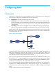
Configuring AAA Overview Authentication, Authorization, and Accounting (AAA) provides a uniform framework for implementing network access management. It specifies the following security functions: • Authentication—Identifies users and verifies their validity. • Authorization—Grants different users different rights and controls their access to resources and services.
RADIUS Remote Authentication Dial-In User Service (RADIUS) is a distributed information interaction protocol that uses a client/server model. It can protect networks against unauthorized access and is often used in network environments that require both high security and remote user access. The RADIUS authorization process is combined with the RADIUS authentication process, and user authorization information is piggybacked in authentication responses.
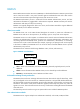
Basic RADIUS packet exchange process Figure 3 illustrates the interactions between a user host, the RADIUS client, and the RADIUS server. Figure 3 Basic RADIUS packet exchange process RADIUS uses in the following workflow: 1. The host sends a connection request that includes the user's username and password to the RADIUS client. 2. The RADIUS client sends an authentication request (Access-Request) to the RADIUS server.
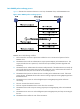
RADIUS packet format RADIUS uses UDP to transmit packets. To ensure smooth packet exchange between the RADIUS server and the client, RADIUS uses a series of mechanisms, including the timer mechanism, the retransmission mechanism, and the backup server mechanism. Figure 4 shows the RADIUS packet format. Figure 4 RADIUS packet format Descriptions of the fields are as follows: • The Code field (1 byte long) indicates the type of the RADIUS packet. Table 1 gives the main values and their meanings.
• The Authenticator field (16 bytes long) is used to authenticate responses from the RADIUS server and to encrypt user passwords. There are two types of authenticators: request authenticator and response authenticator. • The Attributes field (variable in length) includes specific authentication, authorization, and accounting information. This field can contain multiple attributes, each with three sub-fields: { Type—Type of the attribute.
No. Attribute No.
Figure 5 Format of attribute 26 HWTACACS HW Terminal Access Controller Access Control System (HWTACACS) is an enhanced security protocol based on TACACS (RFC 1492). HWTACACS is similar to RADIUS, and uses a client/server model for information exchange between the NAS and the HWTACACS server. HWTACACS typically provides AAA services for PPP, VPDN, and terminal users. In a typical HWTACACS scenario, terminal users need to log in to the NAS.
Figure 6 Basic HWTACACS packet exchange process for a Telnet user Host HWTACACS client HWTACACS server 1) The user tries to log in 2) Start-authentication packet 3) Authentication response requesting the username 4) Request for username 5) The user enters the username 6) Continue-authentication packet with the username 7) Authentication response requesting the password 8) Request for password 9) The user enters the password 10) Continue-authentication packet with the password 11) Response indicating succ
9. The user enters the password. 10. After receiving the login password, the HWTACACS client sends the HWTACACS server a continue-authentication packet that includes the login password. 11. If the authentication succeeds, the HWTACACS server sends back an authentication response to indicate that the user has passed authentication. 12. The HWTACACS client sends a user authorization request packet to the HWTACACS server. 13.
AAA methods AAA supports configuring different authentication, authorization, and accounting methods for different types of users in an ISP domain. The NAS determines the ISP domain and access type of a user, and uses the methods configured for the access type in the domain to control the user's access. AAA also supports configuring a set of default methods for an ISP domain. These default methods are used for users for whom no specific AAA methods are configured.
authorization is enabled, command accounting enables the accounting server to record all authorized commands. For more information about command accounting, see Fundamentals Configuration Guide. User role authentication—Authenticates each user who wants to obtain a temporary user role without logging out or getting disconnected. For more information about temporary user role authorization, see Fundamentals Configuration Guide.
No. Attribute Description 2 User-Password User password for PAP authentication, only present in Access-Request packets when PAP authentication is used. 3 CHAP-Password Digest of the user password for CHAP authentication, only present in Access-Request packets when CHAP authentication is used. 4 NAS-IP-Address IP address for the server to use to identify the client. Typically, a client is identified by the IP address of its access interface.
No. Attribute Description 60 CHAP-Challenge CHAP challenge generated by the NAS for MD5 calculation during CHAP authentication. Type of the physical port of the NAS that is authenticating the user. Possible values include: 61 NAS-Port-Type • • • • • • 15—Ethernet. 16—Any type of ADSL. 17—Cable. (With cable for cable TV.) 19—WLAN-IEEE 802.11. 201—VLAN. 202—ATM. If the port is an ATM or Ethernet one and VLANs are implemented on it, the value of this attribute is 201.
No. Sub-attribute Description 25 Result_Code Result of the Trigger-Request or SetPolicy operation, zero for success and any other value for failure. 26 Connect_ID Index of the user connection. 28 Ftp_Directory FTP user working directory. When the RADIUS client acts as the FTP server, this attribute is used to set the FTP directory for an FTP user on the RADIUS client. 29 Exec_Privilege EXEC user priority.
2. Configure AAA methods for the users' ISP domains. Remote AAA methods need to reference the configured RADIUS and HWTACACS schemes. Figure 9 AAA configuration procedure To configure AAA, perform the following tasks: Tasks at a glance (Required.) Perform at least one of the following tasks to configure local users or AAA schemes: • Configuring local users • Configuring RADIUS schemes • Configuring HWTACACS schemes (Required.) Configure AAA methods for ISP domains: (Required.) Creating an ISP domain 1.
Configuring local users To implement local authentication, authorization, and accounting, create local users and configure user attributes on the device. The local users and attributes are stored in the local user database on the device. A local user is uniquely identified by the combination of a username and a user type. The device only supports device management users who log in to the device for device management.
Configuring local user attributes Follow these guidelines when you configure local user attributes: • When you use the password-control enable command to globally enable the password control feature, local user passwords are not displayed. • The authentication mode of user interfaces is set by the authentication-mode command in user line view and affects access to commands for login users. In AAA (scheme) mode, the authorized user role determines the commands available for each login user.
Step Command Remarks The following default settings apply: • No authorization ACL, idle timeout period, or authorized VLAN is configured for local users. • FTP, SFTP, or SCP users are 7. (Optional.) Configure authorization attributes for the local user. authorization-attribute { acl acl-number | idle-cut minute | user-role role-name | vlan vlan-id | work-directory directory-name } * authorized access to the root directory of the device, but they do not have the access permission.
implement centralized user attributes management for the local users in the group. Local user attributes that are manageable include authorization attributes. By default, every new local user belongs to the default user group system and has all attributes of the group. To assign a local user to a different user group, use the group command in local user view. To configure user group attributes: Step Command Remarks system-view N/A 1. Enter system view. 2. Create a user group and enter its view.
Configuring RADIUS schemes A RADIUS scheme specifies the RADIUS servers that the device can work with and defines a set of parameters that the device uses to exchange information with the RADIUS servers, including the IP addresses of the servers, UDP port numbers, shared keys, and server types. Configuration task list Tasks at a glance (Required.) Creating a RADIUS scheme (Required.) Specifying the RADIUS authentication servers (Optional.
To specify RADIUS authentication servers for a RADIUS scheme: Step Command Remarks 1. Enter system view. system-view N/A 2. Enter RADIUS scheme view. radius scheme radius-scheme-name N/A • Specify the primary RADIUS 3. Specify RADIUS authentication servers.
Step Command Remarks • Specify the primary RADIUS 3. 4. accounting server: primary accounting { ipv4-address | ipv6 ipv6-address } [ port-number | key { cipher | simple } string | vpn-instance vpn-instance-name ] * Configure at least one command. By default, no accounting server is specified. Specify RADIUS accounting servers. • Specify a secondary RADIUS Two accounting servers in a scheme, primary or secondary, cannot have the same combination of IP address, port number, and VPN. (Optional.
Step 3. Specify a VPN for the RADIUS scheme. Command Remarks vpn-instance vpn-instance-name By default, a RADIUS scheme belongs to the public network. Setting the username format and traffic statistics units A username is typically in the format userid@isp-name, where isp-name represents the user's ISP domain name. By default, the ISP domain name is included in a username. However, older RADIUS servers might not recognize usernames that contain the ISP domain names.
Setting the status of RADIUS servers To control the RADIUS servers with which the device communicates when the current servers are no longer available, set the status of RADIUS servers to blocked or active. You can specify one primary RADIUS server and multiple secondary RADIUS servers, with the secondary servers functioning as the backup of the primary servers.
Step Command Remarks • Set the status of the primary RADIUS authentication server: state primary authentication { active | block } • Set the status of the primary RADIUS accounting server: state primary accounting { active | block } • Set the status of a secondary RADIUS Set the RADIUS server status. 3.
Step Command Remarks 1. Enter system view. system-view N/A 2. Enter RADIUS scheme view. radius scheme radius-scheme-name N/A nas-ip { ipv4-address | ipv6 ipv6-address } By default, the source IP address specified by the radius nas-ip command in system view is used. If the source IP address is not specified, the IP address of the outbound interface is used. 3. Specify a source IP address for outgoing RADIUS packets.
Step Command Remarks 1. Enter system view. system-view N/A 2. Enter RADIUS scheme view. radius scheme radius-scheme-name N/A 3. Set the RADIUS server response timeout timer. timer response-timeout seconds The default setting is 3 seconds. 4. Set the quiet timer for the servers. timer quiet minutes The default setting is 5 minutes. 5. Set the real-time accounting timer. timer realtime-accounting minutes The default setting is 12 minutes.
Enabling SNMP notifications for RADIUS When SNMP notifications are enabled for RADIUS, the SNMP agent supports the following notifications generated by RADIUS: • RADIUS server unreachable notification—The RADIUS server cannot be reached. RADIUS generates this notification if it cannot receive any response to an accounting or authentication request within the specified RADIUS request transmission attempts. • RADIUS server reachable notification—The RADIUS server can be reached.
Tasks at a glance (Optional.) Setting the username format and traffic statistics units (Optional.) Specifying the source IP address for outgoing HWTACACS packets (Optional.) Setting HWTACACS timers (Optional.) Displaying and maintaining HWTACACS Creating an HWTACACS scheme Create an HWTACACS scheme before performing any other HWTACACS configurations. You can configure up to 16 HWTACACS schemes. An HWTACACS scheme can be referenced by multiple ISP domains.
Specifying the HWTACACS authorization servers You can specify one primary authorization server and up to 16 secondary authorization servers for an HWTACACS scheme. When the primary server is not available, the device tries to communicate with the secondary servers in the order they are configured, and communicates with the first secondary server in active state. If redundancy is not required, specify only the primary server.
Step Command Remarks • Specify the primary HWTACACS 3. Specify HWTACACS accounting servers.
Setting the username format and traffic statistics units A username is typically in the format userid@isp-name, where isp-name represents the user's ISP domain name. By default, the ISP domain name is included in a username. However, if HWTACACS servers do not recognize usernames that contain ISP domain names, you can configure the device to remove the domain name from each username to be sent.
Step Command Remarks 1. Enter system view. system-view N/A 2. Specify a source IP address for outgoing HWTACACS packets. hwtacacs nas-ip { ipv4-address | ipv6 ipv6-address } [ vpn-instance vpn-instance-name ] By default, the IP address of the HWTACACS packet outbound interface is used as the source IP address. To specify a source IP address for a specific HWTACACS scheme: Step Command Remarks 1. Enter system view. system-view N/A 2. Enter HWTACACS scheme view.
If the quiet timer of a server expires, the status of the server changes back to active, but the device does not check the server again during the authentication or accounting process. If no server is found reachable during one search process, the device considers the authentication or accounting attempt a failure.
authorization, and local accounting. If you do not configure any AAA methods for an ISP domain, the device uses the system-defined AAA methods for users in the domain. Configuration prerequisites To use local authentication for users in an ISP domain, configure local user accounts on the device first. See "Configuring local user attributes.
Step Command Remarks 1. Enter system view. system-view N/A 2. Enter ISP domain view. domain isp-name N/A 3. Place the ISP domain in active or blocked state. state { active | block } By default, an ISP domain is in active state, and users in the domain can request network services. 4. Configure authorization attributes for authenticated users in the ISP domain.
Step Command Remarks By default, the default authentication method is used for login users. By default, the default authentication method is used for obtaining a temporary user role. 4. Specify the authentication method for login users. authentication login { hwtacacs-scheme hwtacacs-scheme-name [ radius-scheme radius-scheme-name ] [ local ] [ none ] | local [ none ] | none | radius-scheme radius-scheme-name [ hwtacacs-scheme hwtacacs-scheme-name ] [ local ] [ none ] } 5.
Step Specify the authorization method for login users. 5. Command Remarks authorization login { hwtacacs-scheme hwtacacs-scheme-name [ radius-scheme radius-scheme-name ] [ local ] [ none ] | local [ none ] | none | radius-scheme radius-scheme-name [ hwtacacs-scheme hwtacacs-scheme-name ] [ local ] [ none ] } By default, the default authorization method is used for login users.
Enabling the session-control feature A RADIUS server running on IMC can use session-control packets to inform disconnect or dynamic authorization change requests. This task enables the device to receive RADIUS session-control packets on UDP port 1812. To enable the session-control feature: Step Command Remarks 1. Enter system view. system-view N/A 2. Enable the session-control feature. radius session-control enable By default, the session-control feature is disabled.
Set the shared keys for secure HWTACACS communication to expert. Configure the switch to send usernames without domain names to the HWTACACS server. Configure the switch to assign the default user role network-operator to SSH users after they pass authentication. Figure 10 Network diagram Configuration procedure 1. Configure the HWTACACS server: # On the HWTACACS server, set the shared keys for secure communication with the switch to expert, add an account for the SSH user, and specify the password.
[Switch-isp-bbb] quit # Create local RSA and DSA key pairs. [Switch] public-key local create rsa [Switch] public-key local create dsa # Enable the SSH service. [Switch] ssh server enable # Enable scheme authentication for user lines VTY 0 through VTY 63. [Switch] line vty 0 63 [Switch-line-vty0-63] authentication-mode scheme [Switch-line-vty0-63] quit # Enable the default user role feature to assign authenticated SSH users the default user role network-operator.
Configuration procedure 1. Configure the HWTACACS server. (Details not shown.) 2. Configure the RADIUS server. (Details not shown.) 3. Configure the switch: # Assign IP addresses to interfaces. (Details not shown.) # Create local RSA and DSA key pairs. system-view [Switch] public-key local create rsa [Switch] public-key local create dsa # Enable the SSH service. [Switch] ssh server enable # Enable scheme authentication for user lines VTY 0 through VTY 63.
Verifying the configuration When the user initiates an SSH connection to the switch and enter the username hello@bbb and the correct password, the user successfully logs in and can use the commands for the network-operator user role. Authentication and authorization for SSH users by a RADIUS server Network requirements As shown in Figure 12, the RADIUS authentication and authorization server runs on IMC.
b. Set the ports for authentication and accounting to 1812 and 1813, respectively. c. Select the service type Device Management Service. d. Select the access device type HP. e. Select the access device from the device list or manually add the access device (with the IP address 10.1.1.2). f. Leave the default settings for other parameters and click OK.
Figure 14 Adding an account for device management 2. Configure the switch: # Assign an IP address to VLAN-interface 2, the SSH user access interface. system-view [Switch] interface vlan-interface 2 [Switch-Vlan-interface2] ip address 192.168.1.70 255.255.255.0 [Switch-Vlan-interface2] quit # Assign an IP address to VLAN-interface 3, through which the switch communicates with the server. [Switch] interface vlan-interface 3 [Switch-Vlan-interface3] ip address 10.1.1.2 255.255.255.
# Create a RADIUS scheme. [Switch] radius scheme rad # Specify the primary authentication server. [Switch-radius-rad] primary authentication 10.1.1.1 1812 # Set the shared key for secure communication with the server to expert in plain text. [Switch-radius-rad] key authentication simple expert # Include the domain names in usernames sent to the RADIUS server.
• The user is configured on the RADIUS server. • The correct password is entered. • The same shared key is configured on both the RADIUS server and the NAS. RADIUS packet delivery failure Symptom RADIUS packets cannot reach the RADIUS server. Analysis Possible reasons include: • A communication failure exists between the NAS and the RADIUS server. • The NAS is not configured with the IP address of the RADIUS server.
Troubleshooting HWTACACS Similar to RADIUS troubleshooting. See "Troubleshooting RADIUS.
Configuring password control Overview Password control refers to a set of functions provided by the device to manage login and super password setup, expirations, and updates for device management users, and to control user login status based on predefined policies. Local users are divided into two types: device management users and network access users. This feature applies only to device management users. For more information about local users, see "Configuring AAA.
configures a password, the system checks the complexity of the password. If the password is complexity-incompliant, the configuration will fail. You can apply the following password complexity requirements: • A password cannot contain the username or the reverse of the username. For example, if the username is abc, a password such as abc982 or 2cba is not complex enough. • A character or number cannot be repeated three or more times consecutively. For example, password a111 is not complex enough.
the history records by at least four characters and the four characters must be different from one another. Otherwise, the system will display an error message, and the password will not be changed. You can set the maximum number of history password records for the system to maintain for each user. When the number of history password records exceeds your setting, the most recent record overwrites the earliest one.
Password control configuration task list The password control functions can be configured in several different views, and different views support different functions. The settings configured in different views or for different objects have the following application ranges: • Settings for super passwords apply to only super passwords. • Settings in local user view apply to only the password of the local user.
Setting global password control parameters The password expiration time, minimum password length, and password composition policy can be configured in system view, user group view, or local user view. The password settings with a smaller application scope have higher priority. Global settings in system view apply to the passwords of the local users in all user groups if you do not configure password policies for these users in both local user view and user group view.
Setting user group password control parameters Step Command Remarks system-view N/A 1. Enter system view. 2. Create a user group and enter user group view. 3. Configure the password expiration time for the user group. password-control aging aging-time By default, the password expiration time of the user group equals the global password expiration time. Configure the minimum password length for the user group.
Step 3. 4. 5. Configure the password expiration time for the local user. Configure the minimum password length for the local user. Configure the password composition policy for the local user. 6. Configure the password complexity checking policy for the local user. 7. Specify the maximum number of login attempts and the action to be taken for the local user when the user fails to log in after the specified number of attempts.
Step Configure the password composition policy for super passwords. 4. Command Remarks password-control super composition type-number type-number [ type-length type-length ] By default, a super password must contain at least one character type and at least one character for each type. Displaying and maintaining password control Execute display commands in any view and reset commands in user view. Task Command Display password control configuration.
• A super password must contain four character types and at least five characters for each type. Configure a password control policy for the local Telnet user test to meet the following requirements: • The password must contain at least 24 characters. • The password must contain four character types and at least five characters for each type. • The password for the local user expires after 20 days. Configuration procedure # Enable the password control feature globally.
[Sysname-luser-manage-test] service-type telnet # Set the minimum password length to 24 for the local user. [Sysname-luser-manage-test] password-control length 24 # Specify that the password of the local user must contain at least four character types and at least five characters for each type. [Sysname-luser-manage-test] password-control composition type-number 4 type-length 5 # Set the password for the local user to expire after 20 days.
User group: system Bind attributes: Authorization attributes: Work directory: flash: User role list: network-operator Password control configurations: Password aging: Enabled (20 days) Password length: Enabled (24 characters) Password composition: Enabled (4 types, 5 characters per type) 59
Managing public keys Overview This chapter describes public key management for the asymmetric key algorithms including the Revest-Shamir-Adleman Algorithm (RSA), the Digital Signature Algorithm (DSA), and the Elliptic Curve Digital Signature Algorithm (ECDSA). Many security applications, including SSH, SSL, and PKI, use asymmetric key algorithms to secure communications between two parties, as shown in Figure 15.
• If you do not assign the key pair a name, the system assigns the default name to the key pair and marks the key pair as default. You can also assign the default name to another key pair, but the system does not mark the key pair as default. • The name of a key pair must be unique among all manually named key pairs that use the same key algorithm, but can be the same as a key pair that uses a different key algorithm.
• Exporting a host public key in a specific format to a file (use this method if you can import public keys from a file on the peer device) • Displaying a host public key in a specific format and saving it to a file (use this method if you can import public keys from a file on the peer device) • Displaying a host public key (use this method if you must manually enter the key on the peer device) Exporting a host public key in a specific format to a file Step 1. Command Enter system view.
NOTE: Do not distribute the RSA server public key serverkey (default) to a peer device. Destroying a local key pair To avoid key compromise, destroy a local key pair and generate a new pair after an intrusion event has occurred, the storage media of the device is replaced, the key pair has been used for a long time, or the local certificate has expired. For more information about the local certificate, see "Configuring PKI." To destroy a local key pair: Step Command Remarks 1. Enter system view.
Step Import a peer host public key from a public key file. 2. Command Remarks public-key peer keyname import sshkey filename By default, no peer host public key exists. Entering a peer public key Step Command Remarks 1. Enter system view. system-view N/A 2. Specify a name for the peer public key and enter public key view. public-key peer keyname By default, no peer host public key exists. 3. Type or copy the key.
Figure 16 Network diagram Device A Device B Configuration procedure 1. Configure Device A: # Create local RSA key pairs with default names on Device A, and use the default modulus length 1024 bits. system-view [DeviceA] public-key local create rsa The range of public key modulus is (512 ~ 2048). If the key modulus is greater than 512, it will take a few minutes. Press CTRL+C to abort. Input the modulus length [default = 1024]: Generating Keys... .................++++++ ........................
Enter public key view. Return to system view with "peer-public-key end" command.
# Create local RSA key pairs with default names on Device A, and use the default modulus length 1024 bits. system-view [DeviceA] public-key local create rsa The range of public key modulus is (512 ~ 2048). If the key modulus is greater than 512, it will take a few minutes. Press CTRL+C to abort. Input the modulus length [default = 1024]: Generating Keys... .................++++++ ......................................++++++ .....++++++++ ..............++++++++ Create the key pair successfully.
# Use FTP in binary mode to get the public key file devicea.pub from Device A. ftp 10.1.1.1 Connected to 10.1.1.1 (10.1.1.1). 220 FTP service ready. User(10.1.1.1:(none)):ftp 331 Password required for ftp. Password: 230 User logged in. Remote system type is UNIX. Using binary mode to transfer files. ftp> binary 200 TYPE is now 8-bit binary ftp> get devicea.pub 227 Entering Passive Mode (10,1,1,1,118,252) 150 Accepted data connection 226 File successfully transferred 301 bytes received in 0.
Configuring PKI Overview Public Key Infrastructure (PKI) is an asymmetric key infrastructure to encrypt and decrypt data for securing network services. Data encrypted with the public key can be decrypted only with the private key. Likewise, data encrypted with the private key can be decrypted only with the public key.
(CPS). You can obtain a CA policy through out-of-band means such as phone, disk, and email. Make sure you understand the CA policy before you select a trusted CA for certificate request because different CAs might use different policies. PKI architecture A PKI system consists of PKI entities, CAs, RAs and a certificate/CRL repository, as shown in Figure 18. Figure 18 PKI architecture • PKI entity—A PKI entity is an end user or host using PKI certificates.
2. The RA verifies the identity of the entity and sends a digital signature containing the identity information and the public key to the CA. 3. The CA verifies the digital signature, approves the request, and issues a certificate. 4. After receiving the certificate from the CA, the RA sends the certificate to the LDAP server or other certificate repositories to provide directory navigation services, and notifies the PKI entity that the certificate is successfully issued. 5.
PKI configuration task list Tasks at a glance (Required.) Configuring a PKI entity (Required.) Configuring a PKI domain (Required.) Requesting a certificate • Configuring automatic certificate request • Manually requesting a certificate (Optional.) Aborting a certificate request (Optional.) Obtaining certificates (Optional.) Verifying PKI certificates (Optional.) Specifying the storage path for the certificates and CRLs (Optional.) Exporting certificates (Optional.) Removing a certificate (Optional.
Step Command Remarks 3. Set a common name for the entity. common-name common-name-sting By default, the common name is not set. 4. Set the country code of the entity. country country-code-string By default, the country code is not set. 5. Set the locality of the entity. locality locality-name By default, the locality is not set. 6. Set the organization of the entity. organization org-name By default, the organization is not set. 7. Set the unit of the entity in the organization.
Step Command Remarks By default, no trusted CA is specified. To obtain a CA certificate, the trusted CA name must be provided. 3. Specify the trusted CA. ca identifier name The trusted CA name is in SCEP messages, and the CA server does not use this name unless the server has two CAs configured with the same registration server. 4. Specify the entity for certificate request. certificate request entity entity-name By default, no entity is specified. 5.
Step Command Remarks • Specify an RSA key pair: 10. Specify the key pair for certificate request. public-key rsa { { encryption name encryption-key-name [ length key-length ] | signature name signature-key-name [ length key-length ] } * | general name key-name [ length key-length ] } • Specify a DSA key pair: public-key dsa name key-name [ length key-length ] Use either command. By default, no key pair is specified.
Online mode—A certificate request can be automatically or manually submitted. The following sections describe the online request mode. • Configuring automatic certificate request IMPORTANT: If an automatically requested certificate will soon expire or has expired, the entity does not initiate a re-request to the CA automatically, and the applications using the certificate might be interrupted.
Before you manually submit a certificate request, make sure the CA certificate exists and a key pair is specified for the PKI domain: • The CA certificate is used to verify the authenticity and validity of the obtained local certificate. • The key pair is used for certificate request. Upon receiving the public key and the identity information, the CA signs and issues a certificate. After the CA issues the certificate, the device obtains and saves it locally.
To abort a certificate request: Step Command Remarks 1. Enter system view. system-view N/A 2. Abort a certificate request. pki abort-certificate-request domain domain-name This command is not saved in the configuration file. Obtaining certificates You can obtain the CA certificate, local certificates, and peer certificates related to a PKI domain from a CA and save them locally for higher lookup efficiency.
Configuration procedure To obtain certificates: Step 1. Enter system view. Command Remarks system-view N/A • Import certificates in offline mode: 2. Import or obtain certificates.
Step Command Remarks 7. (Optional.) Obtain the CRL and save it locally. pki retrieve-crl domain domain-name 8. Verify the validity of the certificates. pki validate-certificate domain domain-name { ca | local } The newly obtained CRL overwrites the old one, if any. The obtained CRL must be issued by a CA certificate in the CA certificate chain in the current domain. N/A Verifying certificates without CRL checking Step Command Remarks 1. Enter system view. system-view N/A 2.
Task Command Specify the storage path for the certificates and CRLs. Remarks pki storage { certificates | crls } dir-path By default, the storage path for the certificates and CRLs is the PKI directory on the storage media of the device. For a distributed device, you must specify a path on the current MPU rather than on other MPUs. Exporting certificates IMPORTANT: To export all certificates in the PKCS12 format, the PKI domain must have at least one local certificate.
2. Use public-key local destroy to destroy the existing local key pair. 3. Use public-key local create to generate a new key pair. 4. Request a new certificate. To remove a certificate: Step 1. 2. Command Remarks Enter system view. system-view N/A Remove a certificate. pki delete-certificate domain domain-name { ca | local | peer [ serial serial-num ] } If no serial number is specified, the command removes all peer certificates.
Step Command Remarks 4. Return to system view. quit N/A 5. Create a certificate access control policy and enter its view. pki certificate access-control-policy policy-name By default, no certificate access control policy exists. 6. Create a certificate access control rule (or statement). rule [ id ] { deny | permit } group-name By default, no statement is configured, and all certificates can pass the verification. You can create multiple statements for a certificate access control policy.
Figure 20 Network diagram Configuring the CA server 1. Create a CA server named myca: In this example, you must configure these basic attributes on the CA server: { { Nickname—Name of the trusted CA. Subject DN—DN attributes of the CA, including the common name (CN), organization unit (OU), organization (O), and country (C). You can use the default values for the other attributes. 2.
# Specify the RSA key pair with the purpose general, the name abc, and the length 1024 bits. [Device-pki-domain-torsa] public-key rsa general name abc length 1024 [Device-pki-domain-torsa] quit 4. Generate a local RSA key pair. [Device] public-key local create rsa name abc The range of public key size is (512 ~ 2048). If the key modulus is greater than 512,it will take a few minutes. Press CTRL+C to abort. Input the modulus length [default = 1024]: Generating Keys... ..........................++++++ .....
RSA Public Key: (1024 bit) Modulus (1024 bit): 00D67D50 41046F6A 43610335 CA6C4B11 F8F89138 E4E905BD 43953BA2 623A54C0 EA3CB6E0 B04649CE C9CDDD38 34015970 981E96D9 FF4F7B73 A5155649 E583AC61 D3A5C849 CBDE350D 2A1926B7 0AE5EF5E D1D8B08A DBF16205 7C2A4011 05F11094 73EB0549 A65D9E74 0F2953F2 D4F0042F 19103439 3D4F9359 88FB59F3 8D4B2F6C 2B Exponent: 65537 (0x10001) X509v3 extensions: X509v3 CRL Distribution Points: URI:http://4.4.4.133:447/myca.
2. Install the SCEP add-on: The Windows 2003 server does not support SCEP by default. Install the SCEP add-on on the server so that the device can automatically register and obtain its certificate from the server. After the SCEP add-on installation completes, you will see a URL. Use the URL to configure it on the device as the URL of the registration server for certificate request. 3. Modify the certificate service attributes: a.
[Device-pki-domain-winserver] quit 4. Generate an RSA local key pair: [Device] public-key local create rsa name abc The range of public key size is (512 ~ 2048). If the key modulus is greater than 512,it will take a few minutes. Press CTRL+C to abort. Input the modulus length [default = 1024]: Generating Keys... ..........................++++++ .....................................++++++ Create the key pair successfully. 5. Request a local certificate: # Obtain the CA certificate and save it locally.
10242FDD D3947F5E 2DA70BD9 1FAF07E5 1D167CE1 FC20394F 476F5C08 C5067DF9 CB4D05E6 55DC11B6 9F4C014D EA600306 81D403CF 2D93BC5A 8AF3224D 1125E439 78ECEFE1 7FA9AE7B 877B50B8 3280509F 6B Exponent: 65537 (0x10001) X509v3 extensions: X509v3 Subject Key Identifier: B68E4107 91D7C44C 7ABCE3BA 9BF385F8 A448F4E1 X509v3 Authority Key Identifier: keyid:9D823258 EADFEFA2 4A663E75 F416B6F6 D41EE4FE X509v3 CRL Distribution Points: URI:http://l00192b/CertEnroll/CA%20server.crl URI:file://\\l00192b\CertEnroll\CA server.
Configuring the device 1. Synchronize the system time of the device with the CA server, so that the device can correctly request a certificate. 2. Create an entity named aaa with the common name as rnd, the country code as CN, the organization name as test, and the unit name as software.
[Device] pki request-certificate domain openca Start to request the general certificate ... … Request certificate of domain openca successfully Verifying the configuration # After obtaining the local certificate, display information about the certificate.
keyid:85:EB:D5:F7:C9:97:2F:4B:7A:6D:DD:1B:4D:DD:00:EE:53:CF:FD:5B X509v3 Issuer Alternative Name: DNS:root@docm.com, DNS:, IP Address:192.168.154.145, IP Address:192.168.154.138 Authority Information Access: CA Issuers - URI:http://192.168.222.218/pki/pub/cacert/cacert.crt OCSP - URI:http://192.168.222.218:2560/ 1.3.6.1.5.5.7.48.12 - URI:http://192.168.222.218:830/ X509v3 CRL Distribution Points: Full Name: URI:http://192.168.222.218/pki/pub/crl/cacrl.
Figure 23 Network diagram Configuration procedure 1. Export the certificate on Device A to specified files: # Export the CA certificate to a file named pkicachain.pem in PEM format. system-view [DeviceA] pki export domain exportdomain pem ca filename pkicachain.pem # Export the local certificate to a file named pkilocal.pem in PEM format, and use 3DES_CBC to encrypt the private key with the password 111111. [DeviceA] pki export domain exportdomain pem local 3des-cbc 111111 filename pkilocal.
friendlyName: localKeyID: D5 DF 29 28 C8 B9 D9 49 6C B5 44 4B C2 BC 66 75 FE D6 6C C8 subject=/C=CN/O=OpenCA Labs/OU=Users/CN=subencr 11 issuer=/C=CN/L=shangdi/ST=beijing/O=OpenCA Labs/OU=docm/CN=subca1 -----BEGIN CERTIFICATE----MIIEUDCCAzigAwIBAgIKCHxnAVyzWhIPLzANBgkqhkiG9w0BAQsFADBmMQswCQYD … -----END CERTIFICATE----Bag Attributes friendlyName: localKeyID: D5 DF 29 28 C8 B9 D9 49 6C B5 44 4B C2 BC 66 75 FE D6 6C C8 Key Attributes: -----BEGIN ENCRYPTED PRIVATE KEY----MIICxjBABgkqhkiG9w0BBQ0
98:2c:79:ba:5e:8d:97:39:53:00 Signature Algorithm: sha256WithRSAEncryption Issuer: C=CN, L=shangdi, ST=beijing, O=OpenCA Labs, OU=docm, CN=subca1 Validity Not Before: May 26 05:56:49 2011 GMT Not After : Nov 22 05:56:49 2012 GMT Subject: C=CN, O=OpenCA Labs, OU=Users, CN=subsign 11 Subject Public Key Info: Public Key Algorithm: rsaEncryption Public-Key: (1024 bit) Modulus: 00:9f:6e:2f:f6:cb:3d:08:19:9a:4a:ac:b4:ac:63: ce:8d:6a:4c:3a:30:19:3c:14:ff:a9:50:04:f5:00: ee:a3:aa:03:cb:b3:49:c4:f8:ae:55:ee:43:93:69
Full Name: URI:http://192.168.40.130/pki/pub/crl/cacrl.
Netscape Cert Type: SSL Server X509v3 Key Usage: Key Encipherment, Data Encipherment Netscape Comment: VPN Server of OpenCA Labs X509v3 Subject Key Identifier: CC:96:03:2F:FC:74:74:45:61:38:1F:48:C0:E8:AA:18:24:F0:2B:AB X509v3 Authority Key Identifier: keyid:70:54:40:61:71:31:02:06:8C:62:11:0A:CC:A5:DB:0E:7E:74:DE:DD X509v3 Subject Alternative Name: email:subencr@docm.com X509v3 Issuer Alternative Name: DNS:subca1@docm.com, DNS:, IP Address:1.1.2.2, IP Address:2.2.1.
Failed to obtain the CA certificate Symptom The CA certificate cannot be obtained. Analysis • The network connection is down because, for example, the network cable is damaged or the connectors have bad contact. • No trusted CA is specified. • The URL of the registration server is not correct or not specified. • The system time of the device is not synchronized with the CA server. • The source IP address of the PKI protocol packets is not specified or not correct.
3. Configure the correct LDAP server. 4. Specify the key pair used for certificate request in the PKI domain, generate the proper key pair, and make sure it matches the local certificates to the obtained. 5. Reference the proper PKI entity in the PKI domain, and correctly configure the PKI entity. 6. Obtain CRLs. 7. Specify the correct source IP address for PKI protocol packets that the CA server can accept. For the correct settings, contact the CA server administrator. 8.
Failed to obtain CRLs Symptom CRLs cannot be obtained. Analysis • The network connection is down because, for example, the network cable is damaged or the connectors have bad contact. • No CA certificate has been obtained before you try to obtain CRLs. • The URL of the CRL repository is not configured, and the proper URL cannot be obtained from the CA certificate or local certificates in the PKI domain. • The specified URL of the CRL repository is incorrect.
Failed to import a local certificate Symptom A local certificate cannot be imported. Analysis • The PKI domain has no CA certificate, and the certificate file to be imported does not contain the CA certificate chain. • CRL checking is enabled, but CRLs do not exist locally or CRLs cannot be obtained. • The specified format does not match the actual format of the imported file. • The device and the certificate do not have the local key pair. • The certificate has been revoked.
Failed to set the storage path Symptom The storage path for certificates or CRLs cannot be set. Analysis • The specified storage path does not exist. • The specified storage path is illegal. • The disk space is full. 1. Use mkdir to create the path. 2. Specify the correct storage path for certificates or CRLs. 3. Clear up the disk space of the device.
Configuring SSH Overview Secure Shell (SSH) is a network security protocol. Using encryption and authentication, SSH can implement secure remote access and file transfer over an insecure network. Adopting the typical client/server model, SSH can establish a channel to protect data transfer based on TCP. SSH includes two versions: SSH1.x and SSH2.0 (hereinafter referred to as SSH1 and SSH2), which are not compatible. SSH2 is better than SSH1 in performance and security.
Stages Description Key exchange The two parties use the DH exchange algorithm to dynamically generate the session key for protecting data transfer and the session ID for identifying the SSH connection. In this stage, the client authenticates the server as well. Authentication The SSH server authenticates the client in response to the client's authentication request.
• Password-publickey authentication—The server requires SSH2 clients to pass both password authentication and publickey authentication. However, an SSH1 client only needs to pass either authentication, regardless of the requirement of the server. • Any authentication—The server requires clients to pass either password authentication or publickey authentication. Configuring the device as an SSH server You can configure the device as an Stelnet, SFTP, or SCP server.
Configuration guidelines • SSH supports locally generated DSA and RSA key pairs with default names rather than with specified names. For more information about the commands that are used to generate keys, see Security Command Reference. • The public-key local create rsa command generates a server key pair and a host key pair for RSA. SSH1 uses the public key in the server key pair of the SSH server to encrypt the session key before transmitting the session key.
Configuring the user lines for Stelnet clients Dependent on different SSH applications, an SSH client can be an Stelnet, SFTP, or SCP client. The Stelnet client accesses the device through a VTY user line. You must configure the user lines for SSH clients to allow SSH login. The configuration takes effect only on the clients at next login. The SFTP or SCP client accesses the device without using a VTY user line. To configure the user lines for Stelnet clients: Step Command Remarks 1. Enter system view.
Step Command Remarks 1. Enter system view. system-view N/A 2. Enter public key view. public-key peer keyname N/A Configure a client's host public key. 3. Enter the content of the host public key When you enter the contents for a host public key, you can use spaces and carriage returns between characters. When you save the host public key, spaces and carriage returns are removed automatically. For more information, see "Managing public keys." Return to system view. 4.
{ { If the authentication method is password, the user role is authorized by the remote AAA server or the local device. If the authentication method is publickey or password-publickey, the user role is specified by the authorization-attribute command in the associated local user view. • If you change the authentication method or public key for an SSH user that has been logged in, the change can take effect only on the user at next login.
Maximum number of concurrent online SSH users. When the number of online SSH users reaches the upper limit, the system refuses new SSH connection requests. • To set the SSH management parameters: Step Command Remarks 1. Enter system view. system-view N/A 2. Enable the SSH server to support SSH1 clients. ssh server compatible-ssh1x enable By default, the SSH server supports SSH1 clients. 3. Set the RSA server key pair update interval.
Specifying a source IP address or source interface for the Stelnet client By default, an Stelnet client uses the IP address of the outbound interface specified by the route to the Stelnet server when communicating with the Stelnet server. You can specify a source IP address or source interface for the client to communicate with the server.
Task Command Remarks • Establish a connection to an IPv4 Stelnet server: Establish a connection to an Stelnet server.
communicate with each other, and to improve the manageability of SFTP clients in the authentication service, HP recommends that you specify a loopback interface as the source interface. To specify a source IP address or source interface for the SFTP client: Step 1. Enter system view. Command Remarks system-view N/A • Specify a source IPv4 address or 2. Specify a source address or interface for the SFTP client.
Task Command Remarks • Establish a connection to an IPv4 SFTP server: Establish a connection to an SFTP server.
Working with SFTP files Task Command Remarks Change the name of a file on the SFTP server. rename old-name new-name Available in SFTP client view. Download a file from the remote server and save it locally. get remote-file [ local-file ] Available in SFTP client view. Upload a local file to the SFTP server. put local-file [ remote-file ] Available in SFTP client view. Display the files under a directory.
When an SCP client accesses an SCP server, it uses the locally saved host public key of the server to authenticate the server. When acting as an SCP client, the device supports the first authentication by default. When the device accesses an SCP server for the first time but it is not configured with the host public key of the SCP server, it can access the server and locally save the server's host public key for future use.
Task Command Display SSH user information on the SSH server. display ssh user-information [ username ] Display the public keys of the local key pairs. display public-key local { dsa | rsa } public [ name publickey-name ] Display the public keys of the SSH peers.
Input the modulus length [default = 1024]: Generating Keys... .++++++++++++++++++++++++++++++++++++++++++++++++++* ........+......+.....+......................................+ ...+.................+..........+...+. Create the key pair successfully. # Enable the SSH server function. [Switch] ssh server enable # Assign an IP address to VLAN-interface 2. The Stelnet client uses this IP address as the destination for SSH connection. [Switch] interface vlan-interface 2 [Switch-Vlan-interface2] ip address 192.
Figure 25 Specifying the host name (or IP address) c. Click Open to connect to the server. If the connection is successfully established, the system asks you to enter the username and password. After entering the username (client001 in this example) and password (aabbcc in this example), you can enter the CLI of the server.
Configuration procedure In the server configuration, the client's host public key is required. Use the client software to generate RSA key pairs on the client before configuring the Stelnet server. There are different types of Stelnet client software, such as PuTTY, and OpenSSH. This example uses an Stelnet client that runs PuTTY version 0.58. The configuration procedure is as follows: 1. Generate the RSA key pairs on the Stelnet client: a. Run PuTTYGen.
Figure 28 Generating process c. After the key pair is generated, click Save public key, enter a file name (key.pub in this example), and click Save.
d. Click Save private key to save the private key. A confirmation dialog box appears. e. Click Yes, enter a file name (private.ppk in this example), and click Save. f. Transmit the public key file to the server through FTP or TFTP. (Details not shown.) 2. Configure the Stelnet server: # Generate the RSA key pairs. system-view [Switch] public-key local create rsa The range of public key size is (512 ~ 2048). If the key modulus is greater than 512, it will take a few minutes. Press CTRL+C to abort.
# Create a local device management user client002 with the service type ssh and the user role network-admin. [Switch] local-user client002 class manage [Switch-luser-manage-client002] service-type ssh [Switch-luser-manage-client002] authorization-attribute user-role network-admin [Switch-luser-manage-client002] quit 3. Specify the private key file and establish a connection to the Stelnet server: a. Launch PuTTY.exe on the Stelnet client to enter the interface shown in Figure 30. b.
Figure 31 Specifying the preferred SSH version e. Select Connection > SSH > Auth from the navigation tree. The window shown in Figure 32 appears. f. Click Browse… to bring up the file selection window, navigate to the private key file (private.ppk in this example), and click OK.
Figure 32 Specifying the private key file g. Click Open to connect to the server. If the connection is successfully established, the system asks you to enter the username. After entering the username (client002), you can enter the CLI of the server.
[SwitchB] public-key local create rsa The range of public key size is (512 ~ 2048). If the key modulus is greater than 512, it will take a few minutes. Press CTRL+C to abort. Input the modulus length [default = 1024]: Generating Keys... ........................++++++ ...................++++++ ..++++++++ ............++++++++ Create the key pair successfully. # Generate a DSA key pair. [SwitchB] public-key local create dsa The range of public key size is (512 ~ 2048).
[SwitchA-Vlan-interface2] ip address 192.168.1.56 255.255.255.0 [SwitchA-Vlan-interface2] quit [SwitchA] quit You can determine whether to configure the host public key of the server on the client before establishing a connection to the server: { If you do not configure the host public key of the server on the client, select Yes to access the server without authenticating the server, and locally save the host public key of the server. ssh2 192.168.1.
[SwitchA-pkey-public-key-key1]D716D7DB9FCABB4ADBF6FB4FDB0CA25C761B308EF53009F7 1 01F7C62621216D5A572C379A32AC290 [SwitchA-pkey-public-key-key1]E55B394A217DA38B65B77F0185C8DB8095522D1EF044B465 E 8716261214A5A3B493E866991113B2D [SwitchA-pkey-public-key-key1]485348 [SwitchA-pkey-public-key-key1] peer-public-key end [SwitchA] quit # Establish an SSH connection to the server 192.168.1.40 and specify the host public key of the server. ssh2 192.168.1.40 publickey key1 Username: client001 client001@192.
.++++++++++++++++++++++++++++++++++++++++++++++++++* ........+......+.....+......................................+ ...+.................+..........+...+ Create the key pair successfully. # Export the DSA host public key to file key.pub. [SwitchA] public-key local export dsa ssh2 key.pub [SwitchA] quit # Transmit the public key file key.pub to the server through FTP or TFTP. (Details not shown.) 2. Configure the Stelnet server: # Generate the RSA key pairs.
# Create an SSH user client002 with the authentication method publickey, and assign the public key switchkey to the user. [SwitchB] ssh user client002 service-type stelnet authentication-type publickey assign publickey switchkey # Create a local device management user client002 with the service type ssh and the user role network-admin.
........................++++++ ...................++++++ ..++++++++ ............++++++++ Create the key pair successfully. # Generate a DSA key pair. [Switch] public-key local create dsa The range of public key size is (512 ~ 2048). If the key modulus is greater than 512, it will take a few minutes. Press CTRL+C to abort. Input the modulus length [default = 1024]: Generating Keys... .++++++++++++++++++++++++++++++++++++++++++++++++++* ........+......+.....+......................................+ ...+......
Figure 36 SFTP client interface Publickey authentication enabled SFTP client configuration example Network requirements As shown in Figure 37, you can log in to Switch B through the SFTP client that runs on Switch A and are assigned the user role network-admin to execute file management and transfer operations. Switch B acts as the SFTP server and uses publickey authentication and the RSA public key algorithm.
The range of public key size is (512 ~ 2048). If the key modulus is greater than 512, it will take a few minutes. Press CTRL+C to abort. Input the modulus length [default = 1024]: Generating Keys... ........................++++++ ...................++++++ ..++++++++ ............++++++++ Create the key pair successfully. # Export the host public key to the file pubkey. [SwitchA] public-key local export rsa ssh2 pubkey [SwitchA] quit # Transmit the public key file pubkey to the server through FTP or TFTP.
[SwitchB] public-key peer switchkey import sshkey pubkey # Create an SSH user client001 with the service type sftp, authentication method publickey, and public key switchkey. [SwitchB] ssh user client001 service-type sftp authentication-type publickey assign publickey switchkey # Create a local device management user client001 with the service type ssh, the user role network-admin, and the working directory flash:/.
# Rename directory new1 to new2 and verify that the directory has been successfully renamed . sftp> rename new1 new2 sftp> dir -l -rwxrwxrwx 1 noone nogroup 1759 Aug 23 06:52 config.
Configuration procedure 1. Configure the SCP server: # Generate the RSA key pairs. system-view [SwitchB] public-key local create rsa The range of public key size is (512 ~ 2048). If the key modulus is greater than 512, it will take a few minutes. Press CTRL+C to abort. Input the modulus length [default = 1024]: Generating Keys... ........................++++++ ...................++++++ ..++++++++ ............++++++++ Create the key pair successfully. # Generate a DSA key pair.
[SwitchA-Vlan-interface2] quit [SwitchA] quit 3. Connect to the SCP server, download the file remote.bin from the server, and save it locally with the name local.bin. scp 192.168.0.1 get remote.bin local.bin Username: client001 Connected to 192.168.0.1 ... The Server is not authenticated. Continue? [Y/N]:y Do you want to save the server public key? [Y/N]:n Enter password: 18471 bytes transfered in 0.001 seconds.
Configuring SSL Overview Secure Sockets Layer (SSL) is a cryptographic protocol that provides communication security for TCP-based application layer protocols. SSL has been widely used in applications such as e-business and online banking to provide secure data transmission over the Internet.
Figure 40 SSL protocol stack The following describes the major functions of SSL protocols: • SSL record protocol—Fragments data received from the upper layer, computes and adds MAC to the data, and encrypts the data. • SSL handshake protocol—Negotiates the cipher suite used for secure communication (including the symmetric encryption algorithm, key exchange algorithm, and MAC algorithm), authenticates the server and client, and securely exchanges the key between the server and client.
Step Command Remarks By default, no PKI domain is specified for an SSL server policy. 3. (Optional.) Specify a PKI domain for the SSL server policy. pki-domain domain-name If SSL clients authenticate the server through a digital certificate, you must use this command to specify a PKI domain and request a local certificate for the SSL server through the PKI domain. For information about how to create and configure a PKI domain, see "Configuring PKI." 4.
Step Command Remarks By default, no PKI domain is specified for an SSL client policy. 3. (Optional.) Specify a PKI domain for the SSL client policy. pki-domain domain-name If the SSL server authenticates the SSL client through a digital certificate, you must use this command to specify a PKI domain and request a local certificate for the SSL client through the PKI domain. For information about how to create and configure a PKI domain, see "Configuring PKI." 4.
Configuring IP source guard Overview IP source guard prevents spoofing attacks by using an IP source guard binding table to match legitimate packets. It drops all packets that do not match the table. The IP source guard binding table can include the following binding entries: • IP-interface binding entries. • MAC-interface binding entries. • IP-MAC-interface binding entries. • IP-VLAN-interface binding entries. • MAC-VLAN-interface binding entries. • IP-MAC-VLAN-interface binding entries.
IP source guard use static IPv4 source guard binding entries on an interface to filter IPv4 packets received by the interface or cooperate with the ARP detection feature to check user validity. IP source guard use static IPv6 source guard binding entries on an interface to filter IPv6 packets received by the interface. For more information about ARP detection, see "Configuring ARP attack protection.
Tasks at a glance (Required.) Enabling IPv6 source guard on an interface (Optional.) Configuring a static IPv6 source guard binding entry Configuring the IPv4 source guard function You cannot configure the IPv4 source guard function on a service loopback interface. If IPv4 source guard is enabled on an interface, you cannot assign the interface to a service loopback group.
Configuring a static IPv4 source guard binding entry Static IPv4 source guard binding entries include global static IPv4 source entries and interface-specific static IPv4 source guard binding entries. A global static IPv4 source guard binding entry defines both the source IP address and source MAC address of packets that can be forwarded, and it takes effect on all interfaces. Static IPv4 source guard binding entries on an interface take priority over the global static IPv4 source guard binding entries.
Enabling IPv6 source guard on an interface You must first enable the IPv6 source guard function on an interface and use static entries to filter packets. All the fields in a static IPv6 source guard binding entry are used by IP source guard to filter packets. For more information about how to configure a static IPv6 source guard binding entry, see "Configuring a static IPv6 source guard binding entry." To enable the IPv6 source guard function on an interface: Step 1. 2. 3. Enter system view.
Step Enter interface view. 2. Command Remarks interface interface-type interface-number These types of interfaces are supported: Layer 2 Ethernet port, Layer 3 Ethernet interface, VLAN interface. By default, no static IPv6 source guard binding entry is configured on an interface. Configure a static IPv6 source guard binding entry. 3.
Figure 42 Network diagram Configuration procedure 1. Configure Switch A: # Configure IP addresses for the interfaces. (Details not shown.) # Enable IPv4 source guard on FortyGigE 1/0/2. system-view [SwitchA] interface fortygige 1/0/2 [SwitchA-FortyGigE1/0/2] ip verify source ip-address mac-address # On FortyGigE 1/0/2, configure a static IPv4 source guard binding entry for Host C. [SwitchA-FortyGigE1/0/2] ip source binding ip-address 192.168.0.
Verifying the configuration # Display static IPv4 source guard binding entries on Switch A. The output shows that the static IPv4 source guard binding entries are configured successfully. display ip source binding static Total entries found: 2 IP Address MAC Address 192.168.0.1 0001-0203-0405 FGE1/0/2 Interface VLAN Type N/A Static 192.168.0.3 0001-0203-0406 FGE1/0/1 N/A Static # Display static IPv4 source guard binding entries on Switch B.
# Configure FortyGigE 1/0/2 as a trusted interface. [Switch] interface fortygige 1/0/2 [Switch-FortyGigE1/0/2] dhcp snooping trust [Switch-FortyGigE1/0/2] quit 3. Enable IPv4 source guard on FortyGigE 1/0/1 to filter packets based on both the source IP address and the MAC address.
[Switch-Vlan-interface100] quit 2. Configure the DHCP relay agent: # Enable the DHCP service. [Switch] dhcp enable # Enable recording DHCP relay client entries. [Switch] dhcp relay client-information record # Configure VLAN-interface 100 to operate in DHCP relay mode. [Switch] interface vlan-interface 100 [Switch-Vlan-interface100] dhcp select relay # Specify the IP address of the DHCP server. [Switch-Vlan-interface100] dhcp relay server-address 10.1.1.
IPv6 Address MAC Address 2001::1 0001-0202-0202 FGE1/0/1 Interface 152 VLAN Type N/A Static
Configuring ARP attack protection ARP attacks and viruses are threatening LAN security. This chapter describes multiple features used to detect and prevent ARP attacks. Although ARP is easy to implement, it provides no security mechanism and is vulnerable to network attacks. An attacker can exploit ARP vulnerabilities to attack network devices in the following ways: • Acts as a trusted user or gateway to send ARP packets so the receiving devices obtain incorrect ARP entries.
• ARP source suppression—If the attack packets have the same source address, you can enable the ARP source suppression function, and set the maximum number of unresolvable IP packets that the device can receive from a host within 5 seconds. If the threshold is reached, the device stops resolving packets from the host until the 5 seconds elapse. • ARP blackhole routing—You can enable the ARP blackhole routing function regardless of whether the attack packets have the same source address.
Figure 46 Network diagram Configuration considerations If the attack packets have the same source address, configure the ARP source suppression function as follows: 1. Enable ARP source suppression. 2. Set the threshold to 100. If the number of unresolvable IP packets received from a host within 5 seconds exceeds 100, the device stops resolving packets from the host until the 5 seconds elapse.
Configuration guidelines Configure this feature when ARP detection is enabled, or when ARP flood attacks are detected. Configuration procedure This task sets a rate limit for ARP packets received on an interface. When the receiving rate of ARP packets on the interface exceeds the rate limit, those packets are discarded. You can enable sending notifications to the SNMP module or enable logging for ARP packet rate limit.
Configuring source MAC-based ARP attack detection This feature checks the number of ARP packets received from the same MAC address within 5 seconds against a specific threshold. If the threshold is exceeded, the device adds the MAC address in an ARP attack entry. Before the entry is aged out, the device handles the attack by using either of the following methods: • Monitor—Only generates log messages. • Filter—Generates log messages and filters out subsequent ARP packets from that MAC address.
Configuration example Network requirements As shown in Figure 47, the hosts access the Internet through a gateway (Device). If malicious users send a large number of ARP requests to the gateway, the gateway might crash and cannot process requests from the clients. To solve this problem, configure source MAC-based ARP attack detection on the gateway.
[Device] arp source-mac exclude-mac 0012-3f86-e94c Configuring ARP packet source MAC consistency check This feature enables a gateway to filter out ARP packets whose source MAC address in the Ethernet header is different from the sender MAC address in the message body, so that the gateway can learn correct ARP entries. To enable ARP packet source MAC address consistency check: Step Command Remarks 1. Enter system view. system-view N/A 2. Enable ARP packet source MAC address consistency check.
Configuring user validity check Upon receiving an ARP packet from an ARP untrusted interface, the device compares the sender IP and MAC addresses against the static IP source guard binding entries and the DHCP snooping entries. If a match is found from those entries, the ARP packet is considered valid and is forwarded. If no match is found, the ARP packet is considered invalid and is discarded. Static IP source guard binding entries are created by using the ip source binding command.
ip—Checks the sender and target IP addresses of ARP replies, and the sender IP address of ARP requests. All-one or multicast IP addresses are considered invalid and the corresponding packets are discarded. • To configure ARP packet validity check: Step Command Remarks 1. Enter system view. system-view N/A 2. Enter VLAN view. vlan vlan-id N/A 3. Enable ARP detection. arp detection enable By default, ARP detection is disabled. 4. Return to system view. quit N/A 5.
Task Command Display the VLANs enabled with ARP detection. display arp detection Display the ARP detection statistics. display arp detection statistics [ interface interface-type interface-number ] Clear the ARP detection statistics.
[SwitchB] interface fortygige 1/0/3 [SwitchB-FortyGigE1/0/3] dhcp snooping trust [SwitchB-FortyGigE1/0/3] quit # Enable ARP detection for VLAN 10. [SwitchB] vlan 10 [SwitchB-vlan10] arp detection enable # Configure the upstream interface as a trusted interface (an interface is an untrusted interface by default).
To delete a specific static ARP entry converted from a dynamic one, use the undo arp ip-address [ vpn-instance-name ] command. Use the reset arp all command to delete all ARP entries or the reset arp static command to delete all static ARP entries. • Configuration procedure To configure ARP automatic scanning and fixed ARP: Step Command 1. Enter system view. system-view 2. Enter Layer 3 Ethernet interface/VLAN interface/Layer 3 aggregate interface view. interface interface-type interface-number 3.
Step 3. Enable ARP gateway protection for the specified gateway. Command Remarks arp filter source ip-address By default, ARP gateway protection is disabled. Configuration example Network requirements As shown in Figure 49, Host B launches gateway spoofing attacks to Switch B. As a result, traffic that Switch B intends to send to Switch A is sent to Host B. Configure Switch B to block such attacks. Figure 49 Network diagram Configuration procedure # Configure ARP gateway protection on Switch B.
Configuration guidelines When you configure ARP filtering, follow these guidelines: • You can configure a maximum of eight permitted entries on an interface. • Do not configure both the arp filter source and arp filter binding commands on an interface. • If ARP filtering operates with ARP detection, ARP filtering applies first. Configuration procedure To configure ARP filtering: Step Command Remarks 1. Enter system view. system-view N/A 2.
Configuration procedure # Configure ARP filtering on Switch B. system-view [SwitchB] interface fortygige 1/0/1 [SwitchB-FortyGigE1/0/1] arp filter binding 10.1.1.2 000f-e349-1233 [SwitchB-FortyGigE1/0/1] quit [SwitchB] interface fortygige 1/0/2 [SwitchB-FortyGigE1/0/2] arp filter binding 10.1.1.3 000f-e349-1234 After the configuration is complete, FortyGigE 1/0/1 permits ARP packets from Host A, and discards other ARP packets.
Support and other resources Contacting HP For worldwide technical support information, see the HP support website: http://www.hp.
Conventions This section describes the conventions used in this documentation set. Command conventions Convention Description Boldface Bold text represents commands and keywords that you enter literally as shown. Italic Italic text represents arguments that you replace with actual values. [] Square brackets enclose syntax choices (keywords or arguments) that are optional. { x | y | ... } Braces enclose a set of required syntax choices separated by vertical bars, from which you select one.
Network topology icons Represents a generic network device, such as a router, switch, or firewall. Represents a routing-capable device, such as a router or Layer 3 switch. Represents a generic switch, such as a Layer 2 or Layer 3 switch, or a router that supports Layer 2 forwarding and other Layer 2 features. Represents an access controller, a unified wired-WLAN module, or the switching engine on a unified wired-WLAN switch. Represents an access point.
Index A RADIUS accounting-on feature configuration, 27 AAA RADIUS attributes, 11 RADIUS authentication server specification, 20 configuration, 1, 14 RADIUS implementation, 2 device implementation, 9 RADIUS max request transmission attempts, 23 displaying, 39 RADIUS scheme configuration, 20 displaying local users/local user groups, 19 RADIUS scheme creation, 20 HWTACACS accounting server specification, 30 RADIUS scheme VPN specification, 22 RADIUS security policy server IP address configuration,
security AAA RADIUS, 11 active security AAA RADIUS common standard attributes, 11 security ARP active acknowledgement, 159 Address Resolution Protocol.
security AAA SSH user local authentication+HWTACACS authorization+RADIUS accounting, 41 security PKI certificate verification (CRL checking), 79 security PKI certificate verification (without CRL checking), 80 auto security ARP automatic scanning, 163 client security PKI certificate request (automatic), 76 security SSL client policy configuration, 140 command B security AAA command accounting method, 10 blackhole routing (ARP), 154 C security AAA command authorization method, 10 communication secur
security ARP packet rate limit, 155 security SSH SCP file with password authentication, 135 security ARP packet source MAC consistency check, 159 security SSH SFTP, 130 security ARP packet validity check, 160 security SSH SFTP client publickey authentication, 132 security ARP restricted forwarding, 161 security SSH SFTP server password authentication, 130 security ARP source MAC-based attack detection, 157, 158 security SSH Stelnet, 117 security ARP source suppression, 154 security ARP unresolvabl
security password control configuration, 49, 52, 56 security local key pair, 63 security password control global parameters, 53 detecting security ARP detection configuration, 159 security password control local user parameters, 54 security ARP source MAC-based attack detection, 157, 158 security password control user group parameters, 54 device security password setting, 49 security AAA configuration, 1, 14 security SFTP server function enable, 106 security AAA device management user configurati
security SSH Stelnet client publickey authentication, 128 security PKI RSA Keon CA server certificate request, 83 security PKI verification (CRL checking), 79 dst-mac validity check (ARP), 160 security PKI verification (without CRL checking), 80 dynamic security IP source guard dynamic binding entry, 143 security PKI Windows 2003 CA server certificate request, 86 security IPv4 source guard dynamic configuration with DHCP relay, 150 directory security IPv4 source guard dynamic configuration with DHCP
security peer host public key import from file, 63 security SSH local DSA key pair, 105 security public key import from file, 66 security SSH local RSA key pair, 105 security SSH SCP file transfer with password authentication, 135 security SSH SFTP, 115 filtering security ARP packets, 165, 166 fixed ARP configuration, 163 format security AAA HWTACACS username, 32 security AAA RADIUS packet format, 4 security AAA RADIUS username, 23 forwarding IP source guard configuration, 147 H handshake protocol (SSL
IPv4. See IPv4 source guard IMC IPv6. See IPv6 source guard security AAA RADIUS session-control feature, 39 maintaining, 147 implementing static binding entry, 142 security AAA for MPLS L3VPNs, 11 ip validity check (ARP), 160 security AAA HWTACACS, 7 IPv4 security AAA on device, 9 security AAA RADIUS, 2 importing source guard.
security SSH RSA server key pair, 105 MAC security SSL services, 138 L Layer 3 MAC address security ARP attack protection configuration, 153 security PKI MPLS L3VPN support, 71 security ARP source MAC-based attack detection, 157 LDAP protocols and standards, 11 security IP source guard configuration, 142, 143 security AAA configuration, 1, 14 security IPv4 source guard dynamic configuration with DHCP relay, 150 security AAA local user configuration, 16 security AAA scheme configuration, 15 securi
security IP source guard static binding entry, 142 security AAA RADIUS security policy server IP address configuration, 27, 27 security IPv4 source guard configuration, 144 network security IPv4 source guard on interface, 144 security AAA device implementation, 9 security IPv6 source guard configuration, 145 security AAA HWTACACS implementation, 7 security IPv6 source guard on interface, 146 security AAA HWTACACS scheme configuration, 28 security password control global parameters, 53 security AA
security SSH Stelnet server connection establishment, 111 security SSH Stelnet client publickey authentication, 128 security SSH user configuration, 108 security SSH Stelnet configuration, 117 security SSL client policy configuration, 140 security SSH Stelnet server password authentication, 117 security SSL protocol stack, 138 security SSH Stelnet server publickey authentication, 119 security SSL server policy configuration, 139 security Stelnet client user line configuration, 107 security super pas
security IP source guard static binding entry, 142 password minimum length, 49 security IPv4 source guard dynamic configuration with DHCP relay, 150 password not displayed, 51 security IPv4 source guard dynamic configuration with DHCP snooping, 149 password updating, 50, 50 password setting, 49 super parameters, 55 security IPv4 source guard static configuration, 147 user first login, 51 user group parameters, 54 security IPv6 source guard static configuration, 151 parameter security AAA RADIUS acc
configuring security AAA ISP domain authorization methods, 37 RSA Keon CA server certificate request, 83 security public key management, 60, 64 configuring security AAA local user, 16 terminology, 69 configuring security AAA local user attributes, 17 troubleshooting CA certificate import failure, 100 configuring security AAA methods for ISP domain, 34 troubleshooting CA certificate obtain failure, 98 troubleshooting certificate export failure, 101 configuring security AAA RADIUS schemes, 20 trouble
configuring security PKI certificate access control policy, 82 configuring static IPv4 source guard entry on interface, 145 configuring security PKI certificate request (manual), 76 configuring static IPv6 source guard entry globally, 146 configuring security PKI certificate request abort, 77 configuring static IPv6 source guard entry on interface, 146 configuring security PKI domain, 73 creating security AAA RADIUS scheme, 20 configuring security PKI entity, 72 creating security AAA ISP domain, 35
establishing security SSH Stelnet server connection, 111 specifying security AAA HWTACACS authentication server, 29 exporting security host public key to file, 62 specifying security AAA HWTACACS authorization server, 30 exporting security PKI certificate, 81 specifying security AAA HWTACACS outgoing packet source IP address, 32 generating security SSH local DSA key pair, 105 generating security SSH local RSA key pair, 105 specifying security AAA HWTACACS scheme VPN, 31 importing security peer host
security AAA, 11 extended attributes, 6 security AAA HWTACACS, 7, 11 HP proprietary attributes, 13 security AAA RADIUS, 2, 11 HWTACACS/RADIUS differences, 7 security LDAP, 11 information exchange security mechanism, 2 security SSL configuration, 138, 139 maintaining, 28 security SSL protocol stack, 138 max request transmission attempts, 23 public key outgoing packet source IP address, 25 displaying, 64 packet exchange process, 3 file import, 66 packet format, 4 host public key display, 62,
security SSH file transfer with password authentication, 135 registration authority. Use RA remote security AAA remote accounting method, 10 secure shell. Use SSH security AAA remote authentication, 10 Secure Sockets Layer. Use SSL security AAA remote authentication configuration, 14 security AAA configuration, 1, 14 security AAA remote authorization method, 10 AAA device implementation, 9 Remote Authorization Dial-In User Service.
ARP source suppression, 154 PKI applications, 71 ARP unresolvable IP attack protection, 154 PKI architecture, 70 ARP user validity check configuration, 160 PKI CA certificate failure, 98 ARP user/packet validity check, 162 PKI CA certificate import failure, 100 creating AAA HWTACACS scheme, 29 PKI CA policy, 69 displaying AAA, 39 PKI CA storage path specification, 80, 80 displaying host public key, 62 PKI certificate access control policy, 82, 82 displaying password control, 56 PKI certificat
troubleshooting AAA RADIUS packet delivery failure, 47 SFTP server function enable, 106 SSH authentication methods, 104 SSH client host public key configuration, 107 server security AAA HWTACACS quiet timer, 33 SSH configuration, 103 security AAA HWTACACS response timeout timer, 33 SSH local DSA key pair generation, 105 SSH local RSA key pair generation, 105 security AAA RADIUS quiet timer, 26 SSH management parameters, 109 security AAA RADIUS response timeout timer, 26 SSH SCP client device config
Secure FTP. Use SFTP server function enable, 106 Secure Telnet.
security SSH Stelnet client password authentication, 125 server policy configuration, 139 static security SSH Stelnet client publickey authentication, 128 IPv4 source guard entry (global), 145 IPv4 source guard entry (on interface), 145 security SSH Stelnet client source IP address/interface, 111 IPv6 source guard entry (global), 146 IPv6 source guard entry (on interface), 146 security SSH Stelnet configuration, 117 security IP source guard static binding entry, 142 security SSH Stelnet server conne
UDP security AAA management by ISP domains, 9 security AAA RADIUS implementation, 2 security AAA management by user access types, 9 security AAA RADIUS max request transmission attempts, 23 security AAA user role authentication, 10 security AAA RADIUS packet format, 4 security AAA RADIUS session-control feature, 39 updating security passwords, 50, 50 username security AAA HWTACACS format, 32 security AAA RADIUS format, 23 V validity check ARP packet, 160 user ARP user, 160 security ARP user validit
security SSH SFTP files, 115 193