HP PSR1800-56A Power Supply User Guide 5998-4302 Part number: 5998-4302 Document version: APW100-20130829
Legal and notice information © Copyright 2013 Hewlett-Packard Development Company, L.P. No part of this documentation may be reproduced or transmitted in any form or by any means without prior written consent of Hewlett-Packard Development Company, L.P. The information contained herein is subject to change without notice.
Contents Power supply overview············································································1 Technical specifications ·····································································1 Appearance ························································································3 LEDs ····································································································· 3 Installing and removing a power supply ···············································5 Safety pre
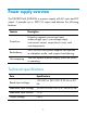
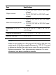
Power supply overview The PSR1800-56A (JG840A) is a power supply with AC input and DC output. It provides up to 1800 W output and delivers the following features: Feature Description Protection Protection against over-current input, under-voltage input, over-voltage output, over-current output, output short circuit, and over-temperature. Redundancy The PSR1800-56A power supplies can operate in redundant mode, and support load sharing.
Item Output current Maximum output power Specifications • 32.2 A (201 VAC to 240 VAC input voltage) • 19.6 A (100 VAC to 200 VAC input voltage) • 1800 W (201 VAC to 240 VAC input voltage) • 1100 W (100 VAC to 200 VAC input voltage) Dimensions (H × W × D) 40.1 × 82.6 × 297.7 mm (1.58 × 3.25 × 11.
Appearance Figure 1 PSR1800-56A (1) Input status LED (AC OK) (2) AC input socket (3) Latch (4) Handle (The handle is in red, indicating that the air ventilation is performed by exhausting air from the inside to the outside.) (5) Output status LED (DC OK) LEDs A PSR1800-56A has two status LEDs on its front panel. The following table lists the LED status and description.
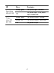
LED Input status LED (AC OK) Output status LED (DC OK) Status Description Steady green The power input is normal. Off No power input or the power input is abnormal. Steady green The power output is normal. Steady red The power output is abnormal. Off No power output.
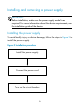
Installing and removing a power supply Safety precautions To avoid possible bodily injury and power supply and device damage, follow these safety precautions: • When you install and remove a power supply, always wear an ESD wrist strap and make sure it makes good skin contact and is well grounded.
Installing and removing a power supply IMPORTANT: Before installation, make sure the power supply model is as required. For more information about the device requirements, see the installation guide of the device. Installing the power supply To avoid bodily injury or device damage, follow the steps in Figure 2 to install the power supply.
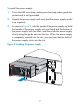
To install the power supply: 1. Put on the ESD wrist strap, making sure the strap makes good skin contact and is well grounded. 2. Unpack the power supply and verify that the power supply model is as required. 3. As shown in Figure 3, with the upside of the power supply up, hold the handle of the power supply with one hand and the bottom of the power supply with the other, and then slide the power supply slowly along the guide rails into the slot.
Figure 4 Appearance of the power supply after installation IMPORTANT: • To avoid damaging or bending the terminals of the power supply, if the insertion direction is incorrect during the installation, you must pull the power supply out, adjust the direction, and insert it again. • To remove the filler panel (if any) from the power supply slot on the device, insert a flat-blade screwdriver through the handle and pull the filler panel outward along the guide rails, as shown in Figure 5.
Figure 5 Removing the filler panel Connecting the AC power cord CAUTION: • The PSR1800-56A power supply must use the high-temperature resistant C15 connector power cord delivered with the power supply. • Turn off the circuit breaker before connecting the power cord.
To connect the power cord: 1. As shown in Figure 6, plug the female connector end of the AC power cord into the AC input socket on the switch. Figure 6 Connecting the AC power cord 2. As shown in Figure 7, use a cable tie to secure the power cord to the handle of the power supply.
3. Plug the other end of the AC power cord into the socket strip of the power source, and turn on the circuit breaker of the power source. 4. Examine the LED on the power supply. If the input status LED (AC OK) is steady green, the power cord is successfully connected. If the LED is off, examine the installation conditions, troubleshoot the problems, and try again until the LED is normal.
To remove the power supply: 1. Turn off the circuit breaker of the power cord. 2. Put on the ESD wrist strap, making sure the strap makes good skin contact and is well grounded. 3. Loosen the cable tie, and remove the power cord. 4. As shown in Figure 9, press the latch towards the handle, and pull the power supply along the guide rails until it is part-way out. 5.
6. Put the removed power supply on an antistatic mat or into its package. NOTE: If you do not insert another power supply into the slot after removing the power supply, install the filler panel to the power supply slot to prevent dust from entering the chassis.
Support and other resources Contacting HP For worldwide technical support information, see the HP support website: http://www.hp.
Related information Documents To find related documents, browse to the Manuals page of the HP Business Support Center website: http://www.hp.com/support/manuals • For related documentation, navigate to the Networking section, and select a networking category. • For a complete list of acronyms and their definitions, see HP FlexNetwork Technology Acronyms. Websites • HP.com http://www.hp.com • HP Networking http://www.hp.com/go/networking • HP manuals http://www.hp.
Command conventions Convention Description Boldface Bold text represents commands and keywords that you enter literally as shown. Italic Italic text represents arguments that you replace with actual values. [] Square brackets enclose syntax choices (keywords or arguments) that are optional. { x | y | ... } Braces enclose a set of required syntax choices separated by vertical bars, from which you select one. [ x | y | ...
GUI conventions Convention Description Boldface Window names, button names, field names, and menu items are in bold text. For example, the New User window appears; click OK. > Multi-level menus are separated by angle brackets. For example, File > Create > Folder. Symbols Convention Description WARNING An alert that calls attention to important information that if not understood or followed can result in personal injury.
Network topology icons Represents a generic network device, such as a router, switch, or firewall. Represents a routing-capable device, such as a router or Layer 3 switch. Represents a generic switch, such as a Layer 2 or Layer 3 switch, or a router that supports Layer 2 forwarding and other Layer 2 features. Represents an access controller, a unified wired-WLAN module, or the switching engine on a unified wired-WLAN switch. Represents an access point.